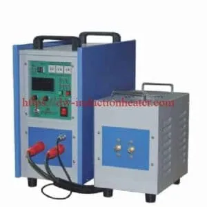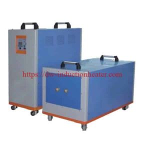
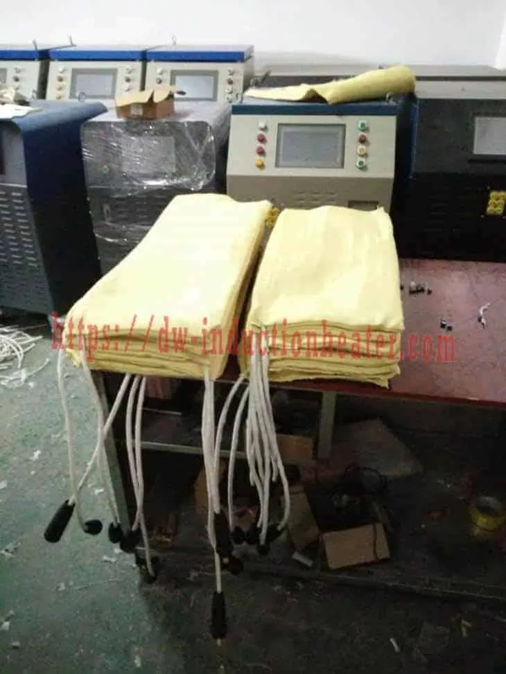
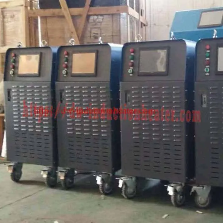




IGBT PWHT machine with DSP and PLC control
IGBT PWHT Machine with DSP and PLC Control – MYD Series, 40 to 120 kW
Quick Answer
An IGBT PWHT machine with DSP and PLC control is an induction post‑weld heat treatment power unit built in three layers. The IGBT full‑bridge inverter turns 3‑phase power into 2–30 kHz coil current. The DSP is the fast inner loop: it generates the PWM gate signals, tracks the tank’s resonant frequency and regulates output power in electrical time. The PLC with a 10‑inch touchscreen is the slow outer loop: it runs the ramp–soak–cool program on up to six K‑type thermocouples at ±3 °C, shows the alarms and stores every heating curve. A fourth layer, the ER‑1006 recorder, keeps an independent log for the quality file.
The MYD series covers 40 kW to 120 kW with input currents of 60 A to 180 A on 3‑phase 380 V (3 × 220 V and 3 × 440 V optional), an oscillation band of 2–30 kHz with automatic resonant tracking, air cooling, a heating rate capability of 5–400 °C per minute, a maximum temperature of 900 °C, 10‑curve storage with USB export, and remote operation. The MYDS series is the simplified version for preheat only, and it is not suitable for PWHT.
Two things worth knowing before you compare specification sheets across the MYD pages. The published figures for this series are not identical everywhere: the frequency band appears as 2–30 kHz in the catalogue and the model table and as 2–40 kHz on the flexible cable coil page, and the maximum temperature appears as 900 °C in the catalogue and as 0–1100 °C on that same page. And the ±3 °C figure is the control tolerance; the K‑type thermocouple itself contributes ±2.0 to ±3.3 °C on the ER‑1006, excluding cold junction error. Confirm both with HLQ for the machine being quoted.
Table of Contents
- What is the IGBT PWHT Machine with DSP and PLC Control?
- Key Applications
- Suitable Materials
- Working Principle
- Technical Specifications
- Recommended Model Selection
- Process Workflow
- Common Problems and Solutions
- Engineering Selection Guide
- Advantages and Limitations
- Why Choose HLQ?
- 6 Core FAQs
What is the IGBT PWHT Machine with DSP and PLC Control?
Post weld heat treatment only works if the steel follows the qualified thermal cycle: a limited heating rate, a soak inside a defined window, and controlled cooling, all of it recorded. At the same time, the electrical load on the coil changes as the steel heats and loses its magnetism at the Curie point. The MYD machine handles both problems with a layered control system — an IGBT power stage, a fast DSP inner loop and a PLC outer loop that follows the procedure.
| Layer | Hardware | Function | Response |
|---|---|---|---|
| Power | Rectifier + IGBT full-bridge inverter + resonant tank | Converts 3-phase 380 V into 2–30 kHz coil current | Switching at kHz rates |
| Inner loop | DSP (digital signal processor) | PWM gate drive, resonant-frequency tracking, power regulation, fault detection | Electrical (fast) |
| Outer loop | PLC + 10-inch touch screen | Ramp–soak–cool program, 6-channel temperature control, alarms, curve storage, USB, remote control | Thermal (seconds) |
| Record | ER-1006 recorder | Independent log of every channel for the QA file | Continuous |
For the complete package of coils, blankets, thermocouples and recorder, see the induction PWHT system and kit. For PWHT fundamentals and the code soak ranges, see the induction post weld heat treatment machine.

Key Applications
The five published duties differ only in which of the two control levels carries the difficulty. The DSP carries it when the load is changing underneath the coil; the PLC carries it when the soak window is narrow.
| Application | Typical job | Why the control system matters |
|---|---|---|
| Cr-Mo PWHT (P91 / P92) | Boiler headers, main steam lines | Narrow soak windows: ±3 °C keeps the soak well inside the limits |
| Pipeline girth welds | Oil and gas, district heating | Repeatable programs and a recorded chart for every joint |
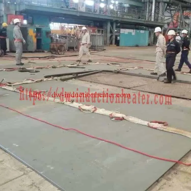
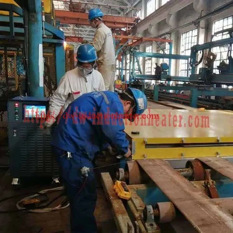
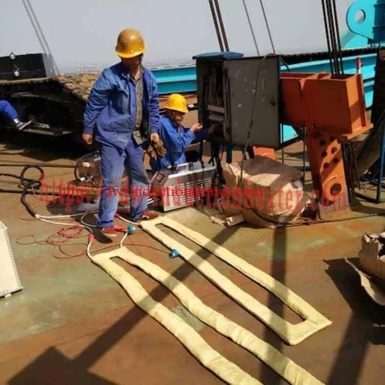
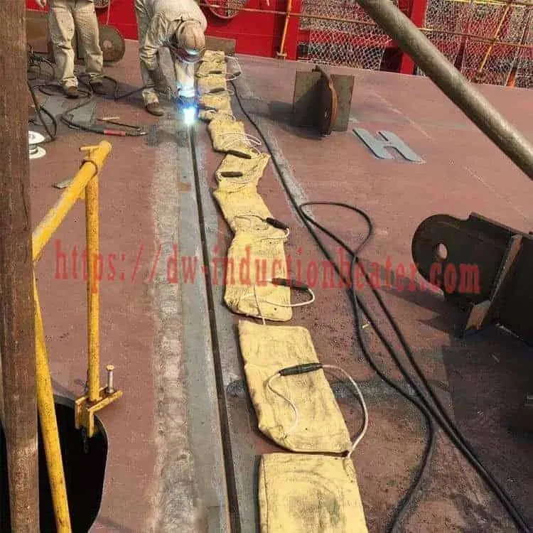
| Shipyard plate seams | Hull blocks, thick deck plates | The DSP keeps power stable as cable layouts and plate temperatures change |
| Pressure vessels and nozzles | Shells, flanges, nozzle welds | Multi-channel control around complex geometry |
| Welding preheat and interpass hold | Thick plates and pipes during welding | Closed-loop holding over long welding times |

Pipeline-specific requirements are covered in induction PWHT for oil and gas pipelines, and the girth-weld geometry and the measured field data are on the PWHT welding oil pipeline page. The tube and pipe machine itself is the tube and pipe post weld heat treatment machine.

Suitable Materials
The material sets the soak window, and the soak window sets how hard the control has to work. It also decides whether the load stays magnetic while it is being heated – and that changes how the machine behaves as the temperature climbs.
| Material | Typical PWHT soak | Magnetic at soak? | Control note |
|---|---|---|---|
| Carbon steel (P-No.1) | 595–650 °C | Yes | Wide window; standard program |
| P11 (1¼Cr-½Mo) | 650–745 °C | Yes | Recorded soak, hardness check |
| P22 (2¼Cr-1Mo) | 675–760 °C | Yes | Tighter control recommended |
| P91 / P92 (9Cr-1Mo-V) | 730–775 °C | Close to Curie | Narrow window, must stay below Ac1: ±3 °C is essential |
| Austenitic stainless steel | By specification | No | Non-magnetic load, which the DSP tracks automatically |
These are typical ranges only. The qualified PWHT procedure and the current code edition govern, and the machine has to be programmed to the procedure rather than to the table above.
One measurement note, because it is where PWHT disputes start. The published control tolerance is ±3 °C, and that is a figure about the loop. The measurement itself has its own published accuracy: the ER‑1006 recorder’s K‑type thermocouple input is ±3.3 °C from −200 to −100 °C and ±2.0 °C from −100 to 1300 °C, and the published note is explicit that this accuracy excludes cold junction error. A thermocouple that is not seated properly on clean metal, or that sits under the cable rather than beside it, adds more error than either of those numbers. That is why the joint workflow puts the thermocouples on before the coil goes on.

Working Principle

Rectifier and DC bus. 3-phase AC is rectified and filtered into a DC bus.
IGBT inverter. A full bridge of IGBTs switches the DC bus into 2–30 kHz AC, which feeds a resonant tank and the induction coil wound around the weld.
DSP inner loop. The DSP generates the PWM gate signals, measures current and voltage, keeps the inverter at the tank’s resonant frequency and regulates output power. As the steel passes the Curie point (about 770 °C), its permeability drops and the load changes; the DSP re-tracks the frequency automatically.
PLC outer loop. The PLC reads up to 6 K-type thermocouples and compares them with the programmed ramp, soak and cooling. It sends a power set point to the DSP and holds every channel within ±3 °C.
Recording. The PLC stores up to 10 heating curves for USB export, and the ER-1006 recorder keeps an independent log.
Background on eddy currents and the resonant tank is on the how an induction heater works page.

That last point deserves to be stated plainly, because it is the single most common cause of an unnecessary service call. Below the Curie point the steel is magnetic, its permeability is high, and the current is confined to a thin surface layer: 0.45 mm at 2 kHz and 0.20 mm at 10 kHz. Above the Curie point the permeability collapses, the current spreads through a much thicker layer, and the same power now moves a different amount of energy into the metal – 12.3 mm at 2 kHz and 5.5 mm at 10 kHz. The DSP re-tracks the resonant frequency automatically, so the machine copes; but the power demand falls, and a drop in output power above roughly 750 °C is normal behaviour and not a fault.
Skin depth across the MYD frequency range
| Material / condition | 2 kHz | 5 kHz | 10 kHz | 20 kHz | 30 kHz |
|---|---|---|---|---|---|
| Carbon steel below Curie (ρ 1.6×10⁻⁷ Ω·m, μr ≈ 100) | 0.45 mm | 0.28 mm | 0.20 mm | 0.14 mm | 0.12 mm |
| Stainless 304 (ρ 7.2×10⁻⁷ Ω·m, μr = 1) | 9.5 mm | 6.0 mm | 4.3 mm | 3.0 mm | 2.5 mm |
| Carbon steel above Curie (ρ 1.2×10⁻⁶ Ω·m, μr = 1) | 12.3 mm | 7.8 mm | 5.5 mm | 3.9 mm | 3.2 mm |
δ = 503 · √(ρ / (μr · f)). Below the Curie point, heat is generated in a thin surface layer and conducts through the wall. This is why moderate, code-limited heating rates give even through-wall temperatures.
IGBT vs SCR vs resistance control
| Item | IGBT inverter (MYD) | SCR / thyristor inverter | Resistance controller (pads) |
|---|---|---|---|
| Heat source | Induction in the steel | Induction in the steel | Conducted from hot ceramic pads |
| Frequency range | 2–30 kHz | Lower, less flexible | — |
| Power-stage response | Fast, digital (DSP) | Slower | On/off or phase-angle |
| Cabinet size | Compact, on wheels | Larger | Large multi-way console |
| Thermal-cycle control | PLC program, ±3 °C, 6 channels | Varies by design | Programmer per zone |
| Energy | Typically 30–80 % less than pads | Similar to IGBT | Baseline |
DSP and PLC task split
| Task | DSP | PLC |
|---|---|---|
| IGBT gate signals (PWM) | Yes | — |
| Resonant-frequency tracking | Yes | — |
| Output-power regulation | Yes (to set point) | Sets the power demand |
| Thermocouple reading and ±3 °C control | — | Yes, 6 channels |
| Ramp–soak–cool program | — | Yes |
| Alarms and error display | Fault detection | On-screen error box |
| Curve storage, USB, remote control | — | Yes (MYD) |
Technical Specifications
| Model | MYD-40 | MYD-50 | MYD-60 | MYD-80 | MYD-100 | MYD-120 |
|---|---|---|---|---|---|---|
| Output power | 40 kW | 50 kW | 60 kW | 80 kW | 100 kW | 120 kW |
| Input current (3 × 380 V) | 60 A | 75 A | 90 A | 120 A | 150 A | 180 A |
| Power device | IGBT full-bridge inverter | |||||
| Control | DSP inner loop + PLC with 10-inch touch screen | |||||
| Input power | 3 × 380 VAC (standard) · 3 × 220 VAC / 3 × 440 VAC (optional) | |||||
| Output frequency | 2–30 kHz with automatic resonant tracking | |||||
| Temperature control | Up to 6 K-type thermocouple channels, ±3 °C | |||||
| Programs and records | Ramp–soak–cool programs; 10-curve storage; USB export; ER-1006 recorder (printer optional) | |||||
| Remote operation | Supported (MYD series) | |||||
| Heating-rate capability | 5–400 °C/min (programmed to code limits for PWHT) | |||||
| Maximum temperature | 900 °C | |||||
| Protection | Fault alarm with on-screen error; automatic protection on power failure | |||||
| Cabinet / packing size | 800 × 560 × 1350 mm / 900 × 660 × 1560 mm | |||||
On the electrical figures: at 380 V the published input currents correspond to 39.4 kVA at 60 A, 49.3 kVA at 75 A, 59.2 kVA at 90 A, 78.9 kVA at 120 A, 98.6 kVA at 150 A and 118.4 kVA at 180 A. The published output powers sit just above those figures, which is consistent with a real power factor slightly under one rather than with the machine running at unity. Size the supply and the generator on the kVA, not on the output kW.

Published thermocouple accuracy of the ER-1006 recorder
| Thermocouple type | Range (°C) | Accuracy (°C) |
|---|---|---|
| B | 600–1800 | ±2.4 |
| E | −200–1000 | ±2.4 |
| J | −200–1200 | ±2.4 |
| K | −200 to −100 | ±3.3 |
| K | −100–1300 | ±2.0 |
| S | −50–100 / 100–300 / 300–1600 | ±3.7 / ±2.0 / ±1.5 |
| T | −200 to −100 / −100–380 | ±1.9 / ±1.6 |
| N | −200–1300 | ±3.0 |
| R | −50–100 / 100–300 / 300–1600 | ±3.7 / ±2.0 / ±1.5 |
| W-Re5-26 | 0–2300 | ±4.6 |
| W-Re3-25 | 0–2300 | ±4.6 |
The published note on the ER-1006 is that the accuracy excludes cold junction error. The recorder’s full specification, including the DC voltage and current inputs and the analog output, is on the PWHT chart recorder page.
MYD vs MYDS control features
| Feature | MYD (PWHT) | MYDS (preheat) |
|---|---|---|
| Touch screen | 10 in | 4.3 in |
| DSP control | Yes | Yes |
| Heating-curve storage | Yes | No |
| USB export | Yes | No |
| Recorder connector | Yes | No |
| Remote control | Yes | No |
| Maximum temperature | 900 °C | 600 °C |
| Suitable for PWHT | Yes | No |
Two points on the cooling that are published in the MYD comparison table and are worth stating here. The published entry reads “Air cooling, Water ≧100 kW”, so the MYD-100KW and MYD-120KW carry water cooling and the smaller models are air cooled – which means a cooling-water supply is needed for the two largest machines. And the MYDS series is marked as unsuitable for PWHT, so the two ranges are not interchangeable.
Standard kit for one MYD unit
| Item | Purpose |
|---|---|
| MYD power unit | IGBT power + DSP/PLC control |
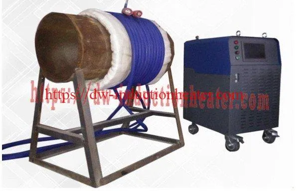
| Flexible cable induction coil | Wound around the pipe or laid on the plate seam |
| Ceramic-fibre insulation blanket | Reduces losses and evens out temperature |
| K-type thermocouples + compensating cables | Up to 6 control or monitoring points |
| Thermocouple attachment unit | Fixes thermocouples onto the steel |
| ER-1006 recorder / printer | Independent PWHT record |
The blanket and the recorder are separate published accessories: the PWHT insulation blanket and the PWHT chart recorder pages carry their own specifications.
Recommended Model Selection
| Requirement | Recommended | Reason |
|---|---|---|
| PWHT with recorded charts, pipe up to Ø610 × 50 mm | MYD-40 | Full control and recording; enough power for single joints |
| Pipe Ø610–Ø1219 or plate seams up to 3 m | MYD-60 / MYD-80 | Power margin for losses and wider heated bands |
| Long seams, vessels, heavy sections | MYD-100 / MYD-120 | High output on the same control platform |
| Preheat only, no records required | MYDS series | Simpler controller, up to 600 °C |
The rule behind the table is that the model follows the joint, not the other way round. If the joint needs a recorded chart and a narrow soak window, it needs the MYD, not the MYDS – and the MYDS is explicitly unsuitable for PWHT.
Control requirement checklist
| If your procedure requires… | Choose |
|---|---|
| Programmed heating and cooling rates | MYD (PLC programs) |
| A chart for every joint | MYD with curve storage / ER-1006, printer optional |
| More than one control point | MYD, up to 6 channels |
| Data transfer to the QA office | MYD, USB export |
| Operation from a distance | MYD, remote control |
For the coil that drives these machines, the published selection is the soft cable, the clamp coil or the water-cooled cable; see the PWHT flexible cable coil and the flexible cable coils for PWHT pages for the coil geometry, the coupling rule and the cable lengths.

Process Workflow

| Step | Operator action | What the control system does |
|---|---|---|
| 1 | Clean the joint and attach the thermocouples at the procedure positions | Displays each channel’s live reading |
| 2 | Wrap the insulation and wind the cable coil | — |
| 3 | Connect the supply, coil and thermocouple cables | Self-check; alarms on a missing phase or open thermocouple |
| 4 | Enter or recall the PWHT program on the touch screen | Stores the ramp, soak temperature and time, and cooling rate |
| 5 | Start the cycle | The DSP locks onto the resonant frequency; the PLC limits the heating rate |
| 6 | Monitor the soak | All channels held within ±3 °C; the DSP re-tracks through the Curie point |
| 7 | Controlled cooling | Power reduced along the programmed cooling rate |
| 8 | Close out | Curve stored; export by USB or print from the recorder |
Notice the order of steps 1 and 2. The thermocouples go on before the coil goes on, because once the cable is over the joint there is no access to the steel – and a thermocouple that cannot be seated properly on clean metal is worth more than any improvement in the controller.
Common Problems and Solutions
| Problem | Likely cause | Solution |
|---|---|---|
| Output power drops above ≈ 750 °C | Steel passes the Curie point, so the load changes | Normal: the DSP re-tracks. If power falls too far, check the coil turns and spacing |
| Channels oscillate around the set point | Thermocouple loose or placed under the cable | Re-attach the thermocouple on clean metal, outside the conductor path |
| One channel lags behind the others | Uneven coil spacing or insulation gap | Even out the coil turns; close the insulation gaps |
| Fault alarm at start-up | Coil not connected, phase missing, or wrong load | Check the couplings and supply phases; read the on-screen error box |
| Heating rate exceeds the code limit | Program ramp not set; machine capability is up to 400 °C/min | Enter the procedure rate in the program |
| Missing curve in the export | Recording not started or memory full | Start recording before heating; export and clear stored curves |
| Process interrupted by a power cut | Site supply failure | The machine protects itself; resume according to the procedure’s interruption rules |
Six of these seven are set-up issues rather than machine faults, and every one of them is caught by the first two steps of the workflow. The seventh – the power drop at the Curie point – is not a fault at all and should never be booked as one.

Where the machine is needed on a site without a bench supply, the same control platform is available in a portable air-cooled form; see the portable welding heater by induction page for the field unit and its heat-load sizing method.
Engineering Selection Guide

| Factor | Question to answer | Guideline |
|---|---|---|
| Soak window | How narrow is the permitted soak range? | Narrow windows (P91) need ±3 °C closed-loop control and full recording |
| Records | Is a chart required for each joint? | MYD with curve storage, USB and recorder |
| Control points | How many thermocouples? | Up to 6 per unit |
| Power | Steel mass, band width and losses? | Size from the heat load, then add the margin in the requirement table |
| Coil type | Cable, clamp or water-cooled? | See the flexible cable coils for PWHT |
| Site supply | Grid or generator? | 60–180 A at 380 V; generator ≥ 1.3 × input kVA |
| Cooling | Is there a cooling-water supply on site? | Air cooled on the MYD-40 to MYD-80; the MYD-100 and MYD-120 carry water cooling |
On the power question, the heat load is straightforward to calculate and worth doing rather than guessing. For a cylindrical band, the heated mass is m = ρ × π × (D·t − t²) × L, the energy is Q = m × cp × ΔT, and the power is P = Q / (η × τ), with η the coupling efficiency and τ the heating time. Substituting the published worked example – a 508 mm OD band with a 12.7 mm wall over a 300 mm heated length, taken from 25 °C to 230 °C, with ρ = 7850 kg/m³, cp = 0.490 kJ/kg·K and η = 70 % – gives a mass of 46.54 kg, 4,675 kJ of energy and, for a 90 second cycle, 74.2 kW, or 89.0 kW with a 20 % margin, which lands on the MYD-100KW. The full method, with all six candidate heating times worked through, is on the portable welding heater page.
Heating and cooling rate limits (ASME VIII UCS-56, carbon steel)
| Wall thickness | Max heating rate above 427 °C | Max cooling rate above 427 °C |
|---|---|---|
| 25 mm | 222 °C/h | 278 °C/h |
| 50 mm | 111 °C/h | 139 °C/h |
| 75 mm | 74 °C/h | 93 °C/h |
| 100 mm and above | 56 °C/h (minimum limit) | 69 °C/h |
Rates are 222 × 25 / t and 278 × 25 / t (°C/h, t in mm), with a lowest required limit of 56 °C/h. Always check the current edition of the governing code. For soak times and carbon-steel cycle rules, see induction stress relief heat treatment.
Advantages and Limitations
| Advantages | Limitations |
|---|---|
| Fast digital power control (DSP) with automatic frequency tracking | Electronics need a clean, adequately sized 3-phase supply |
| Programmed cycles with ±3 °C on 6 channels | Operators need training in programming and thermocouple placement |
| Curve storage, USB export, remote control | The MYDS series lacks the recording functions |
| Compact IGBT cabinet on wheels | Published net weight 120 kg, gross weight with parts 155–260 kg |
| Typically 30–80 % energy saving versus resistance pads | Higher upfront cost than pad systems |
| Automatic re-tracking through the Curie point, so no operator action is needed when the load changes | The MYD-100 and MYD-120 carry water cooling and need a cooling-water supply on site |
Why Choose HLQ?
| Strength | What it means for you |
|---|---|
| Layered IGBT + DSP + PLC control | Stable power and accurate, programmed thermal cycles |
| Records built in | 10-curve storage, USB export and an independent recorder |
| Two control levels | MYD for PWHT, MYDS for economical preheat |
| Matched kits | Coils, blankets and thermocouples sized for your joints |
| Field-proven | Pipelines, shipyards and fabrication shops |
HLQ Induction Equipment is a direct manufacturer in Quanzhou, Fujian, with 25 years of experience in the research and development, design and production of high-frequency and medium-frequency induction heating machines. IGBT medium-frequency induction heating equipment and medium-frequency induction melting furnaces are leading products in that range, together with open-type and closed water cooling towers – so the power supply, the coil and the cooling system on a station come from the same organisation.
The machine is test-run and debugged by HLQ’s own technical staff before shipment, with a dedicated QC person inspecting production and a QC team working to TQM; photographs and video of the build are available on request. Engineers are sent to the customer’s workshop for installation, commissioning and training until the machine is running normal production. Packing is a film layer, a paper box, a wooden exporting case and foam for shockproof, shipping is free to the buyer’s shipper in China or direct to any main port of China, and the heating power carries a warranty of 12 months from the date the contract was signed.
6 Core FAQs
1. What does the DSP do that the PLC cannot?
The DSP is the electrical half of the machine and the PLC is the thermal half. The DSP generates the PWM gate signals for the IGBTs, measures current and voltage, holds the inverter at the tank’s resonant frequency and regulates output power – all of it fast enough to act within a switching cycle. The PLC runs the ramp–soak–cool program, reads up to six thermocouples and sends the DSP a power set point. The split exists because the two tasks have completely different time scales: the electrical loop reacts in milliseconds, the thermal loop in seconds.
2. Why does the output power drop above about 750 °C, and is it a fault?
It is normal. At the Curie point, around 770 °C, the steel loses its magnetism and its permeability collapses, so the skin depth and the load the coil sees both change: on carbon steel at 2 kHz the skin depth goes from 0.45 mm below the Curie point to 12.3 mm above it, and at 10 kHz from 0.20 mm to 5.5 mm. The same power now moves a different amount of energy into the metal, so the power demand falls. The DSP re-tracks the resonant frequency automatically and the machine copes without operator action. Only if the power falls further than the change explains should you check the coil turns and spacing.
3. How accurate is the temperature control, really?
Two separate numbers, and it is worth keeping them apart. The published control tolerance is ±3 °C on up to six K-type thermocouple channels, and that is a figure about the loop – how tightly the PLC holds the channels together and on the programmed ramp. The measurement underneath has its own published accuracy: on the ER-1006 recorder, a K-type thermocouple is ±3.3 °C from −200 to −100 °C and ±2.0 °C from −100 to 1300 °C, and the published note is explicit that this excludes cold junction error. A thermocouple that is not seated on clean metal, or that sits under the cable rather than beside it, contributes more error than either figure – which is why the workflow puts the thermocouples on before the coil goes on.
4. Can the machine heat faster than the code allows?
The machine can; the program must not. The published heating-rate capability is 5–400 °C per minute, while ASME VIII UCS-56 limits the heating rate above 427 °C to 222 °C/h for a 25 mm wall, falling to 56 °C/h for 100 mm and above, with cooling limits of 278 °C/h and 69 °C/h. So the ramp and the cooling rate have to be entered from the procedure rather than left at the machine’s capability, and on a P91/P92 job the soak window is narrow enough that ±3 °C is essential.
5. What is the difference between MYD and MYDS, and which one do I need?
MYDS is the simplified controller for preheat only: a 4.3-inch screen, no heating-curve storage, no USB export, no recorder connector, no remote control, and a maximum temperature of 600 °C against MYD’s 900 °C. The published comparison marks MYDS as unsuitable for PWHT. So if the job involves a qualified post-weld heat treatment with a soak window and a recorded chart per joint, it needs the MYD; MYDS is for preheat and interpass hold where no records are required.
6. Can the heating records be exported and used for the QA file?
Yes. The MYD stores up to 10 heating curves for USB export, and the ER-1006 recorder keeps an independent continuous log of every channel, with a printer optional. On a PWHT job that record is normally what the client, the inspector or the code asks for – it is the only evidence that the joint reached the required temperature for the required time without overheating the parent metal. The recorder’s own input accuracy for a K-type thermocouple is published as ±2.0 °C over the working range, excluding cold junction error, and the full specification is on the PWHT chart recorder page.