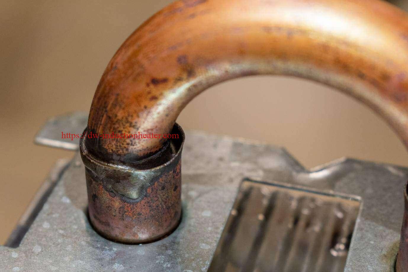
Optimizing HVAC Brazing with Induction Heating
Quick answer: Induction heating improves HVAC brazing by putting heat only where the joint needs it, in a cycle that can be repeated part after part. Copper-to-copper and copper-to-brass tube joints on coils, compressors, valves and line sets can be brazed in seconds without an open flame. Compared with a torch, induction reduces oxidation, rework and leak failures, and it moves easily from a handheld tool to a fully automated line.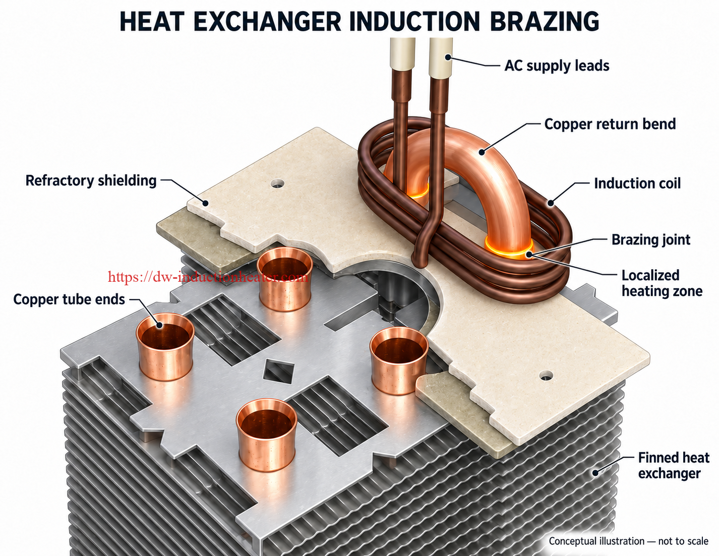
Contents
- Why HVAC brazing needs optimizing
- How induction brazing works
- Typical HVAC joints
- Filler metals and flux
- Coil design
- Optimized process workflow
- Key process parameters
- Common problems and fixes
- From handheld to automated lines
- Induction vs torch brazing
- FAQ
Why HVAC Brazing Needs Optimizing
A single air conditioner or heat pump can contain dozens of brazed joints, and every one must stay leak-tight under refrigerant pressure and years of thermal cycling. Torch brazing relies on the skill of each operator, so heat input varies from joint to joint. That variation causes:
- cold joints where the filler never fully flows
- overheated joints with excess oxide, eroded walls or burnt flux
- distortion of thin tubes and heat damage to nearby parts
- slow cycles and rework found only at leak testing
Induction addresses each of these by controlling heat location, power and time electronically.
How Induction Brazing Works
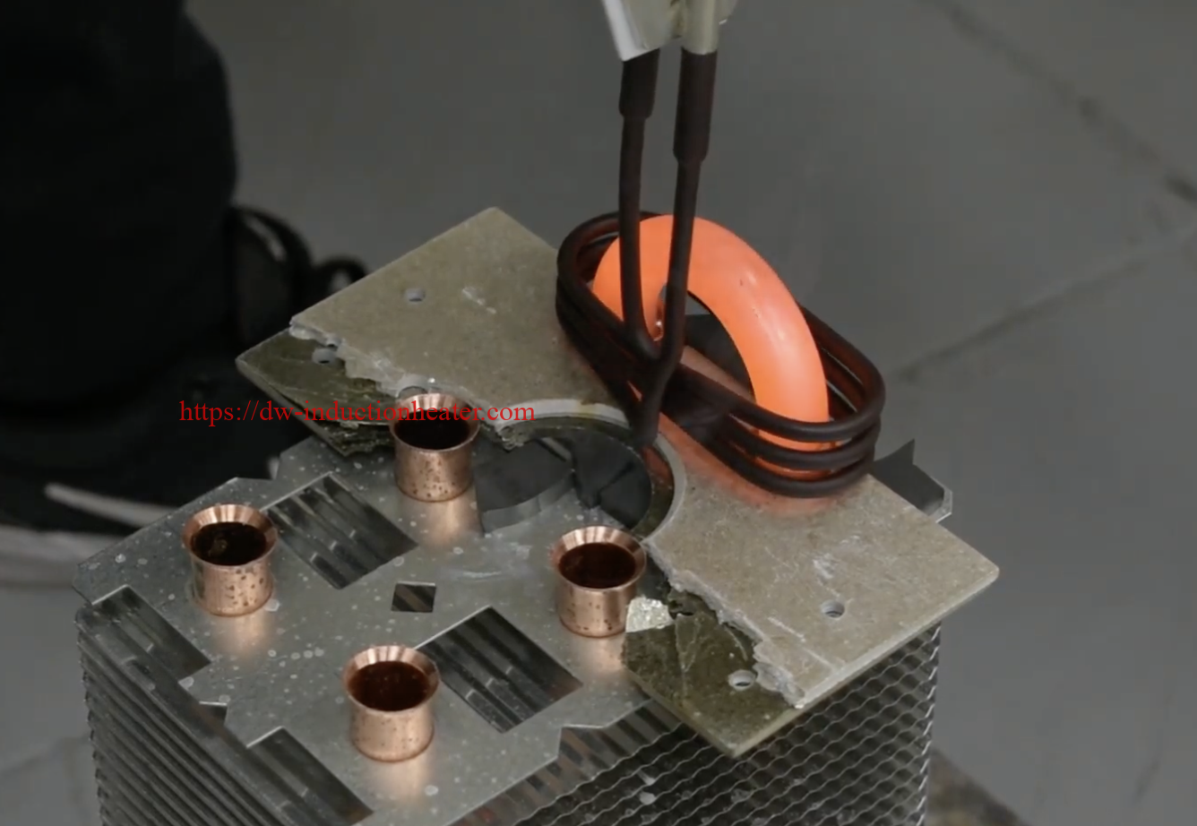
An induction power supply drives a high-frequency alternating current through a water-cooled copper coil placed around or beside the joint. The coil’s magnetic field induces eddy currents in the tube and fitting, and the metal’s own electrical resistance turns those currents into heat. The coil itself stays cool.
When the joint reaches the filler’s flow temperature, a preformed ring or wire melts, and capillary action draws it into the clearance between tube and fitting. Heating stops as soon as a continuous fillet forms, and the joint solidifies within seconds.
Copper has very low electrical resistance and very high thermal conductivity. As a result, HVAC joints need close coil coupling, enough power to beat heat loss along the tube, and short, concentrated cycles.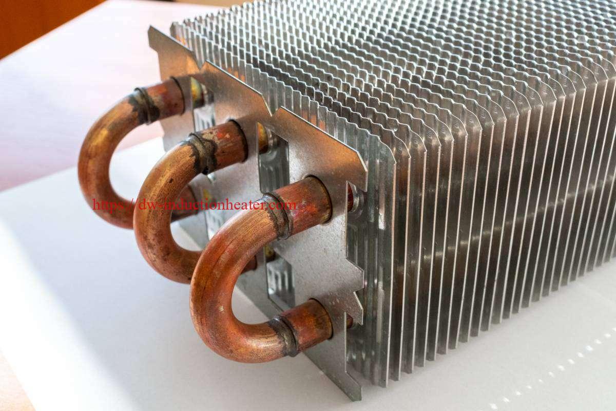
Typical HVAC Joints
| Joint | Where it is found | Main challenge |
|---|---|---|
| Copper return bends to coil tubes | Evaporator and condenser coils | Many closely spaced joints; access for the coil |
| Copper tube to copper fitting | Line sets, headers, distributors | Even heating around the full circumference |
| Copper tube to brass valve or fitting | Service valves, filter driers, connectors | Brass overheats and loses zinc if heated too long |
| Copper tube to steel shell | Compressor suction and discharge stubs, accumulators | Steel and copper heat at very different rates |
| Capillary tube joints | Expansion devices, distributors | Very small mass; easily melted or blocked |
Filler Metals and Flux
| Filler family | Typical use | Flux needed? |
|---|---|---|
| Copper-phosphorus (Cu-P) | Copper to copper | No: self-fluxing on copper |
| Copper-phosphorus-silver (Cu-P-Ag) | Copper to copper where more ductility is needed | No on copper; yes on brass |
| Silver brazing alloys | Copper to brass, copper to steel | Yes: paste flux on both surfaces |
Phosphorus-bearing fillers must not be used on steel, because they form brittle phosphides. Preformed rings give the same amount of alloy in every joint, which is the single biggest step toward repeatable results.
Coil Design
- Closed helical coils heat most evenly. Use them where the tube can be passed through the coil.
- Open (C-type) coils slide onto a joint from the side. Use them for joints already in place on coils and assemblies.
- Channel coils let parts drop in from above, for fast loading in production.
- Multi-joint coils heat two or more neighbouring joints at the same time, for example paired return bends.
- Field concentrators made of magnetic flux-guide material focus energy on the joint and shield nearby parts.
On copper-to-brass and copper-to-steel joints, bias the coil toward the copper side, because the other metal heats faster.
Optimized Process Workflow
- Prepare: cut tubes square, deburr, and clean off oil and oxide.
- Check fit-up: a small, even clearance is what makes capillary flow work.
- Apply filler: seat a preformed ring at the joint mouth and add flux where the filler needs it.
- Position: use a fixture or locating guide so the coil sits in the same place every time.
- Heat: run a set power and time, or ramp the power for dissimilar joints.
- Confirm flow: look for a continuous fillet all the way round, then stop heating.
- Cool: leave the joint undisturbed until the filler solidifies.
- Clean and test: remove flux residue, inspect visually, and pressure or helium leak test.
Key Process Parameters
| Parameter | Typical range for HVAC copper joints | Effect |
|---|---|---|
| Brazing temperature | Roughly 700–850 °C, set by the filler | Too low: incomplete flow. Too high: erosion and oxide. |
| Frequency | Tens to a few hundred kHz | Higher frequency concentrates heat at the surface of small tubes. |
| Power | A few kW for small tubes; tens of kW for large lines | Must outpace heat conducted away along the copper. |
| Cycle time | Seconds for small joints; under a minute for large ones | Shorter cycles mean less oxidation and less heat spread. |
| Joint clearance | Small and uniform | Controls capillary flow and joint strength. |
Exact settings depend on tube size, wall thickness and filler. Fix them with sample tests before production.
Common Problems and Fixes
| Problem | Likely cause | Fix |
|---|---|---|
| Filler flows on one side only | Uneven coil coupling or an open-coil gap | Centre the coil; rotate the part; pulse the power |
| Fillet incomplete | Too little time or power; dirty surfaces | Clean the parts; extend the cycle; check clearance |
| Tube wall eroded or melted | Overheating | Reduce power or time; stop at first full flow |
| Brass fitting discoloured or porous | Zinc loss from overheating | Bias the coil to the copper; shorten the cycle |
| Heavy oxide inside the tube | Long heating time in air | Shorter cycles; nitrogen purge through the tube |
| Leaks found at test | Voids from flux entrapment or poor fit | Control fit-up; use preforms; avoid excess flux |
From Handheld to Automated Lines
- Handheld systems: a light heating head on a flexible cable reaches joints on large coils or installed equipment.
- Bench stations: a fixed coil and fixture with timer control suit repeat parts.
- Automated cells: rotary tables, conveyors or robots load parts or carry the heating head, with PLC recipes and temperature monitoring for each joint.
Because the heating method stays the same, a process proven on a handheld unit can move to automation with few changes.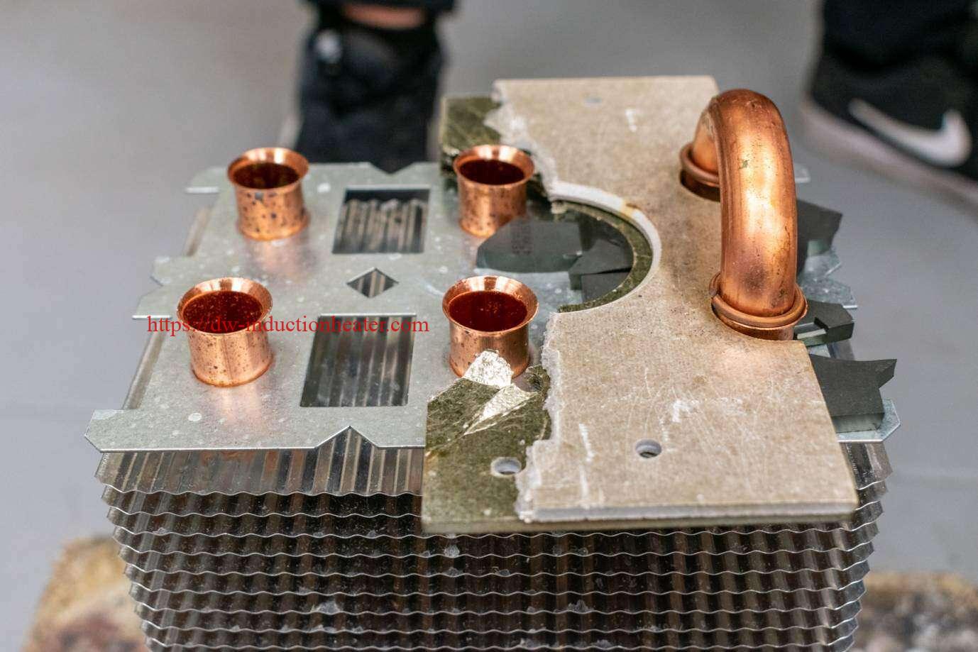
Induction vs Torch Brazing
| Factor | Torch brazing | Induction brazing |
|---|---|---|
| Heat control | Depends on operator skill | Set power and time, repeatable |
| Heated area | Wide; flame spreads heat | Localized to the joint |
| Open flame and gas | Yes | No |
| Oxidation and distortion | Higher | Lower |
| Cycle consistency | Variable | Consistent part to part |
| Automation | Difficult | Straightforward |
| Initial cost | Low | Higher, offset by speed and quality |
FAQ
Is induction brazing strong enough for refrigerant lines?
Yes. A correctly brazed joint is leak-tight and can be stronger than the tube. Consistent heat makes that quality repeatable.
Can one machine braze different tube sizes?
Yes, usually by changing the coil and adjusting power and time for each joint size.
Do I need flux for copper-to-copper joints?
Not with copper-phosphorus fillers, which self-flux on copper. Copper-to-brass and copper-to-steel joints need flux with a silver alloy.
How is joint quality checked?
Check the fillet visually, pressure or helium leak test the parts, and periodically cross-section sample joints.
Is induction brazing safer than a torch?
Yes. There is no open flame or fuel gas at the workstation, and less heat radiates around the operator.