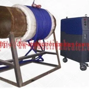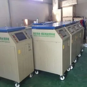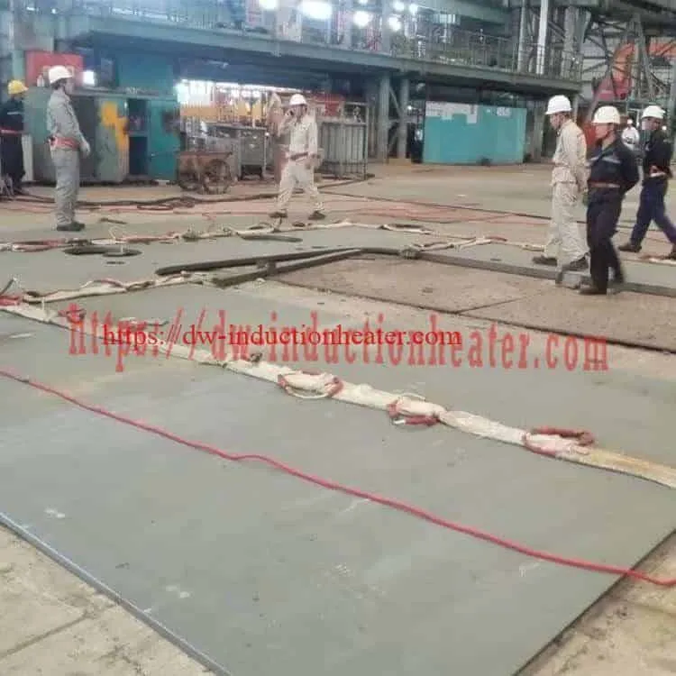
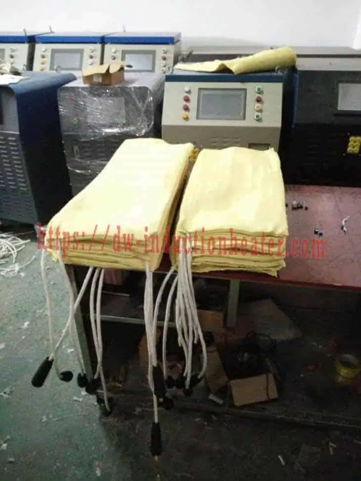

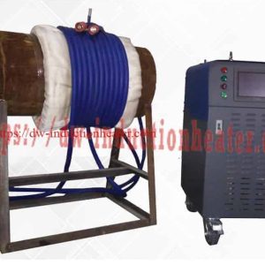


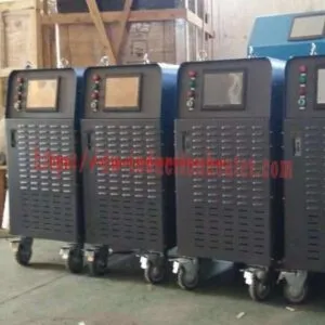

IGBT PWHT machine with DSP and PLC control
Induction PWHT Machine for Post Weld Heat Treatment & Stress Relief
Quick Answer: What Is an Induction PWHT Machine?
An induction PWHT machine is an industrial heating system designed for controlled post weld heat treatment, weld stress relieving, and preheating of welded metal components. It uses electromagnetic induction to heat the weld area and adjacent base metal through a flexible induction cable or application-specific heating coil.
The HLQ MYD series induction post weld heat treatment machines are published in six power classes: 40 kW, 50 kW, 60 kW, 80 kW, 100 kW, and 120 kW. The published operating frequency range is 2–30 kHz, with three-phase 380 V as the standard electrical supply and alternative voltage configurations listed as options.
MYD induction heating equipment combines IGBT power electronics, DSP-based control, PLC interface options, temperature monitoring, and configurable heating cables to support industrial PWHT applications.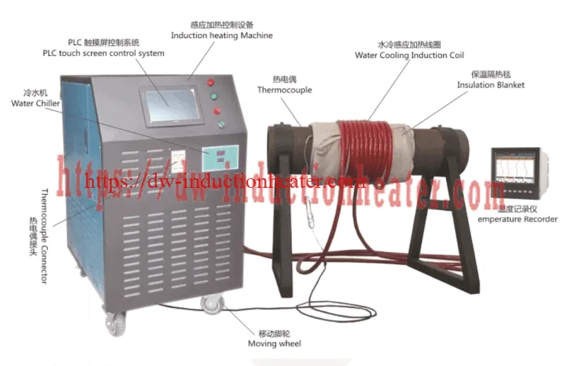
Typical applications include oil and gas pipelines, pressure vessels, boilers, steel structures, shipbuilding, petrochemical piping, and industrial welding repairs.
Important: The required PWHT temperature, heating rate, holding time, heating band width, and cooling rate must be determined by the governing fabrication code and an approved heat treatment procedure. Equipment capability alone does not establish code compliance.
Key Technical Parameters at a Glance
| Parameter | Published MYD Series Information |
|---|---|
| Equipment Type | Induction Post Weld Heat Treatment Machine |
| Product Series | HLQ MYD Series |
| Published Models | MYD-40KW, MYD-50KW, MYD-60KW, MYD-80KW, MYD-100KW, MYD-120KW |
| Nominal Power Classes | 40–120 kW |
| Operating Frequency | 2–30 kHz, published series range |
| Standard Electrical Input | 3-phase 380 V, 50/60 Hz |
| Optional Input Voltages | 3-phase 220 V / 440 V, subject to confirmation |
| Published Maximum Temperature | 900°C equipment/control limit; not a universal PWHT setpoint |
| Control System | DSP and PLC-based control configuration |
| Temperature Measurement | K-type thermocouples and temperature recording options |
| Induction Heating Coil | Flexible induction cable or customized coil |
| Typical Workpieces | Pipes, pressure vessels, boilers, tanks, welded structures and industrial components |
| Cooling Configuration | Air-cooled or water-cooled arrangements according to equipment specification |
Specification note: The table summarizes published product information. Current rated output, electrical current, cooling configuration, and control-channel capabilities should be verified against the applicable MYD model datasheet.
What Is an Induction Post Weld Heat Treatment Machine?
An induction post weld heat treatment machine is a controlled industrial heating system used to apply a specified thermal cycle to welded components after welding. Depending on the material and approved procedure, PWHT can reduce welding residual stresses, temper certain hardened microstructures, and help achieve the required mechanical properties.
During welding, localized heating and cooling create thermal gradients and residual stresses in the weld metal and heat-affected zone (HAZ). Some materials and fabrication applications require additional heat treatment after welding.
Unlike furnace heating, an induction PWHT system can heat a defined region of a large component without necessarily heating the entire structure.
This makes induction heating particularly useful for installed pipelines, pressure vessels, heavy steel structures, large tanks, and field welding repairs.

What Does PWHT Achieve?
| PWHT Objective | Engineering Explanation | Important Qualification |
|---|---|---|
| Residual Stress Reduction | Elevated temperature can promote stress relaxation in welded metal. | Residual stress is reduced, not necessarily eliminated. |
| Hardness Control | Appropriate tempering may reduce excessive hardness in susceptible steels. | The response depends on alloy, weld microstructure and temperature. |
| Microstructure Modification | Controlled heating can temper or modify certain weld and HAZ microstructures. | Incorrect cycles may degrade properties. |
| Dimensional Stability | Stress relaxation may reduce the tendency toward later distortion. | Heating itself can also cause distortion if poorly controlled. |
| Specification Compliance | Documented PWHT may be required by the governing fabrication standard. | A qualified procedure and records are essential. |
Preheating, Postheating and PWHT: What Is the Difference?
| Process | When Applied | Primary Purpose |
|---|---|---|
| Weld Preheating | Before and during welding | Control cooling rate and reduce hydrogen-cracking risk where applicable |
| Postheating / Hydrogen Bake-Out | After welding, under an approved procedure | Promote hydrogen diffusion in susceptible materials |
| Post Weld Heat Treatment | After welding | Apply a specified thermal cycle for stress relief or metallurgical requirements |
| Stress-Relief Heat Treatment | After welding or fabrication | Reduce residual stresses through controlled heating and cooling |
Although the same induction heating platform may support several of these operations, the temperature profile and acceptance requirements are different.
Key Applications of Induction PWHT Machines
MYD induction PWHT equipment can be considered for industrial applications requiring localized, controlled heat treatment of electrically conductive metal components.
1. Oil and Gas Pipeline Welding
Induction heating is used for selected pipeline welds where the applicable welding procedure requires preheating, controlled postheating, or PWHT.
Flexible induction heating cables can be arranged around the pipe circumference to provide a defined heating band around the welded joint.
Applications may include:
- Oil and gas transmission pipeline fabrication
- Refinery process piping
- Petrochemical plant piping
- Pipeline tie-in welds
- Pipeline repair and replacement sections
- Power plant piping systems
Additional application information is available in induction PWHT machines for oil and gas pipelines.
2. Pressure Vessel Weld Heat Treatment
Pressure vessels may require PWHT depending on their design code, material grade, wall thickness, welding procedure, and service conditions.
Localized induction heating can be considered for circumferential welds, selected nozzle connections, and approved repair areas.
Particular attention must be paid to heating-band dimensions, circumferential uniformity, restraint, temperature gradients, and applicable local PWHT restrictions.
3. Boiler and Power Plant Piping
Boiler systems and power generation facilities contain welded components made from carbon steel, low-alloy steel, and creep-resistant alloys.
In these applications, controlled heating and accurate temperature recording are essential because incorrect thermal treatment may affect high-temperature mechanical properties.
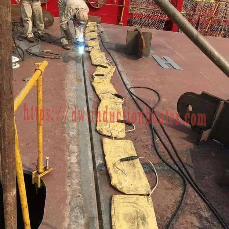
4. Shipbuilding and Offshore Structures
Shipboard construction, offshore modules, and heavy fabricated structures may require localized heat treatment under approved welding and fabrication procedures.
Induction heating can provide a practical alternative to large furnace heating when the component cannot be transported or treated as a complete assembly.
5. Steel Structures and Heavy Fabrication
Large fabricated steel components can contain substantial residual stresses after welding.
Induction heating may be used for local stress-relief procedures where permitted by the governing design code and approved fabrication specification.
More information about these applications is provided in post welding stress relieving with induction heating.
6. Maintenance and Industrial Weld Repairs
Field-deployable induction systems can support heat-treatment procedures for selected industrial repairs without requiring complete removal of large components.
The repair procedure must account for nearby insulation, coatings, electrical equipment, sensitive components, and restrictions on heating an installed system.
Application Summary
| Industry | Typical Workpiece | Primary Heating Requirement | Key Engineering Concern |
|---|---|---|---|
| Oil & Gas | Pipeline girth welds | Controlled circumferential heating | Temperature uniformity |
| Petrochemical | Process piping | Localized PWHT | Material-specific thermal cycle |
| Power Generation | Boiler and steam piping | Controlled weld heat treatment | Alloy and creep-property requirements |
| Pressure Vessel Manufacturing | Shell welds and nozzles | Approved local PWHT | Heating width and gradients |
| Shipbuilding | Heavy steel structures | Localized stress relief where permitted | Distortion and access |
| Industrial Maintenance | Repair welds | Controlled heating and recording | Field safety and code compliance |
Suitable Materials for Induction Post Weld Heat Treatment
Induction heating can transfer energy to many electrically conductive metals. However, the ability to heat a material does not automatically mean that a specific PWHT cycle is appropriate.
The material grade, heat-treatment history, welding procedure, and governing construction standard determine whether PWHT is required and how it must be performed.
Material Compatibility Table
| Material | Induction Heating Suitability | PWHT Engineering Considerations |
|---|---|---|
| Carbon Steel | Generally suitable | Confirm material specification, thickness and code requirements |
| Low-Alloy Steel | Generally suitable | Check composition, hardness and heat-treatment condition |
| ASTM A106 Steel | Suitable for induction heating | PWHT requirements depend on grade and applicable piping code |
| ASTM A335 P11 | Suitable with controlled thermal procedures | Verify temperature range and holding requirements |
| ASTM A335 P22 | Suitable with controlled thermal procedures | Review alloy-specific tempering requirements |
| ASTM A335 P91 | Technically heatable | Requires strict grade-specific procedure and metallurgical control |
| ASTM A335 P92 | Technically heatable | Requires qualified creep-resistant alloy procedure |
| Austenitic Stainless Steel | Suitable with appropriate equipment | PWHT may be inappropriate for certain grades or corrosion-service conditions |
| Duplex Stainless Steel | Requires specialist evaluation | Incorrect thermal treatment can damage phase balance and corrosion resistance |
| High-Strength Low-Alloy Steel | Generally heatable | Verify strength and toughness requirements before treatment |
Material Properties for Preliminary Heat Calculations
| Material | Approximate Density | Representative Specific Heat | Important Note |
|---|---|---|---|
| Carbon Steel | 7,850 kg/m³ | 0.46–0.65 kJ/(kg·K) | Specific heat generally varies with temperature |
| Low-Alloy Steel | 7,750–7,850 kg/m³ | Approximately 0.45–0.65 kJ/(kg·K) | Use alloy-specific data for final design |
| 304 Stainless Steel | Approximately 8,000 kg/m³ | Approximately 0.50–0.60 kJ/(kg·K) | Heating characteristics differ from carbon steel |
| 316 Stainless Steel | Approximately 8,000 kg/m³ | Approximately 0.50–0.60 kJ/(kg·K) | Confirm temperature-dependent properties |
These are representative engineering values, not certified material properties. Average specific heat over the complete heating interval is required for an accurate energy calculation.
Material Selection Checklist
- Base-metal grade and applicable material standard
- Weld filler-metal classification
- Actual material thickness
- Previous heat-treatment condition
- Governing design or fabrication code
- Approved welding procedure specification
- Required PWHT temperature and holding duration
- Permissible heating and cooling rates
- Required hardness, toughness and inspection criteria
Working Principle of an Induction PWHT Machine
The MYD induction PWHT system uses solid-state power electronics to generate alternating current at a controlled output frequency.
When current flows through the induction heating cable, it produces a changing magnetic field around the workpiece.
This magnetic field induces electrical currents in the conductive metal. The resulting resistive losses generate heat within the workpiece.
For ferromagnetic steels, magnetic properties also influence the distribution and intensity of heating.
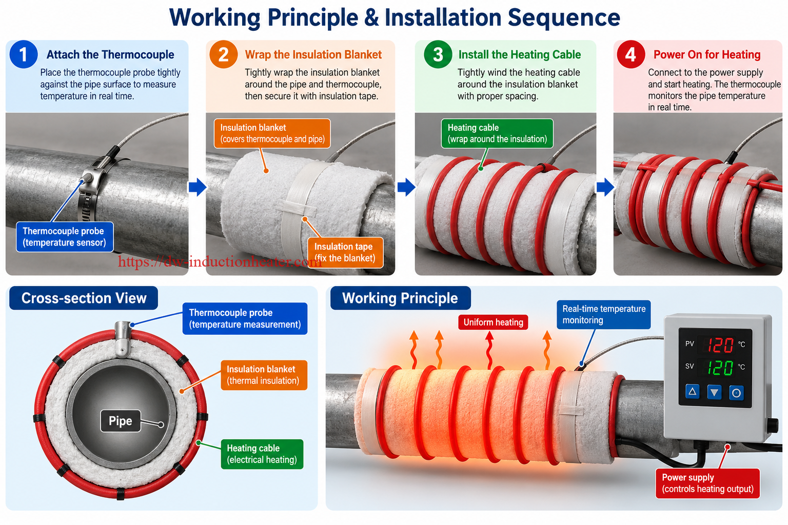
Induction PWHT Heating Sequence
- Power Conversion: The induction power supply converts incoming electrical energy into controlled medium-frequency power.
- Magnetic Field Generation: The flexible induction cable produces a changing magnetic field.
- Heat Generation: Induced electrical currents generate heat in the conductive workpiece.
- Temperature Measurement: Thermocouples measure temperatures at specified monitoring points.
- Closed-Loop Regulation: The controller adjusts heating output to follow the programmed profile.
- Temperature Recording: A suitable recorder documents the heating cycle for inspection and traceability.
System Components
| Component | Function |
|---|---|
| IGBT Induction Power Supply | Produces controlled induction heating power |
| Flexible Induction Cable | Generates the magnetic field around the workpiece |
| Connection Cable | Connects the power supply and heating arrangement |
| Thermal Insulation Blanket | Reduces heat losses and helps control temperature gradients |
| K-Type Thermocouple | Measures workpiece temperature |
| Temperature Controller | Controls the programmed thermal cycle |
| Temperature Recorder | Documents heating and cooling history |
| Cooling System | Maintains permissible operating temperatures of relevant equipment components |
Why Is a Flexible Induction Cable Used?
A flexible induction cable can be arranged around pipes, nozzles, rings, and other accessible components.
Its main advantages include adaptable coil geometry, localized heating, and suitability for large components that cannot be placed inside a conventional furnace.
The cable must be compatible with the generator, selected frequency, current, thermal insulation and installation environment.
For related equipment applications, see induction preheating and post-heating systems for welding.
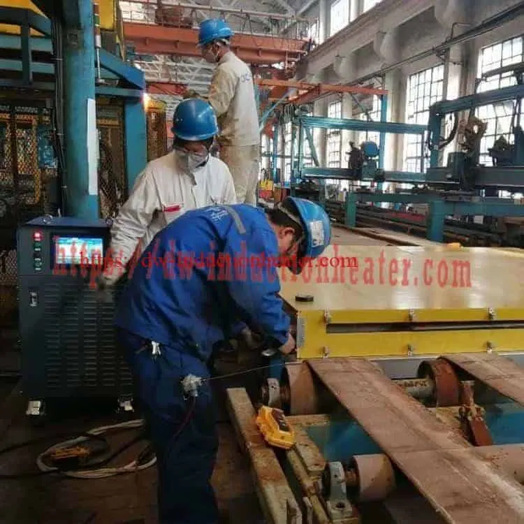
Induction Heating and Resistance Heating
| Feature | Induction Heating | Resistance Heating |
|---|---|---|
| Heat Generation | Electromagnetic heating within the conductive metal | Heat generated in electrical heating elements and transferred to the workpiece |
| Heating Arrangement | Induction cable or coil | Ceramic resistance pads or other resistance elements |
| Temperature Control | Possible with thermocouple feedback | Possible with thermocouple feedback |
| Heating Uniformity | Depends on coil design, geometry and insulation | Depends on pad arrangement, contact and insulation |
| Energy Consumption | Application-dependent | Application-dependent |
| Site Installation | Flexible for many circular and accessible workpieces | Flexible for many surface and complex heating applications |
| PWHT Compliance | Requires a qualified process and documented records | Requires a qualified process and documented records |
Neither heating method is automatically superior for every application. The most appropriate method depends on component geometry, installation access, heating width, available electrical supply, and the required thermal cycle.
Technical Specifications of MYD Induction PWHT Machines
HLQ publishes six MYD series induction PWHT power classes from 40 kW to 120 kW.
The following model table preserves the values provided on the original product page.
MYD Series Model Comparison
| Model | Published Output Rating | Published Input Current | Published Frequency Range |
|---|---|---|---|
| MYD-40KW | 40 kW | 60 A | 2–30 kHz |
| MYD-50KW | 50 kW | 75 A | 2–30 kHz |
| MYD-60KW | 60 kW | 90 A | 2–30 kHz |
| MYD-80KW | 80 kW | 120 A | 2–30 kHz |
| MYD-100KW | 100 kW | 150 A | 2–30 kHz |
| MYD-120KW | 120 kW | 180 A | 2–30 kHz |
Electrical qualification: The current figures above are transcribed from the published page and should be treated as provisional. At three-phase 380 V, actual input power depends on current, power factor and conversion efficiency. The published values require reconciliation before use in electrical installation design.
General Technical Configuration
| Technical Parameter | Published Information | Engineering Note |
|---|---|---|
| Electrical Supply | 3-phase 380 V, 50/60 Hz | Check rated input current and site capacity |
| Optional Voltage | 3-phase 220 V or 440 V | Confirm availability for the selected model |
| Output Frequency | 2–30 kHz | Actual operating frequency depends on load and configuration |
| Maximum Published Temperature | 900°C | Not a recommended universal PWHT temperature |
| Published Heating Rate | 5–400°C/min | Do not use directly as a code-compliant process setting |
| Controller | DSP / PLC configuration | Confirm exact controller specification |
| Temperature Monitoring | Six-channel capability is mentioned | Confirm whether channels are for measurement, recording or control |
| Temperature Sensor | K-type thermocouple | Confirm sensor rating and calibration requirements |
| Coil | Flexible induction cable | Length, temperature rating and cooling must match the application |
| Cooling | Air-cooled / water-cooled configurations described | Confirm power supply and coil cooling separately |
| Control Accuracy | Original page mentions ±3°C | Requires verification under defined test conditions |
| Cabinet Dimensions | 800 × 560 × 1350 mm listed | Model-specific applicability is not established |
| Published Net Weight | 120 kg listed | Not confirmed for every model |
Accessories and Optional Components
| Accessory | Published / Representative Configuration | Purpose |
|---|---|---|
| Flexible Induction Cable | 25 m option listed | Heating of weld joints and surrounding metal |
| Alternative Heating Cable | 10–45 m range also appears in source information | Selection according to workpiece and generator |
| Thermal Insulation Blanket | 1500 × 600 × 50 mm example | Heat retention and thermal gradient management |
| Alternative Insulation Blanket | 900 × 600 × 50 mm example | Localized workpiece insulation |
| K-Type Thermocouple | Workpiece temperature measurement | Temperature feedback and verification |
| Thermocouple Extension Cable | 10 m example | Connects sensors to the monitoring system |
| Connection Cable | 10 m example | Connects induction generator and heating assembly |
| Temperature Recorder | ER/R-1006 designation appears in published information | Temperature history recording |
Accessory quantities, component temperature ratings and included scope must be established for each equipment configuration.
MYD vs. MYDS Series
| Parameter | MYD Series | MYDS Series |
|---|---|---|
| General Positioning | Controlled induction heating and PWHT applications | Primarily induction preheating and general heating applications |
| Published Maximum Temperature | 900°C | 600°C |
| Controller | DSP with PLC interface | DSP with different interface configuration |
| Temperature Recording | Recorder interface and curve storage listed | Original comparison lists fewer recording functions |
| PWHT Suitability | Listed as supported | Listed as unsupported in the original comparison |
| Final Selection | Confirm complete PWHT configuration | Do not substitute without written technical validation |
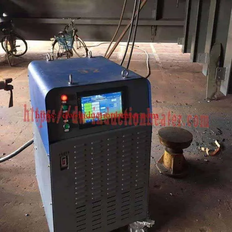
Recommended MYD Induction PWHT Machine Model Selection
Selecting an induction PWHT system requires more than choosing the rated power printed on the equipment.
Effective power transfer depends on workpiece geometry, material properties, heating cable design, thermal insulation, target temperature, temperature uniformity and required cycle time.
Preliminary Model Selection Matrix
| Model | Power Class | Potential Application | Selection Conditions |
|---|---|---|---|
| MYD-40KW | 40 kW | Localized pipe weld heating and smaller fabrication tasks | Verify workpiece mass, temperature and heating profile |
| MYD-50KW | 50 kW | Pipe joint heating and industrial welding repairs | Check insulation and installation losses |
| MYD-60KW | 60 kW | Industrial pipeline and vessel weld applications | Confirm heating band and soak uniformity |
| MYD-80KW | 80 kW | Larger weld zones and heavier fabricated components | Review thermal mass and heat conduction losses |
| MYD-100KW | 100 kW | Higher-demand industrial PWHT applications | Verify cooling, supply capacity and operating duty |
| MYD-120KW | 120 kW | Large thermal loads and engineered heating arrangements | Confirm cable matching, temperature zones and actual power transfer |
Selection qualification: The applications above are preliminary engineering categories, not certified workpiece capacities. A 120 kW system is not automatically required for a large pipe, and a smaller machine may be sufficient for some well-insulated applications with longer heating cycles.
Five Main Factors That Determine Model Selection
| Factor | Required Information | Influence on Selection |
|---|---|---|
| Workpiece Geometry | Diameter, wall thickness and heating length | Determines heated mass and coil configuration |
| Material Grade | Carbon steel, Cr-Mo, stainless steel or other alloy | Affects electromagnetic coupling and thermal properties |
| Required Temperature Profile | Temperature, heating rate, soak time and cooling rate | Determines control and power requirements |
| Heat Losses | Insulation, ambient conditions and adjacent metal | Influences required operating power |
| Production Demand | Number of joints and operating schedule | Determines duty cycle and possible multi-station arrangements |
Induction Heating Frequency Selection
The published MYD series frequency range is 2–30 kHz. Actual frequency selection must consider the workpiece, power supply and induction cable configuration.
Lower frequencies generally provide greater electromagnetic penetration in a given material, while higher frequencies tend to concentrate induced currents closer to the surface.
Magnetic permeability and resistivity vary with temperature, so the effective penetration depth can change significantly during the heating cycle.
For additional PWHT system configurations, refer to industrial induction PWHT systems and heating equipment.
Induction Post Weld Heat Treatment Process Workflow
A reliable PWHT operation must follow the approved procedure and include controlled heating, soaking, cooling and temperature documentation.
Step 1: Review the Approved PWHT Procedure
Verify the applicable fabrication code, material grade, weld procedure, heat-treatment temperature, soaking duration and permissible heating and cooling rates.
Step 2: Inspect the Weld and Workpiece
Confirm material identification, weld dimensions, accessibility and inspection status.
Complete the required pre-PWHT examination in accordance with the approved inspection plan.
Step 3: Determine the Heating and Insulation Width
Establish the required heated band and insulation arrangement based on the governing procedure, component geometry and thermal analysis.
For local PWHT, heating-band width is a critical engineering parameter.
Step 4: Install the Induction Heating Cable
Position the flexible induction cable around the workpiece according to the heating plan.
Check turn spacing, cable clearances, connection integrity and mechanical protection.
Step 5: Install Thermocouples
Position thermocouples at the approved temperature monitoring points.
Check sensor attachment, identification, insulation compatibility and recording connections.
Step 6: Apply Thermal Insulation
Install insulation blankets to reduce heat loss and help control temperature gradients.
Insulation materials must be suitable for the required temperature and site environment.
Step 7: Perform the Controlled Heating Cycle
Execute the approved heating profile, including the required temperature ramp.
Monitor relevant thermocouple readings and confirm that heating uniformity remains within the specified limits.
Step 8: Maintain the Soaking Temperature
Hold the required temperature for the prescribed duration.
The holding period must be measured according to the approved procedure, not simply from the time when the first thermocouple reaches the target temperature.
Step 9: Control the Cooling Process
Follow the permitted cooling rate and temperature differential requirements.
Do not remove insulation prematurely if doing so would violate the approved procedure.
Step 10: Record and Verify the Results
Review the recorded heating profile and verify that all required acceptance criteria have been met.
Retain the temperature record and supporting inspection documentation.

PWHT Process Control Table
| Process Stage | Required Control | Typical Verification Method |
|---|---|---|
| Preparation | Material and procedure verification | Approved procedure and inspection documents |
| Coil Installation | Coil arrangement and clearances | Visual and mechanical inspection |
| Thermocouple Installation | Correct sensor location and identification | Sensor installation records |
| Heating | Permissible heating rate | Temperature controller and recorder |
| Soaking | Required temperature and duration | Multiple temperature measurements |
| Cooling | Cooling rate and temperature differential | Recorded temperature profile |
| Completion | Process acceptance | Review of charts and inspection records |
Illustrative PWHT Temperature Profile
The following example describes the structure of a controlled heating cycle. It is not a qualified PWHT schedule.
| Stage | Illustrative Temperature | Purpose |
|---|---|---|
| Initial Condition | 25°C | Starting workpiece temperature |
| Controlled Heating | Increase toward the example setpoint | Avoid excessive temperature gradients |
| Example Soaking Stage | 620°C | Illustrate controlled holding at a specified temperature |
| Controlled Cooling | Decrease from the soaking temperature | Maintain an approved cooling profile |
| Completion | Temperature specified by the procedure | Complete recording and inspection |
Engineering warning: The 620°C example is not a universal PWHT temperature. Carbon steel, Cr-Mo alloys, P91/P92 and stainless steels may require substantially different or restricted thermal treatments.
Common Problems and Solutions in Induction PWHT
Successful induction PWHT requires consistent temperature monitoring, suitable coil geometry and sufficient heating power to follow the specified thermal cycle.
PWHT Troubleshooting Guide
| Common Problem | Possible Cause | Recommended Engineering Action |
|---|---|---|
| Slow Heating | Poor coupling, insufficient power or excessive heat loss | Review coil configuration, effective power and insulation |
| Uneven Circumferential Temperature | Nonuniform coil spacing or inconsistent insulation | Adjust cable arrangement and verify sensor readings |
| Excessive Axial Temperature Gradient | Heating or insulation band is insufficient | Re-evaluate heating and insulation widths |
| Temperature Overshoot | Controller tuning, sensor placement or excessive power | Review control settings and sensor installation |
| Insufficient Soaking Temperature | Heat losses or inadequate delivered power | Verify operating capacity and heating configuration |
| Thermocouple Reading Error | Incorrect sensor installation, wiring or calibration | Inspect polarity, attachment and calibration |
| Heating Cable Overtemperature | Incorrect cable specification or inadequate cooling | Verify cable temperature rating and cooling requirements |
| Power Supply Protection Alarm | Cooling, electrical supply or load-matching problem | Check alarm information before restarting |
| Incomplete Temperature Records | Recorder configuration or connection failure | Verify recording before treatment and apply the approved nonconformance procedure |
| Excessive Cooling Rate | Premature insulation removal or incorrect control | Follow the approved controlled cooling procedure |
Temperature Measurement and Quality Assurance
For critical PWHT applications, accurate measurement and traceable records are essential.
The following items should be checked before the heating cycle:
- Thermocouple type and calibration
- Correct sensor polarity
- Attachment method and measurement location
- Sensor identification and channel assignment
- Temperature recorder operation
- High-temperature and process deviation alarms
- Heating and insulation arrangement
- Approved procedure and acceptance criteria
For related temperature-controlled welding applications, see post welding heat treatment machines with induction heating.
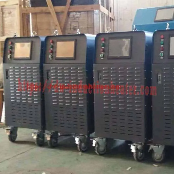
Engineering Selection Guide for Induction PWHT Machines
An induction PWHT machine must provide sufficient controllable heat to reach and maintain the specified temperature across the required heating zone.
Preliminary equipment sizing begins with the heated metal mass and sensible heat requirement.
However, real PWHT power demand also includes conduction into surrounding metal, convection, radiation, insulation losses and system losses.
1. Calculate the Heated Pipe Mass
For a simplified cylindrical pipe heating band:
V = π × (OD² − ID²) × L / 4
m = ρ × V
Where:
- V = volume of the heated pipe section, m³
- OD = pipe outside diameter, m
- ID = pipe inside diameter, m
- L = axial length of the heated band, m
- ρ = material density, kg/m³
- m = calculated metal mass, kg
Example: Carbon Steel Pipeline Weld Zone
| Engineering Parameter | Illustrative Value |
|---|---|
| Pipe Outside Diameter | 323.9 mm |
| Pipe Wall Thickness | 12.7 mm |
| Calculated Inside Diameter | 298.5 mm |
| Assumed Heated Band Length | 300 mm |
| Steel Density | 7,850 kg/m³ |
| Calculated Metal Mass | Approximately 29.2 kg |
This calculation treats the heating zone as a simple annular steel section. It excludes connected flanges, attachments, reinforcement, fixtures and adjacent metal heated through conduction.
2. Calculate the Sensible Heating Energy
The basic thermal energy equation is:
Q = m × cp × ΔT
Where:
- Q = sensible heating energy
- m = metal mass
- cp = average specific heat capacity
- ΔT = temperature rise
Example Calculation
| Parameter | Value |
|---|---|
| Heated Metal Mass | 29.2 kg |
| Assumed Average Specific Heat | 0.55 kJ/(kg·K) |
| Initial Temperature | 25°C |
| Illustrative Final Temperature | 575°C |
| Temperature Rise | 550 K |
Q = 29.2 × 0.55 × 550
Q ≈ 8,833 kJ ≈ 2.45 kWh
This represents the ideal sensible heat of the simplified steel band, not the total energy consumed by an actual PWHT machine.
3. Estimate Average Electrical Heating Power
For a first-pass estimate:
P = Q / (η × t)
Where:
- P = average electrical input power
- Q = sensible thermal energy
- η = assumed net useful energy fraction
- t = heating duration
Assuming an illustrative 50% net useful energy fraction:
| Heating Time | Calculated Average Electrical Input |
|---|---|
| 30 minutes | Approximately 9.8 kW |
| 45 minutes | Approximately 6.6 kW |
| 60 minutes | Approximately 4.9 kW |
| 90 minutes | Approximately 3.3 kW |
Important limitation: These are idealized average electrical input estimates for the specified metal band. The 50% factor is a calculation assumption, not a measured HLQ system efficiency.
Real power demand can be much higher because heat continually flows from the heated zone into adjacent metal. Additional power is also required to compensate for heat losses during the soaking period.
Therefore, selecting the MYD-40KW or any other model solely from this simplified calculation is not recommended.
4. Evaluate Heating and Insulation Width
For local PWHT, the heated band should cover the required weld and adjacent base-metal region according to the approved procedure.
The insulation band may extend beyond the controlled heating zone to limit temperature gradients.
| Design Parameter | Engineering Importance |
|---|---|
| Pipe Diameter | Determines circumference and coil arrangement |
| Wall Thickness | Affects thermal mass and through-wall temperature gradient |
| Heating Band Width | Determines the region receiving direct induction heating |
| Insulation Width | Influences heat loss and axial temperature gradients |
| Coil Turn Spacing | Affects electromagnetic coupling and heating distribution |
| Thermocouple Locations | Determine where process temperatures are measured and verified |
5. Evaluate Electrical Input Requirements
For a balanced three-phase system:
Pin = √3 × V × I × PF
Where:
- Pin = real electrical input power, W
- V = line-to-line RMS voltage, V
- I = line RMS current, A
- PF = total power factor
The electrical input rating and induction output rating are different quantities.
Electrical installation design must also consider generator efficiency, peak current, power factor, cable sizing, protection devices and applicable electrical regulations.
6. Select the Required Control and Recording System
| Control Feature | Why It Matters | Selection Requirement |
|---|---|---|
| Temperature Feedback | Controls workpiece temperature | Compatible with the selected thermocouples |
| Programmable Heating Profile | Controls ramp and soak stages | Must support the approved procedure |
| Multiple Temperature Measurements | Identifies temperature differences | Confirm the required number of measurement points |
| Independent Heating Zones | Controls different areas separately where necessary | Requires verified independent power-control capability |
| Temperature Recording | Provides treatment evidence | Recording intervals and calibration must be suitable |
| Process Alarms | Protects equipment and treatment quality | Configure permissible temperature and system limits |
7. Final Engineering Selection Checklist
| Required Information | Example Description |
|---|---|
| Material Grade | ASTM A106 Gr.B, P11, P22, P91 or other specified material |
| Workpiece Size | Pipe diameter, wall thickness and heated length |
| PWHT Procedure | Approved temperature, holding time, heating and cooling requirements |
| Heating Configuration | Flexible cable, coil arrangement and insulation |
| Production Demand | Number of joints and operating schedule |
| Temperature Monitoring | Number and locations of thermocouples |
| Electrical Supply | Voltage, phase, frequency and available feeder capacity |
| Cooling Arrangement | Available cooling method and site conditions |
| Quality Documentation | Temperature charts, inspection records and calibration information |
Advantages and Limitations of Induction PWHT Machines
Advantages
- Localized Heating: Heat can be concentrated in the required welded region.
- Non-Contact Energy Transfer: Electromagnetic induction generates heat in the conductive workpiece.
- Suitable for Large Components: Installed pipes and large structures may be treated without complete furnace loading.
- Programmable Temperature Control: Compatible control systems can execute defined thermal profiles.
- Temperature Recording: Data acquisition can support traceable heat-treatment documentation.
- Flexible Heating Arrangements: Induction cables can be adapted to different workpiece geometries.
- No Open Flame: Induction heating does not require direct combustion at the heating location.
- Automation Potential: Suitable systems can integrate temperature feedback, alarms and data management.
Limitations
- Application-Specific Engineering: Coil configuration and heating coverage must be designed for the actual workpiece.
- Thermal Gradients: Inadequate insulation or coil arrangement can cause uneven heating.
- Cooling Requirements: The power supply and induction cable may require different cooling arrangements.
- Electromagnetic Coupling: Heating efficiency depends on material properties and coil position.
- Equipment Investment: Induction heating systems require specialized electrical and control equipment.
- Process Qualification: Temperature control capability does not replace an approved PWHT procedure.
Comparison of PWHT Heating Methods
| Heating Method | Main Advantage | Main Limitation |
|---|---|---|
| Induction Heating | Localized heat generation with configurable coils | Requires electromagnetic and thermal design |
| Ceramic Resistance Heating | Adaptable pad arrangements and established field use | Pad contact, attachment and thermal losses require attention |
| Furnace Heating | Suitable for controlled treatment of complete components | Furnace size, transport and energy requirements |
| Gas-Fired Local Heating | Useful for selected large-scale heating arrangements | Combustion management and temperature uniformity requirements |
Energy consumption, heating time and achievable temperature uniformity should be compared under equivalent workpiece and process conditions rather than using unsupported universal percentage claims.
Why Choose HLQ Induction PWHT Equipment?
HLQ Induction Equipment Co., Ltd. supplies industrial induction heating equipment for applications including welding preheating, post weld heat treatment, stress relieving, brazing, forging, hardening and other thermal processes.
1. Published MYD Power Range
HLQ provides published MYD induction heating configurations in the 40–120 kW power classes.
2. Industrial Heating Applications
The published product portfolio covers pipeline heating, welding-related heat treatment, pressure vessel applications and other industrial heating requirements.
3. Flexible Heating Cable Options
Flexible induction cables and application-specific coil arrangements can accommodate different component geometries and field installation requirements.
4. Temperature Control and Monitoring
Depending on the selected configuration, MYD equipment can include digital controls, thermocouple connections and temperature recording functions.
5. Application-Oriented Engineering
System selection can be developed around the actual workpiece dimensions, required heating profile, electrical supply and production requirements.
6. Configurable Industrial Heating Solutions
HLQ’s product portfolio includes different induction heating arrangements for both stationary production facilities and suitable field applications.
Explore the related induction preheating and post welding heat treatment systems for additional equipment configurations.
Recommended Engineering Approach
The most suitable induction PWHT machine is not necessarily the machine with the highest rated power.
System selection should balance:
- Required thermal performance
- Temperature uniformity
- Material compatibility
- Heating and soaking duration
- Electrical power availability
- Cooling system capability
- Process repeatability
- Documentation requirements
- Site safety and installation conditions
Actual performance and final technical specifications should be confirmed through engineering review, current manufacturer documentation and application testing.
10 Core FAQs About Induction PWHT Machines
1. What is an induction PWHT machine?
An induction PWHT machine is a controlled heating system that uses electromagnetic induction to heat welded metal components according to a specified thermal cycle. It can be used for selected post weld heat treatment, stress relieving and welding preheating applications.
2. What is the purpose of post weld heat treatment?
Post weld heat treatment may reduce welding residual stresses, temper susceptible microstructures and help achieve required material properties. The actual objective and required thermal cycle depend on material grade, welding procedure, component thickness and governing construction code.
3. What temperature is required for PWHT?
There is no universal PWHT temperature. The prescribed temperature depends on the base metal, weld material, heat-treatment condition, applicable fabrication code and approved procedure. The MYD system’s published 900°C equipment limit must not be interpreted as a recommended PWHT temperature.
4. What power is required for a pipeline PWHT machine?
Required power depends on pipe diameter, wall thickness, heating-band width, material properties, heating time, insulation and heat losses. Preliminary energy calculations can estimate the thermal load, but final machine sizing requires consideration of heating losses and actual electromagnetic coupling.
5. What is the operating frequency of the MYD induction PWHT machine?
The published MYD series frequency range is 2–30 kHz. Actual frequency depends on the power supply, connected induction cable and workpiece characteristics. The operating frequency should be confirmed for the selected configuration.
6. Can induction PWHT be used for P91 and P22 steel?
Induction heating can be used to heat P91, P22 and other Cr-Mo steels. However, these materials require grade-specific heat-treatment procedures. Temperature, holding time, heating rate, cooling rate and metallurgical acceptance criteria must be verified before processing.
7. What is the difference between induction PWHT and resistance heating?
Induction heating generates heat through electrical currents induced in the conductive workpiece. Resistance heating generates heat in electrical heating elements and transfers it to the component. Both methods can perform PWHT when correctly engineered and operated under an approved procedure.
8. How many temperature control channels does an MYD PWHT machine have?
The original product information mentions six-channel monitoring or control capability. However, the number of thermocouple inputs must not be confused with the number of independently controlled heating power zones. The exact configuration should be verified for each MYD model.
9. How is the quality of induction PWHT verified?
PWHT quality is verified through the approved procedure, correct thermocouple placement, calibrated instruments, recorded heating and cooling profiles, specified temperature tolerances, and any additional inspections required by the project quality plan.
10. Can an induction PWHT machine automatically meet ASME requirements?
No. An induction heating machine is a tool used to execute a thermal treatment. Compliance with ASME or other applicable requirements depends on the governing code edition, approved PWHT procedure, equipment configuration, temperature measurement, process records and inspection results.