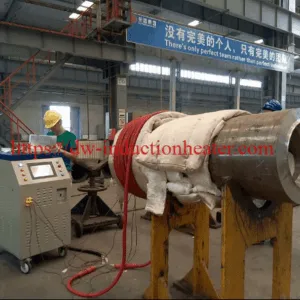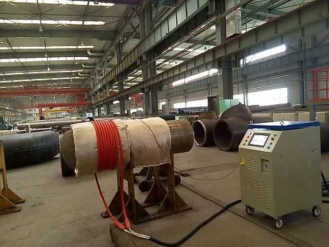





Induction PWHT System for Oil & Gas Pipeline Welding Projects
Induction PWHT System for Oil & Gas Pipeline Welding Projects | Engineering Selection Guide
Table of Contents
- Quick Answer
- What Is This Product?
- Key Applications
- Suitable Materials
- Working Principle
- Technical Specifications
- Recommended Model Selection
- Process Workflow
- Coil and Fixture Design
- Control System and Automation
- Common Problems and Solutions
- Engineering Selection Guide
- Advantages
- Limitations
- Why Choose HLQ Induction Equipment?
- Related Articles
- FAQ
The HLQ Induction PWHT System is a high-efficiency, field-deployable post weld heat treatment solution engineered specifically for oil and gas pipeline welding projects. It applies controlled electromagnetic induction heating to weld joints and heat-affected zones on carbon steel, alloy steel, chrome-moly, and P91 pipeline materials. Widely used in onshore and offshore pipeline construction, refinery piping, and pressure vessel fabrication, this system eliminates weld residual stresses, reduces hardness in the heat-affected zone, and ensures full compliance with ASME B31.3, ASME Section IX, and AWS D1.1 standards. For procurement engineers and welding contractors, it delivers faster cycle times, lower energy consumption, and precise digital temperature control compared to conventional resistance heating methods.
Quick Answer
An Induction PWHT System uses electromagnetic induction to rapidly and uniformly heat pipeline weld joints to prescribed soak temperatures — typically between 650°C and 760°C for carbon and alloy steels — and then controls the cooling rate to relieve residual stresses, improve toughness, and reduce hardness in the heat-affected zone. It is the best-fit solution for oil and gas pipeline projects that demand fast setup, precise temperature control, full data traceability, and compliance with international welding codes such as ASME B31.3, API 1104, and ISO 13916. Compared to resistance heating blankets, induction PWHT heats faster, consumes less energy, and delivers more uniform temperature distribution across the weld joint circumference.
What Is This Product?
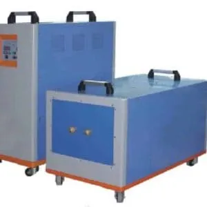
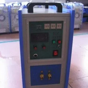
The Induction PWHT System is a complete post weld heat treatment station that integrates a solid-state induction power supply, flexible induction heating cables, multi-channel thermocouple temperature monitoring, a programmable PID temperature controller, and a digital data logger into a single portable or skid-mounted unit. Unlike traditional furnace-based PWHT, the induction system brings the heat source directly to the weld joint in the field, making it ideal for large-diameter pipelines, cross-country pipeline construction, and plant turnaround maintenance where moving components to a furnace is impractical or impossible.
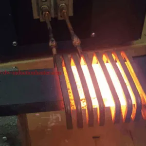
The system operates on the principle of electromagnetic induction: a high-frequency alternating current passes through a water-cooled induction coil or flexible cable wound around the pipe weld joint, generating eddy currents and hysteresis losses within the pipe wall that convert directly into heat. This internal heat generation mechanism produces extremely uniform, controllable, and repeatable thermal cycles that are fully recordable for code compliance documentation.
HLQ Induction PWHT Systems are available in power ranges from 15 kW to 360 kW, with operating frequencies from 1 kHz to 30 kHz, making them suitable for thin-wall small-bore tubing up to heavy-wall large-diameter transmission pipelines. All models support multi-zone simultaneous treatment, allowing multiple weld joints to be processed concurrently on a single power supply, dramatically improving project throughput and reducing equipment mobilization costs.
Key Applications
The Induction PWHT System serves a broad range of thermal treatment requirements across the oil and gas industry. Below are the primary application categories where this technology delivers the greatest engineering value:
- Onshore Pipeline Construction PWHT: Cross-country oil and gas transmission pipelines in carbon steel (API 5L X52, X60, X65, X70) require mandatory PWHT when wall thickness exceeds code-specified limits. Induction systems enable rapid joint-by-joint treatment directly in the trench or on the right-of-way without requiring a fixed heating station.
- Offshore and Subsea Pipeline Welding: Spool fabrication yards and offshore platform piping systems require PWHT in confined spaces and marine environments. The compact, weatherproof design of portable induction PWHT units makes them well-suited for platform decks, pipe lay barges, and fabrication workshops.
- Refinery and Petrochemical Plant Piping: High-temperature, high-pressure process piping in chrome-moly alloys (P11, P22, P91, P92) requires precise PWHT to restore creep resistance and prevent stress corrosion cracking. Induction systems provide the tight temperature uniformity (±15°C) demanded by ASME B31.3 for these critical alloys.
- Pressure Vessel and Heat Exchanger Fabrication: Shell-and-tube heat exchangers, pressure vessels, and reactor vessels require PWHT of nozzle welds, seam welds, and repair welds. Induction heating coils can be custom-designed to treat curved, flanged, and complex-geometry weld joints that resistance blankets cannot effectively cover.
- Pipeline Repair and Hot Tap Welding: In-service pipeline repair welds and hot tap sleeve installations require controlled preheat and PWHT to prevent hydrogen-induced cracking and ensure weld integrity. Induction systems allow precise local heating without disturbing adjacent pipe sections or coatings.
- Power Plant Boiler Tube and Header Welding: Boiler tube-to-header welds in high-alloy steels require PWHT cycles with slow, controlled heating and cooling rates. Multi-channel induction systems can treat multiple tube welds simultaneously, reducing outage duration during planned maintenance shutdowns.
- LNG Plant and Cryogenic Pipeline Fabrication: Stainless steel and duplex stainless steel piping in LNG facilities may require solution annealing or stress relief after welding. Induction systems provide the rapid, uniform heating needed for these heat-sensitive materials without the risk of oxidation associated with flame heating.
Suitable Materials
The Induction PWHT System is compatible with all ferromagnetic and electrically conductive pipeline materials. The following table summarizes the most common pipeline materials treated, their typical PWHT temperature ranges, and the applicable code requirements:
- Carbon Steel (API 5L Grade B, X42–X70; ASTM A106 Gr. B/C): PWHT soak temperature 595°C–650°C. Required when wall thickness exceeds 19mm (ASME B31.3) or as specified by WPS. Most common pipeline material in oil and gas transmission systems.
- Low Alloy Steel — 1.25Cr-0.5Mo (P11 / F11): PWHT soak temperature 675°C–760°C. Used in moderate-temperature refinery and power plant piping. Requires careful control of heating and cooling rates to avoid temper embrittlement.
- Low Alloy Steel — 2.25Cr-1Mo (P22 / F22): PWHT soak temperature 690°C–760°C. Widely used in high-temperature, high-pressure refinery and petrochemical service. PWHT is mandatory for all thicknesses per ASME B31.3.
- Advanced Alloy Steel — 9Cr-1Mo-V (P91 / F91): PWHT soak temperature 730°C–780°C. Critical power plant and refinery material requiring very precise temperature control (±10°C) and slow cooling rates. Induction systems with closed-loop PID control are strongly preferred for P91 PWHT.
- Advanced Alloy Steel — 9Cr-2W (P92 / F92): PWHT soak temperature 730°C–780°C. Next-generation creep-resistant steel for ultra-supercritical power plants. Requires the same precision PWHT approach as P91.
- Stainless Steel (ASTM A312 TP304, TP316, TP321): Solution annealing at 1050°C–1100°C or stress relief at 400°C–450°C. Induction heating is preferred to minimize sensitization risk by achieving rapid heating and cooling through the sensitization temperature range.
- Duplex and Super Duplex Stainless Steel (UNS S31803, S32750): Solution annealing at 1020°C–1100°C. Rapid, uniform heating is critical to maintain the balanced austenite/ferrite microstructure. Induction systems provide the heating rate control required.
- Nickel Alloy (Inconel 625, Alloy 825): Stress relief or annealing at 870°C–980°C. Used in sour service and subsea pipeline applications. Induction heating provides contamination-free, uniform treatment of these high-value materials.
Working Principle
The Induction PWHT System operates on Faraday’s Law of Electromagnetic Induction combined with the Joule heating effect. Understanding this principle is essential for engineers selecting and deploying the system correctly on pipeline projects.
Step 1 — Power Conversion: The system’s solid-state inverter power supply converts incoming three-phase AC mains power (typically 380V/415V/480V, 50/60 Hz) into a high-frequency alternating current in the range of 1 kHz to 30 kHz. The frequency is selected based on pipe wall thickness: lower frequencies (1–3 kHz) penetrate deeper into thick-wall pipe, while higher frequencies (8–30 kHz) are used for thin-wall tubing.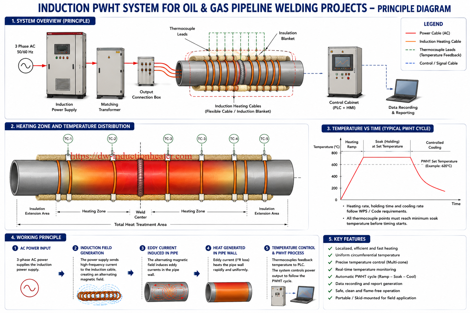
Step 2 — Magnetic Field Generation: The high-frequency current is delivered through water-cooled output cables to the induction heating coil or flexible induction cable wound around the pipe at the weld joint location. This current-carrying coil generates a rapidly alternating electromagnetic field that penetrates the pipe wall.
Step 3 — Eddy Current and Hysteresis Heating: The alternating magnetic field induces eddy currents within the electrically conductive pipe wall. These eddy currents flow in closed loops within the pipe material and generate heat through resistive (Joule) heating (I²R losses). In ferromagnetic materials (carbon steel, alloy steel), additional heat is generated by magnetic hysteresis losses as the magnetic domains repeatedly reverse alignment with the alternating field. Together, eddy current and hysteresis heating produce rapid, volumetric, internal heat generation within the pipe wall itself — not surface heating from an external flame or resistance element.
Step 4 — Temperature Monitoring and Control: Type K or Type R thermocouples are attached directly to the pipe surface at the weld joint and in the heat-affected zone. The thermocouple signals are fed to a multi-channel PID temperature controller that continuously compares actual pipe temperature against the programmed heating ramp rate, soak temperature, soak duration, and cooling rate. The controller automatically adjusts the inverter output power to maintain the programmed thermal cycle within the specified tolerance band (typically ±15°C for ASME compliance).
Step 5 — Thermal Insulation: Ceramic fiber insulation blankets are wrapped over the induction coil and the heated zone to minimize heat loss, improve temperature uniformity, reduce energy consumption, and ensure the required soak temperature is maintained across the full pipe circumference and through the pipe wall thickness.
Step 6 — Data Recording: The integrated data logger continuously records time-temperature data from all thermocouple channels throughout the PWHT cycle. This data is stored digitally and can be exported as a printed chart or electronic file (CSV, PDF) for inclusion in the weld quality documentation package required by ASME, API, and client inspection authorities.
Technical Specifications
HLQ Induction PWHT Systems are available in ten standard models covering the full range of pipeline diameters and wall thicknesses encountered in oil and gas projects. The table below summarizes the key technical parameters for each model:
| Model | Rated Power (kW) | Frequency Range (kHz) | Input Voltage | Max Output Current (A) | Temperature Channels | Max Temperature (°C) | Cooling Method | Unit Weight (kg) | Typical Pipeline Application | Notes |
|---|---|---|---|---|---|---|---|---|---|---|
| HLQ-PWHT-15 | 15 | 10–30 | 380V 3-phase | 40 | 4 | 1100 | Water-cooled | 85 | DN25–DN80 small-bore tubing | Portable; suitable for instrument tubing and small nozzle welds |
| HLQ-PWHT-30 | 30 | 8–25 | 380V 3-phase | 80 | 6 | 1100 | Water-cooled | 120 | DN50–DN150 process piping | Compact skid; ideal for refinery turnaround maintenance |
| HLQ-PWHT-60 | 60 | 4–15 | 380V 3-phase | 160 | 8 | 1200 | Water-cooled | 185 | DN100–DN300 pipeline | Most popular model for mid-size pipeline PWHT |
| HLQ-PWHT-80 | 80 | 3–12 | 380V 3-phase | 210 | 8 | 1200 | Water-cooled | 210 | DN200–DN400 transmission pipeline | Suitable for API 5L X65/X70 heavy-wall pipe |
| HLQ-PWHT-100 | 100 | 2–10 | 380V 3-phase | 260 | 12 | 1250 | Water-cooled | 260 | DN300–DN500 pipeline | Multi-zone capability; supports 2 simultaneous weld joints |
| HLQ-PWHT-120 | 120 | 2–8 | 380V 3-phase | 310 | 12 | 1250 | Water-cooled | 295 | DN400–DN600 large-diameter pipeline | Preferred for P22 and P91 chrome-moly pipeline PWHT |
| HLQ-PWHT-160 | 160 | 1–6 | 380V/415V 3-phase | 420 | 16 | 1300 | Water-cooled | 380 | DN500–DN800 transmission pipeline | High-power model for thick-wall large-diameter pipe |
| HLQ-PWHT-200 | 200 | 1–5 | 380V/415V 3-phase | 520 | 16 | 1300 | Water-cooled | 450 | DN600–DN1000 major transmission pipeline | Skid-mounted; supports 4 simultaneous weld zones |
| HLQ-PWHT-250 | 250 | 1–4 | 415V/480V 3-phase | 650 | 20 | 1350 | Water-cooled | 560 | DN800–DN1200 large-diameter pipeline | Suitable for offshore spool fabrication and major EPC projects |
| HLQ-PWHT-360 | 360 | 1–3 | 415V/480V 3-phase | 920 | 24 | 1400 | Water-cooled | 720 | DN1000–DN1400 ultra-large pipeline | Maximum power model; supports 6 simultaneous weld zones |
Recommended Model Selection
Selecting the correct induction PWHT system model depends on four primary factors: pipe outside diameter, wall thickness, material grade, and the number of weld joints to be treated simultaneously. The table below provides engineering-based model recommendations for the most common oil and gas pipeline scenarios:
| Application Scenario | Pipe Material | Pipe Size (OD × WT) | Recommended Model | Recommended Power | Frequency |
|---|---|---|---|---|---|
| Instrument tubing and small nozzle PWHT | ASTM A106 Gr.B / Carbon Steel | DN25–DN80 × 3–8mm | HLQ-PWHT-15 | 15 kW | 15–30 kHz |
| Refinery process piping PWHT | P11 / 1.25Cr-0.5Mo | DN100–DN200 × 8–15mm | HLQ-PWHT-60 | 60 kW | 6–12 kHz |
| High-temperature piping PWHT | P22 / 2.25Cr-1Mo | DN200–DN400 × 15–25mm | HLQ-PWHT-100 | 100 kW | 3–8 kHz |
| Critical alloy piping PWHT | P91 / 9Cr-1Mo-V | DN300–DN500 × 20–40mm | HLQ-PWHT-120 | 120 kW | 2–6 kHz |
| Onshore transmission pipeline PWHT | API 5L X65 / Carbon Steel | DN400–DN600 × 12–20mm | HLQ-PWHT-100 | 100 kW | 3–8 kHz |
| Large-diameter gas transmission pipeline | API 5L X70 / Carbon Steel | DN600–DN900 × 14–25mm | HLQ-PWHT-160 | 160 kW | 2–5 kHz |
| Offshore platform piping PWHT | Duplex SS / UNS S31803 | DN150–DN400 × 10–20mm | HLQ-PWHT-80 | 80 kW | 4–10 kHz |
| Major EPC pipeline project — multi-zone | API 5L X65/X70 / Carbon Steel | DN800–DN1200 × 18–30mm | HLQ-PWHT-250 | 250 kW | 1–4 kHz |
Process Workflow
A properly executed induction PWHT process on a pipeline weld joint follows a structured, code-compliant workflow. The following steps represent best practice for oil and gas pipeline applications in accordance with ASME B31.3 and API 1104:
- Pre-PWHT Inspection and Documentation: Verify that the weld joint has passed all required non-destructive examination (NDE) inspections — visual, radiographic (RT) or ultrasonic (UT), and magnetic particle (MT) or liquid penetrant (PT) as applicable. Review the approved Weld Procedure Specification (WPS) and PWHT procedure to confirm the required soak temperature, heating rate, soak duration, and cooling rate for the specific material and wall thickness.
- Surface Preparation: Clean the pipe surface in the weld zone and heat-affected zone to remove mill scale, rust, oil, grease, and any pipe coating within the heating band. The heating band width should extend at least 75mm (3 inches) on each side of the weld centerline, or 2× the pipe wall thickness on each side, whichever is greater, per ASME B31.3 requirements.
- Thermocouple Attachment: Attach Type K thermocouples to the pipe surface using capacitor discharge (CD) stud welding or high-temperature ceramic adhesive. For pipe circumferences up to 600mm, a minimum of 2 thermocouples per weld joint is required; for larger diameters, 4 or more thermocouples equally spaced around the circumference are recommended to verify temperature uniformity. Thermocouples should be positioned at the weld toe, the heat-affected zone, and the edge of the heating band.

- Induction Coil Installation: Wind the flexible induction heating cable around the pipe at the weld joint location. The number of turns, coil pitch, and heating band width are calculated based on the pipe diameter, wall thickness, and required power density. Ensure even spacing between cable turns to promote uniform circumferential temperature distribution. Secure the cable with high-temperature ceramic fiber rope or clips.
- Insulation Blanket Installation: Wrap ceramic fiber insulation blankets (minimum 25mm thickness, rated for ≥1260°C) over the induction coil and the full heating band. Extend the insulation at least 300mm beyond the heating band edges to minimize axial temperature gradients. Secure blankets with stainless steel banding or ceramic fiber rope.
- System Connection and Pre-Heat Check: Connect the induction cable to the power supply output terminals. Connect all thermocouple leads to the temperature controller input channels. Verify all connections are secure and the cooling water circuit is flowing correctly. Program the PWHT thermal cycle parameters into the temperature controller: heating rate (typically 100–200°C/hour for carbon steel, 50–100°C/hour for P91), soak temperature, soak duration, and cooling rate (typically ≤300°C/hour down to 300°C, then air cool).
- PWHT Cycle Execution: Start the PWHT cycle. The temperature controller automatically ramps the pipe temperature from ambient to the soak temperature at the programmed heating rate, holds at soak temperature for the required duration (typically 1 hour per 25mm of wall thickness, minimum 1 hour), then controls the cooling rate down to the specified temperature before allowing free air cooling. Monitor all thermocouple channels throughout the cycle to verify temperature uniformity.
- Post-PWHT Inspection: After the pipe has cooled to below 150°C, remove the insulation blankets and induction coil. Inspect the weld joint visually for any signs of distortion, cracking, or surface damage. Perform hardness testing (Vickers or Brinell) at the weld metal, heat-affected zone, and base metal to verify that the PWHT has achieved the required hardness reduction per the applicable code and WPS.
- Documentation and Reporting: Download the time-temperature chart from the data logger. Prepare the PWHT completion report including: joint identification, material, wall thickness, thermocouple positions, actual soak temperature achieved, soak duration, heating and cooling rates, hardness test results, and operator certification. This documentation package is submitted to the client’s QC inspector and retained as part of the permanent weld quality record.

Coil and Fixture Design
The design of the induction heating coil and its installation fixture is critical to achieving uniform temperature distribution across the weld joint. Poor coil design is the most common cause of temperature non-uniformity, which can lead to incomplete stress relief, code non-compliance, and weld joint rejection.
Flexible Induction Cable (Split Coil): For field pipeline PWHT, flexible water-cooled induction cables are the standard choice. These cables consist of a multi-strand copper conductor surrounded by high-temperature silicone insulation and a braided stainless steel outer jacket. They can be wound around any pipe diameter from DN25 to DN1400 without special tooling. The cable is supplied in standard lengths of 3m, 5m, and 8m, and multiple cables can be connected in series for large-diameter applications.
Coil Turn Calculation: The number of turns required is determined by the pipe diameter, wall thickness, and the power supply’s output impedance matching requirements. As a general guideline, 3–6 turns are used for pipe diameters up to DN300, while 6–12 turns are used for larger diameters. The coil pitch (spacing between turns) should be uniform and approximately equal to the cable outer diameter to maximize heating uniformity.
Heating Band Width: The heated band must be wide enough to ensure the full weld joint and heat-affected zone reach the required soak temperature. ASME B31.3 requires the heated band to extend at least 75mm or 2× wall thickness (whichever is greater) on each side of the weld centerline. For thick-wall pipe (WT > 25mm), a wider heating band may be required to achieve through-wall temperature uniformity.
Coil-to-Pipe Coupling Gap: The air gap between the induction cable and the pipe surface should be minimized to maximize electromagnetic coupling efficiency. A gap of 5–15mm is typical for field applications. Excessive gaps reduce heating efficiency and can cause localized hot spots at the cable positions.
Special Fixture Designs: For complex geometries such as elbow-to-pipe welds, tee branch connections, flange welds, and nozzle welds, custom-designed rigid or semi-rigid induction coil fixtures may be required. HLQ’s engineering team provides coil design support and can supply custom fixtures for non-standard pipeline configurations encountered in refinery and petrochemical plant piping systems.
Control System and Automation
The control system is the intelligence of the Induction PWHT System. HLQ systems are equipped with a multi-channel digital PID temperature controller with touchscreen interface, providing full automation of the PWHT thermal cycle with real-time monitoring and data recording capabilities.
PID Temperature Controller: The controller accepts inputs from up to 24 Type K or Type R thermocouples simultaneously. Each channel is independently controlled, allowing the system to compensate for temperature non-uniformity around the pipe circumference by automatically adjusting the power output to bring all zones to the target temperature. The controller supports programmable multi-segment thermal profiles with up to 32 ramp-and-soak segments per program, covering the most complex PWHT cycles required by ASME, EN, and other international codes.
Touchscreen HMI Interface: The 10-inch color touchscreen HMI displays real-time temperature curves for all active thermocouple channels, current power output level, elapsed cycle time, and remaining soak time. Operators can monitor the entire PWHT cycle at a glance and receive immediate visual and audible alarms if any thermocouple reading deviates from the programmed tolerance band.
Data Logger and Reporting: The integrated data logger records time-temperature data at user-selectable intervals (1 second to 1 minute). Data is stored on an internal solid-state memory module with capacity for over 10,000 hours of recording. Data can be exported via USB drive or Ethernet connection in CSV format for import into Microsoft Excel or dedicated PWHT reporting software. The system can also generate printed time-temperature charts directly from the front panel via an optional built-in thermal printer.
Remote Monitoring: HLQ PWHT systems support optional Wi-Fi and 4G LTE remote monitoring modules that allow project engineers and QC inspectors to monitor live PWHT cycle data from a laptop, tablet, or smartphone anywhere on the project site. This feature is particularly valuable for large pipeline projects where multiple PWHT stations are operating simultaneously across an extended right-of-way.
Alarm and Safety Systems: The control system includes comprehensive safety interlocks: over-temperature alarm and automatic power cutoff, cooling water flow and temperature monitoring, inverter over-current and over-voltage protection, thermocouple open-circuit detection, and emergency stop function. These protections ensure safe operation in the demanding field environments typical of oil and gas pipeline construction sites.
Common Problems and Solutions
Even with a well-designed induction PWHT system, field engineers occasionally encounter operational challenges. The following table identifies the most common problems and their recommended solutions:
| Problem | Likely Cause | Recommended Solution |
|---|---|---|
| Temperature non-uniformity around pipe circumference (>±25°C) | Uneven coil turn spacing; insufficient insulation; wind or draft cooling one side of pipe | Re-wind coil with uniform turn spacing; add additional insulation blanket layers; erect wind screens around the heated joint |
| Unable to reach soak temperature with full power output | Insufficient power for pipe size/wall thickness; excessive coil-to-pipe gap; inadequate insulation | Upgrade to higher-power model; reduce coil-to-pipe gap; increase insulation thickness; check for loose cable connections |
| Thermocouple reading unstable or erratic | Poor thermocouple attachment; damaged thermocouple lead; electromagnetic interference from induction field | Re-attach thermocouple using CD stud welder; replace damaged leads; use shielded thermocouple extension cables; route leads away from induction cable |
| Induction cable overheating | Insufficient cooling water flow; blocked cooling circuit; cable kinked or coiled too tightly | Check and restore cooling water flow rate (minimum 4 L/min); inspect for blockages; ensure cable bend radius exceeds minimum specification (typically 150mm) |
| Power supply inverter fault alarm | Input voltage fluctuation; output short circuit; internal component fault | Check input voltage stability; inspect output cables and coil for short circuits; contact HLQ technical support for inverter diagnostics |
| Hardness test after PWHT exceeds maximum limit | Soak temperature too low; soak duration insufficient; rapid cooling through critical temperature range | Review and verify thermocouple calibration; increase soak temperature within code limits; extend soak duration; control cooling rate more carefully |
| Data logger not recording / data loss | Memory full; USB drive not inserted; software fault | Clear old data from memory before starting new cycle; insert USB drive before cycle start; perform system restart and re-test data logging function |
Engineering Selection Guide
Selecting the right induction PWHT system for an oil and gas pipeline project requires a systematic engineering evaluation. The following decision framework guides procurement engineers and welding engineers through the key selection criteria:
- Define the Pipe Parameters: Establish the range of pipe outside diameters, wall thicknesses, and material grades that will require PWHT on the project. This determines the required power range, frequency range, and coil configuration. For projects with a wide range of pipe sizes, a mid-range model (80–120 kW) with adjustable frequency is often the most versatile choice.
- Determine the Required PWHT Temperature: Carbon steel requires soak temperatures of 595–650°C, while chrome-moly alloys (P11, P22) require 675–760°C, and P91/P92 require 730–780°C. Ensure the selected model’s maximum operating temperature exceeds the required soak temperature by at least 100°C to allow for heat losses and temperature gradients.
- Calculate the Required Power: As a practical rule of thumb, approximately 1.5–2.5 kW per kilogram of heated pipe mass is required to achieve typical PWHT heating rates. For a more precise calculation, HLQ’s engineering team can perform a thermal analysis based on the specific pipe geometry and material properties.
- Assess the Number of Simultaneous Weld Joints: On high-productivity pipeline projects, the ability to treat multiple weld joints simultaneously from a single power supply significantly improves project throughput. Select a model with sufficient power and temperature channels to support the required number of simultaneous zones.
- Evaluate Portability and Mobility Requirements: For cross-country pipeline construction, a compact, trailer-mounted or skid-mounted unit that can be rapidly relocated along the right-of-way is essential. For fixed plant maintenance, a larger, higher-power skid-mounted system may be more appropriate.
- Confirm Code and Documentation Requirements: Verify that the selected system’s data logger and reporting capabilities meet the documentation requirements of the applicable code (ASME B31.3, API 1104, EN 13480) and the client’s quality management system. Ensure the system can generate time-temperature charts in the format required by the client’s inspection authority.
- Consider Power Supply Availability: Confirm the available site power supply voltage and capacity. Most HLQ models operate on standard 380V or 415V three-phase power, but remote pipeline construction sites may require generator power. Ensure the site generator capacity is sufficient for the selected PWHT system plus all other site electrical loads.
Advantages
The Induction PWHT System offers a compelling set of technical and commercial advantages over conventional resistance heating and flame heating methods for oil and gas pipeline applications:
- Superior Heating Speed: Induction heating achieves heating rates of 200–500°C/hour, compared to 50–150°C/hour for resistance heating blankets. This reduces total PWHT cycle time by 40–60%, directly improving pipeline construction productivity and reducing project schedule risk.
- Excellent Temperature Uniformity: Internal volumetric heat generation by eddy currents produces more uniform through-wall and circumferential temperature distribution than surface-contact resistance heating. Temperature uniformity of ±10–15°C across the weld joint is routinely achieved, well within ASME B31.3 requirements.
- Higher Energy Efficiency: Induction PWHT systems typically achieve electrical-to-thermal efficiencies of 85–95%, compared to 60–75% for resistance heating blankets. This translates to significant energy cost savings on large pipeline projects with hundreds or thousands of PWHT joints.
- Non-Contact Heating: The induction coil does not physically contact the pipe surface, eliminating the risk of surface contamination, arc burns, or mechanical damage to pipe coatings adjacent to the weld zone. This is particularly important for pipelines with fusion-bonded epoxy (FBE) or three-layer polyethylene (3LPE) external coatings.
- Precise Automated Control: Closed-loop PID temperature control with multi-channel thermocouple monitoring ensures the programmed thermal cycle is executed precisely and repeatably, regardless of operator skill level. This reduces the risk of human error in PWHT execution and improves compliance with WPS requirements.
- Full Digital Traceability: Integrated data logging provides complete, tamper-proof time-temperature records for every PWHT joint, satisfying the documentation requirements of ASME, API, ISO, and client quality management systems without additional manual chart recording.
- Compact and Field-Deployable: Portable induction PWHT units are significantly more compact and lighter than equivalent-capacity resistance heating transformer sets, reducing transportation costs and enabling rapid deployment to remote pipeline construction locations.
- Safe Operation: Induction heating eliminates open flames and high-temperature resistance elements, reducing fire risk and burn hazard for field personnel. The induction cable surface temperature remains relatively low (typically below 80°C) even when the pipe is at PWHT temperature.


Limitations
While induction PWHT offers significant advantages, engineers should be aware of the following limitations when evaluating this technology for specific applications:
- Higher Initial Capital Cost: Induction PWHT systems have a higher purchase price than equivalent-capacity resistance heating transformer sets. However, the lower operating costs (energy savings, faster cycle times, reduced labor) typically result in a favorable total cost of ownership over the project life.
- Limited Effectiveness on Non-Ferromagnetic Materials: Induction heating is less efficient on non-ferromagnetic materials such as austenitic stainless steel, because hysteresis heating is absent and only eddy current heating contributes. Higher power and lower frequencies are required, and the achievable heating rate may be lower than for carbon or alloy steel of the same geometry.
- Coil Design Complexity for Non-Standard Geometries: While flexible induction cables can accommodate most standard pipe configurations, complex geometries such as large-bore tee intersections, multi-branch manifolds, and heavily contoured nozzle welds may require custom coil fixture design, adding engineering time and cost to the project.
- Cooling Water Requirement: All HLQ induction PWHT systems require a continuous cooling water supply to the induction cable and power supply. On remote pipeline construction sites, this requires either a portable water supply tank or a closed-loop chiller unit, adding to the equipment mobilization requirements.
- Operator Training Requirement: While the automated control system simplifies PWHT execution, operators must be trained in induction coil installation, thermocouple attachment, system programming, and safety procedures. Inadequately trained operators can produce non-compliant PWHT results even with a well-designed system.
- Electromagnetic Interference: The high-frequency electromagnetic field generated by the induction system can interfere with nearby electronic equipment, including welding machines, communication radios, and instrumentation. A minimum exclusion zone of 3–5 meters should be maintained around the operating induction PWHT system.
Why Choose HLQ Induction Equipment?
HLQ Induction Equipment has been a specialized manufacturer of industrial induction heating systems for over 20 years, with a proven track record of supplying induction PWHT systems to major oil and gas pipeline projects, refineries, petrochemical plants, and power generation facilities worldwide. Here is why leading EPC contractors and pipeline operators choose HLQ:
- 20+ Years of Induction Heating Expertise: HLQ’s engineering team has deep domain knowledge in induction PWHT system design, coil engineering, and process optimization for the full range of oil and gas pipeline materials and applications. This expertise is reflected in every aspect of our product design and customer support.
- Complete Product Range: From 15 kW portable units for small-bore tubing to 360 kW multi-zone systems for large-diameter transmission pipelines, HLQ offers the most comprehensive range of induction PWHT systems available from a single manufacturer, simplifying procurement and ensuring consistent performance across all project phases.
- ASME and API Code Compliance: All HLQ PWHT systems are designed and tested to meet the requirements of ASME B31.3, ASME Section IX, API 1104, EN 13480, and other major international welding and heat treatment codes. Our data logging and reporting systems generate documentation that satisfies the most stringent client and third-party inspection requirements.
- Custom Engineering Support: HLQ provides free pre-sales engineering consultation to help customers select the right system model and coil configuration for their specific project requirements. Our engineering team can perform thermal analysis, coil design calculations, and PWHT procedure development support for complex or non-standard applications.
- Global After-Sales Service Network: HLQ maintains a global network of trained service engineers and spare parts depots to support customers in all major oil and gas producing regions. Our 24/7 technical support hotline ensures that any operational issues are resolved quickly to minimize project downtime.
- Competitive Pricing and Flexible Supply Options: HLQ offers competitive factory-direct pricing on all standard models, with flexible supply options including outright purchase, long-term rental, and lease-to-own arrangements to suit different project budget structures and procurement policies.
Related Articles
- Induction Preheating System for Pipeline Welding: Complete Guide
- P91 Steel PWHT: Temperature Requirements, Procedures and Common Mistakes
- ASME B31.3 PWHT Requirements: What Every Pipeline Engineer Must Know
- Resistance Heating vs. Induction Heating for PWHT: A Technical Comparison
- How to Select the Right Thermocouple for Pipeline PWHT Applications
- Induction PWHT System for Pressure Vessel Fabrication: Engineering Guide
- Portable PWHT Equipment for Offshore Pipeline and Platform Applications
- Weld Residual Stress Relief: Mechanisms, Methods and Measurement
FAQ
Q1: What is the difference between induction PWHT and resistance heating PWHT?
Induction PWHT uses electromagnetic induction to generate heat internally within the pipe wall through eddy currents and hysteresis losses, while resistance heating uses electrical resistance elements (heating pads or blankets) placed on the pipe surface to conduct heat into the pipe from outside. Induction heating is faster (2–4× higher heating rates), more energy-efficient (85–95% vs. 60–75%), and produces more uniform through-wall temperature distribution. Resistance heating has a lower initial equipment cost but higher operating costs and longer cycle times.
Q2: What PWHT temperature is required for API 5L X65 carbon steel pipeline?
For API 5L X65 carbon steel pipeline, ASME B31.3 requires PWHT at a minimum soak temperature of 595°C (1100°F) when the nominal wall thickness exceeds 19mm (0.75 inch), or when required by the approved Weld Procedure Specification (WPS) regardless of thickness. The maximum soak temperature is typically limited to 650°C (1200°F) to avoid excessive softening of the base metal. The soak duration is a minimum of 1 hour per 25mm of wall thickness, with a minimum of 1 hour total.
Q3: How many thermocouples are required for pipeline PWHT per ASME B31.3?
ASME B31.3 does not specify a minimum number of thermocouples per weld joint, but industry best practice and most client specifications require a minimum of 2 thermocouples for pipe diameters up to DN300, and a minimum of 4 thermocouples equally spaced around the circumference for larger diameters. For critical alloy materials such as P91, 6 or more thermocouples are recommended to verify temperature uniformity within the ±15°C tolerance band required for these materials.
Q4: Can an induction PWHT system be used for P91 chrome-moly steel pipeline?
Yes, induction PWHT systems are well-suited for P91 (9Cr-1Mo-V) steel pipeline PWHT. P91 requires a soak temperature of 730–780°C with very tight temperature uniformity (±10°C is recommended by EPRI guidelines) and controlled heating and cooling rates. HLQ’s closed-loop PID temperature control system with multi-channel thermocouple monitoring is specifically designed to meet these demanding requirements. The HLQ-PWHT-120 model is the most commonly recommended system for P91 pipeline PWHT in the DN300–DN500 size range.
Q5: What is the typical PWHT cycle time for a carbon steel pipeline weld joint?
For a typical carbon steel pipeline weld joint (API 5L X65, DN400, wall thickness 16mm), the complete PWHT cycle using an induction system takes approximately 3–4 hours from ambient temperature: approximately 1.5–2 hours to heat from ambient to 620°C at 200–250°C/hour, 1 hour soak at 620°C, and approximately 1–1.5 hours of controlled cooling to 300°C at ≤300°C/hour, followed by free air cooling. This compares favorably with resistance heating, which typically requires 5–7 hours for the same joint.
Q6: Does the induction PWHT system require a special power supply on site?
HLQ induction PWHT systems operate on standard three-phase AC power at 380V, 415V, or 480V (50/60 Hz), which is the standard industrial power supply available at most pipeline construction sites and fabrication yards. For remote sites without grid power, a diesel generator of adequate capacity (typically 1.5× the rated system power) is required. HLQ can advise on generator sizing requirements for specific project conditions.
Q7: How is the PWHT data recorded and reported for code compliance?
HLQ induction PWHT systems include an integrated multi-channel data logger that continuously records time-temperature data from all thermocouple channels throughout the PWHT cycle. Data is stored in non-volatile memory and can be exported via USB drive or Ethernet connection in CSV format. The system can generate printed or electronic time-temperature charts that include joint identification, thermocouple positions, actual soak temperature, soak duration, heating and cooling rates, and operator information — all the data required for PWHT completion reports under ASME B31.3, API 1104, and most client quality management systems.
Q8: What is the service life of the induction heating cable (flexible coil)?
The service life of HLQ flexible induction heating cables depends on the frequency of use, operating temperature, and handling care. Under normal field conditions, a flexible induction cable typically provides 200–500 PWHT cycles before requiring replacement. Cable life can be extended by avoiding sharp bends below the minimum bend radius (150mm), preventing physical damage to the outer jacket, and ensuring adequate cooling water flow during operation. HLQ supplies replacement cables as standard spare parts with rapid worldwide delivery.