
Induction Straightening vs Flame Straightening for Bridges and Shipbuilding
Table of Contents
- Quick Answer
- Comparison Overview
- Working Principle Comparison
- Key Technical Parameters
- Efficiency and Energy Cost Comparison
- Temperature Control Comparison
- Material Quality and Surface Condition
- Safety and Compliance Comparison
- Maintenance Comparison
- Total Cost of Ownership
- Engineering Selection Guide
- Common Engineering Mistakes
- Common Problems and Solutions
- Real Project Case Study
- Honest Limitations of Both Methods
- Final Recommendation
- FAQ
This guide compares induction straightening and flame straightening for correcting distortion in steel bridges and ships: damaged or out-of-tolerance girders, flanges, decks, bulkheads and stiffened panels. Both methods use the same physics, local heating followed by controlled contraction. They differ in how the heat enters the steel, how repeatable the heat input is, what the work site needs and how hazards are controlled. The guide is written for bridge repair engineers, shipyard production and quality managers, and maintenance contractors who need a practical, honest basis for choosing a method or planning a trial. It uses published HLQ equipment data together with temperature limits from bridge heat-straightening guidance.
Quick Answer
Neither method is better in every case. Induction straightening suits repeated heating of decks, bulkheads and plates, where heat input should be set by power and time, no open flame is wanted and 380 V power and cooling water are available on site. Flame straightening suits occasional, access-limited or remote repairs where only gas supply is practical and a skilled operator is available. For both methods, the limiting factor is the steel, not the heat source. Bridge heat-straightening provisions that cite FHWA-IF-08-999 limit carbon steels to 1200 °F (about 650 °C) and quenched and tempered grades such as A514 and A709 Grade 100 to 1100 °F (about 593 °C).
Comparison Overview
Welding, cutting and impact damage leave steel structures distorted. In shipbuilding, thin deck and bulkhead plates buckle between stiffeners after welding. In bridges, girders and flanges are bent by fabrication distortion or by vehicle impact. Heat straightening corrects these shapes without cutting out and replacing steel.
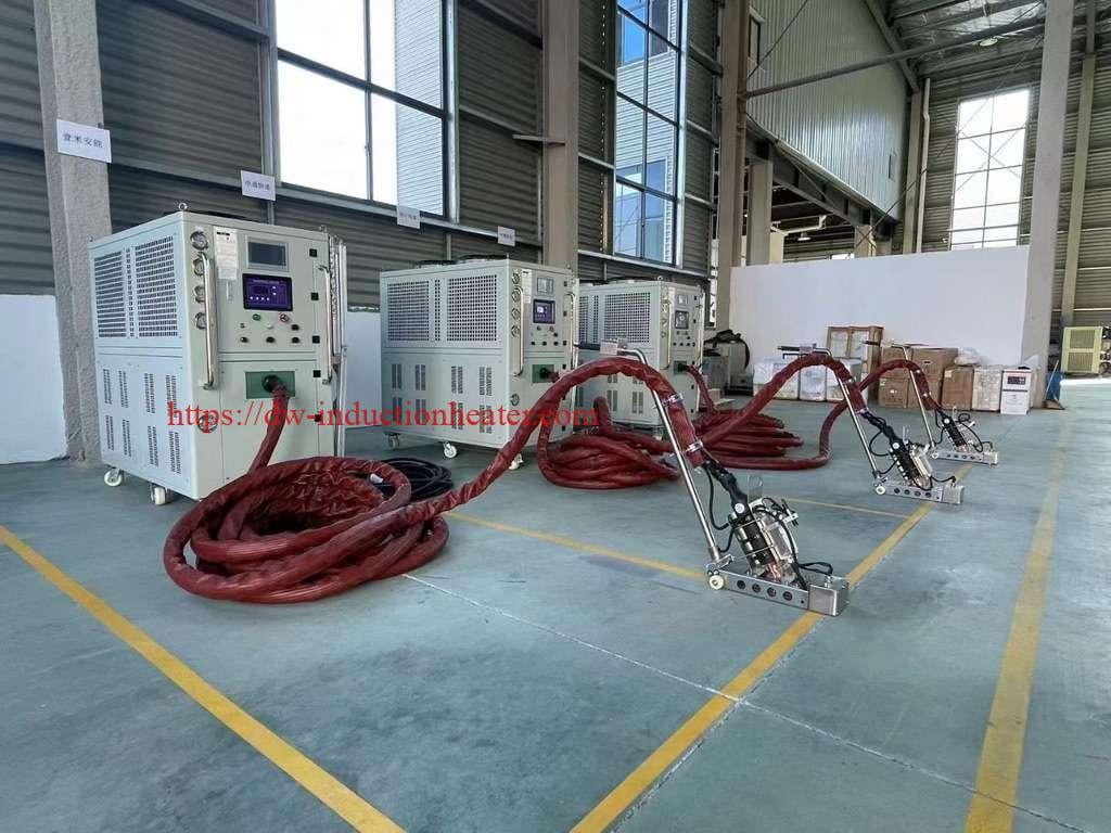
Flame straightening is the traditional method: a skilled operator moves an oxy-fuel torch along a heating pattern. Induction straightening replaces the flame with a water-cooled heating head connected to an induction generator. HLQ supplies induction equipment for this work, from handheld remote induction heaters to larger induction straightening heating machines.
Working Principle Comparison
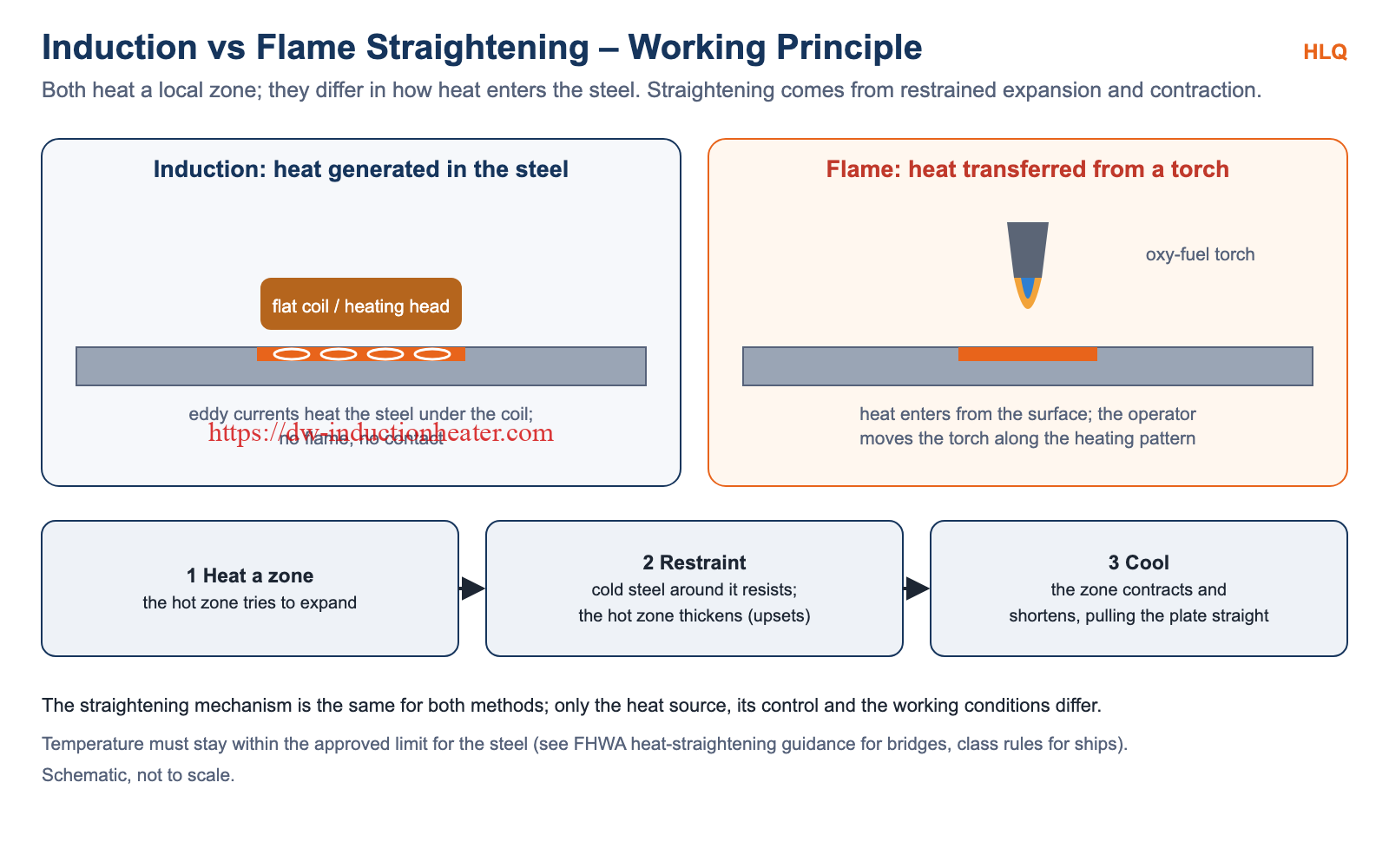
The straightening mechanism is the same for both methods:
- A local zone is heated and tries to expand.
- The surrounding cold steel restrains it, so the hot zone thickens (upsets) instead.
- On cooling, the upset zone contracts and becomes shorter than before, pulling the plate or member back toward its intended shape.
Spot, line and vee heating patterns decide where this shortening happens.
The difference is the heat source:
- Induction: alternating current in the coil induces eddy currents in the steel directly under the heating head, so the heat is generated inside the steel, without flame or contact.
- Flame: the torch heats the steel surface from outside, and the heat input depends on the torch tip, gas settings, stand-off distance and the operator’s travel speed.
Key Technical Parameters
| Parameter | Induction Straightening | Flame Straightening | Engineering Impact |
|---|---|---|---|
| Heat source | Eddy currents generated in the steel under the coil | Oxy-fuel flame heating the surface | Induction heat input is set by power and time |
| Heat input control | Power level and heating time per spot | Torch tip, gas flow, distance and travel speed | Repeatability between operators and shifts |
| Maximum steel temperature | Set by the steel’s approved limit | Set by the steel’s approved limit | The limit is the same for both methods |
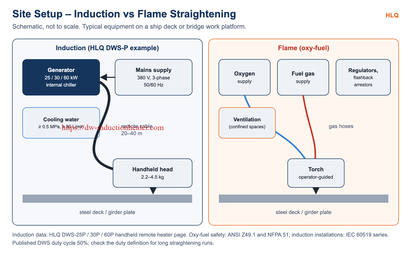
| Site utilities | 380 V 3-phase; cooling water ≥ 0.5 MPa, ≥ 30 L/min (HLQ DWS-P) | Oxygen and fuel gas supply | Plan power and water on deck or bridge, or gas logistics |
| Reach | 20 m (DWS-25P) or 20–40 m (DWS-30P/60P) remote cable | Gas hose length | Where the generator or cylinders can stand |
| Tool weight | Heating head 2.2–4.5 kg (DWS-P) | Hand torch | Operator fatigue on long runs |
| Power / frequency | 25–60 kW, 20–50 kHz (DWS-P handheld); 25–300 kW systems | Not applicable | Larger systems for thicker steel |
| Duty | Published duty cycle 50% (DWS-P) | Limited by operator and gas supply | Plan heating sequence and breaks |
| Open flame | None | Yes | Hot-work controls and fire watch for flame |
HLQ induction straightening system ranges (published):
| Parameter | Small system | Medium system | Large system |
|---|---|---|---|
| Power output | 25–50 kW | 50–100 kW | 100–300 kW |
| Frequency range | 5–15 kHz | 2–8 kHz | 0.5–5 kHz |
| Steel thickness capacity | Up to 15 mm | Up to 30 mm | Up to 60 mm |
| Cooling | Water-cooled, 10–15 L/min | Water-cooled, 20–40 L/min | Water-cooled, 40–80 L/min |
| Mobility | Portable / cart mounted | Semi-portable / wheeled | Fixed / crane assisted |
Efficiency and Energy Cost Comparison
Induction puts its energy into the steel under the heating head. A flame heats the surface from outside, and part of its heat goes into the surrounding air. How much useful heat each method delivers on site depends on coupling, plate thickness, heating pattern and duty, so a fair comparison needs a trial on the actual structure.
HLQ publishes an idealized area-rate example for its handheld systems. It assumes 50% utilization and 40% coupling, which gives an average useful power of 5, 6 and 12 kW for the DWS-25P, DWS-30P and DWS-60P:
| Model | Max. input power | Average useful power (example) | Idealized time per m² | Idealized area rate |
|---|---|---|---|---|
| DWS-25P | 25 kW | 5 kW | ≈ 369 s | ≈ 9.7 m²/h |
| DWS-30P | 30 kW | 6 kW | ≈ 308 s | ≈ 11.7 m²/h |
| DWS-60P | 60 kW | 12 kW | ≈ 154 s | ≈ 23.4 m²/h |
These are calculated examples, not measured straightening rates. Energy cost compares electricity for induction against oxygen and fuel gas for flame, so use your local tariffs and measured consumption from a trial.
Temperature Control Comparison
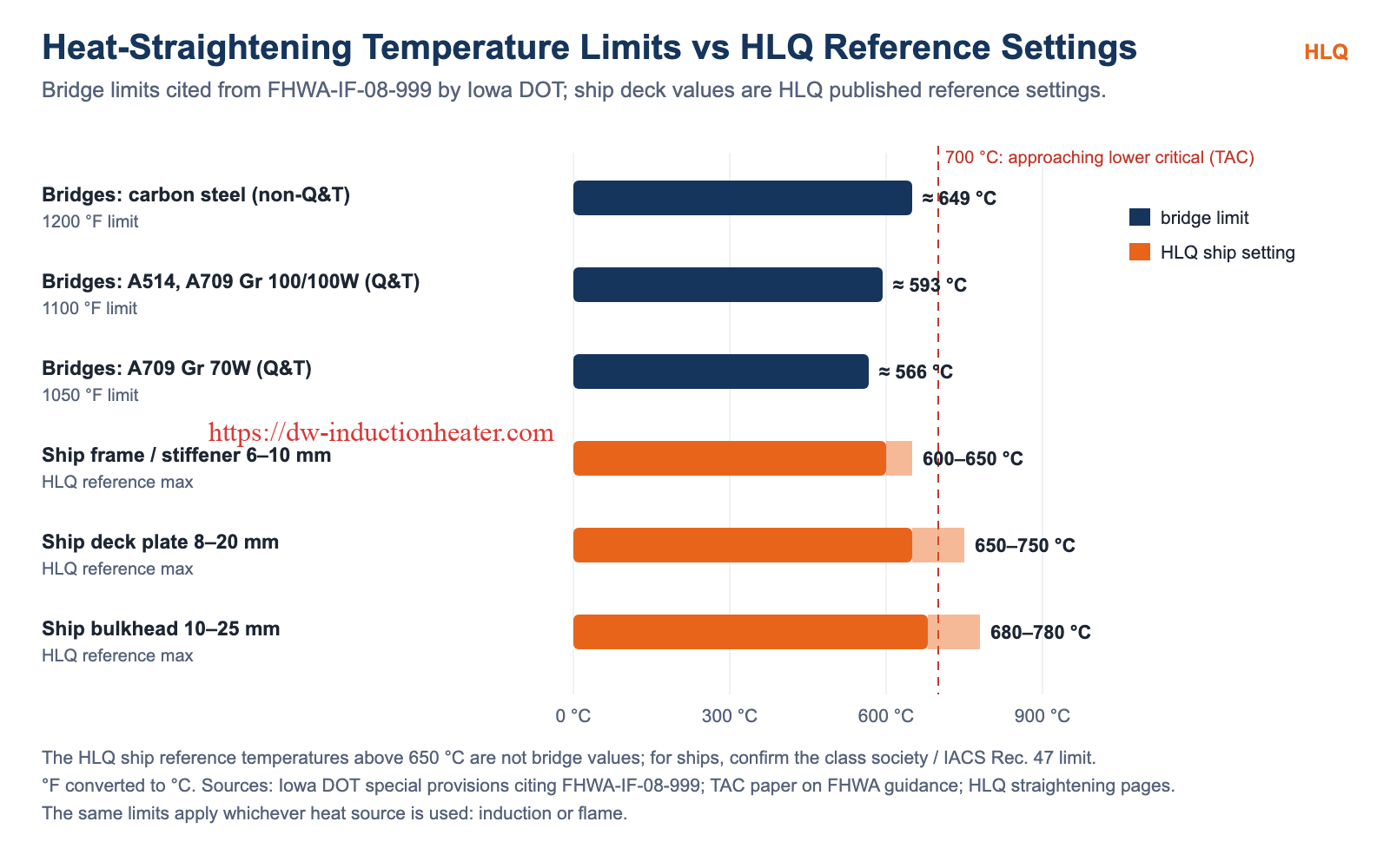
Temperature control is the most important engineering issue in heat straightening, whichever heat source is used. Iowa DOT special provisions citing FHWA-IF-08-999 set the following maximum steel temperatures for bridge members:
| Bridge steel | Maximum heat-straightening temperature |
|---|---|
| Carbon steels (not quenched and tempered) | 1200 °F (≈ 650 °C) |
| A514 and A709 Grades 100 and 100W (quenched and tempered) | 1100 °F (≈ 593 °C) |
| A709 Grade 70W (quenched and tempered) | 1050 °F (≈ 566 °C) |
A Transportation Association of Canada (TAC) paper on the FHWA guidance notes that steel temperatures above 700 °C start to approach the lower critical temperature. For ships, IACS Recommendation 47 (Shipbuilding and Repair Quality Standard) includes a provision on the maximum surface temperature for line heating, and the value must be confirmed with the classification society for the steel grade.
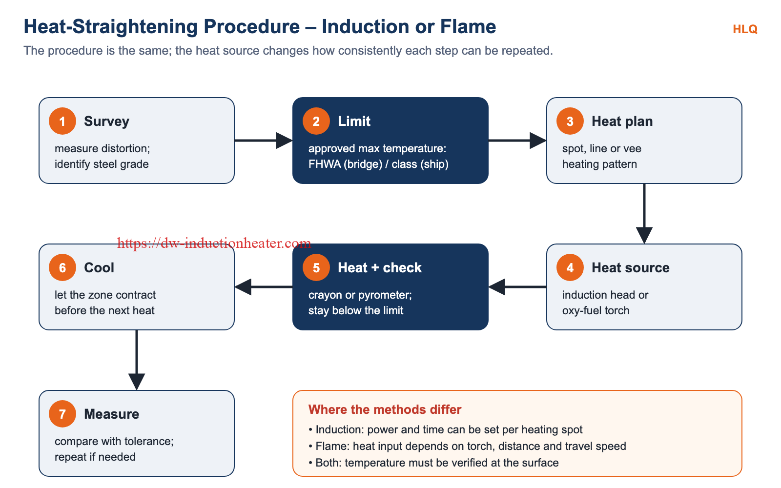
- Induction: power and heating time can be set and repeated for each spot. The equipment can heat well beyond these limits (HLQ systems list temperature ranges up to 800–1100 °C), so the approved limit must be set in the procedure and checked on the steel.
- Flame: the temperature reached depends on the operator’s torch handling, so it relies on skill and frequent checks.
- Both: verify the surface temperature with temperature-indicating crayons or a calibrated pyrometer with verified emissivity.
Material Quality and Surface Condition
When the temperature stays within the approved limit, the material outcome depends on the heating plan and the restraint, not on whether the heat came from a coil or a torch. The main quality risk for both methods is overheating. Exceeding the limit, especially when approaching the lower critical temperature, can change the steel’s properties, and high-strength quenched and tempered grades have lower limits.
Surface coatings are affected by both methods. HLQ uses the same induction technology to reduce coating adhesion for paint removal, so paint and coatings over the heated zone should be expected to need repair after straightening, whichever method is used. Flame heating also adds combustion products at the surface, while induction has none.

Safety and Compliance Comparison
| Topic | Induction | Flame |
|---|---|---|
| Main hazards | High voltage and current, cooling failure, electromagnetic field near the head, hot steel | Open flame, fuel gas leakage, fire, CO in confined spaces, hot steel |
| Key standards | IEC 60519 series (safety of electroheating installations) | ANSI Z49.1 (welding, cutting and allied processes), NFPA 51 (oxygen-fuel gas systems), NFPA 51B (hot work fire prevention) |
| Confined spaces | No combustion gases from heating | Ventilation and gas monitoring required |
| Site controls | Electrical isolation, cable routing, cooling water checks | Hot-work permit, fire watch, cylinder storage, flashback arrestors |
For a wider view of induction safety and process control in shipyards, see induction heating in shipbuilding and heavy machinery.
Maintenance Comparison
- Induction:
- Keep the cooling water within specification (HLQ DWS-P: at least 0.5 MPa and 30 L/min, with an internal chiller).
- Inspect the remote cable and heating head before each shift.
- Calibrate the temperature measurement.
- Respect the published duty cycle.
- Flame:
- Inspect hoses, regulators, torch and flashback arrestors as required by oxy-fuel safety standards.
- Manage gas cylinder supply and storage.
- Maintain torch tips so the flame stays consistent.
Total Cost of Ownership
Compare the total cost over the planned workload rather than the purchase price alone:
- Equipment: an induction generator, cables and heads cost more to buy than torch sets.
- Running cost: electricity for induction against oxygen and fuel gas for flame, at local prices.
- Labour: operator time per square metre or per heat, and the skill level needed.
- Rework: repeated heats and over-correction caused by inconsistent heat input.
- Safety measures: hot-work permits, fire watch and ventilation for flame; electrical and cooling infrastructure for induction.
- Utilization: how many days per year the equipment is actually used.
Low-volume or occasional repair work often favours flame. Continuous shipyard straightening often justifies induction.
Engineering Selection Guide
| Condition | Recommended Option | Reason |
|---|---|---|
| Continuous straightening of ship decks and bulkheads in a yard | Induction | Repeatable heat input per spot, no open flame, high utilization |
| Confined spaces such as double bottoms and tanks | Induction | No combustion gases from heating |
| Occasional repair at a remote bridge site without suitable power | Flame | Needs only gas supply; quick to deploy |
| Quenched and tempered bridge steel (A514, A709 Gr 100) | Either, with strict temperature control | Lower limit of 1100 °F; consistent heat input helps stay below it |
| Thick flanges and heavy members | Larger induction system or flame, after a trial | Handheld systems may not deliver enough heat; HLQ large systems up to 60 mm thickness |
| Hot-work restrictions on site | Induction | No open flame, subject to the site’s own rules |
| Very complex shapes with poor access | Flame | A torch reaches places a heating head may not |
For bridge and building structures, see straightening of construction and structural engineering with induction heating.
Common Engineering Mistakes
- Treating the equipment’s capability as the process temperature: the approved steel limit governs, not the maximum the system can reach.
- Not identifying the steel grade: quenched and tempered grades have lower limits than carbon steels.
- Measuring temperature without verified emissivity: pyrometer readings on scaled or painted steel can be wrong.
- Applying excessive jacking force: bridge provisions limit external restraint forces relative to the member’s capacity.
- Re-heating before the previous heat has cooled: measure between heats.
- Ignoring site utilities and duty cycle: power, cooling water and the published 50% duty of DWS-P units decide the real working rate.
- Skipping a trial: heating patterns and settings should be confirmed on the actual plate thickness and restraint.
Common Problems and Solutions
| Problem | Likely Cause | Solution |
|---|---|---|
| Little or no straightening effect | Wrong heating pattern or too little restraint | Review the spot, line or vee pattern and the restraint plan |
| Over-correction | Too many or too large heats | Measure after each heat and reduce the heat size |
| Temperature above the limit | Heat input too high or not checked | Lower the power or time (induction) or adjust the torch technique (flame); check every heat |
| Inconsistent results between operators | Variable manual heat input | Use set power and time per spot (induction) and a written procedure |
| Induction head not heating evenly | Coil-to-steel gap varies; coating or scale | Keep a constant gap; check the head and surface |
| Induction unit stops during long runs | Duty cycle or cooling limits reached | Plan breaks within the duty cycle; check water pressure and flow |
Real Project Case Study
HLQ publishes reference settings for induction straightening of ship decks, bulkheads and frames. They show how power and heating time scale with plate thickness and are intended as starting points to be confirmed by a trial:
| Application | Thickness (mm) | Power (kW) | Heating time (s) | Max. temperature (°C) |
|---|---|---|---|---|
| Deck plate | 8 | 40 | 45–60 | 650 |
| Deck plate | 12 | 60 | 70–90 | 700 |
| Deck plate | 20 | 100 | 120–150 | 750 |
| Bulkhead | 10 | 50 | 60–75 | 680 |
| Bulkhead | 15 | 80 | 90–110 | 720 |
| Bulkhead | 25 | 160 | 180–210 | 780 |
| Frame / stiffener | 6 | 30 | 30–45 | 600 |
| Frame / stiffener | 10 | 55 | 50–70 | 650 |
Several of these shipbuilding settings exceed 650 °C. They must not be used for bridge members, and for ships they must be checked against the classification society’s line-heating limit before use. The site photographs in this article show HLQ handheld induction systems working on ship decks and steel structures. Customer-specific before-and-after measurements are available on request for qualified projects. More detail: induction straightening of bulkheads and decks and induction straightening in the shipbuilding and marine industry.

Honest Limitations of Both Methods
- Induction:
- Needs 380 V 3-phase power and cooling water at the work area.
- The heating head must sit close to a reasonably flat surface.
- Handheld units have a 50% published duty cycle and limited heat for very thick members.
- The investment is higher.
- Flame:
- Heat input depends on operator skill.
- Requires hot-work controls, fire watch and ventilation, especially in confined spaces.
- Gas logistics and cylinder storage must be managed.
- Results vary more between operators.
- Both:
- Neither method removes the need for an approved temperature limit, a heating plan, surface temperature checks and dimensional measurement.
- Coatings over heated zones need repair.
Final Recommendation
- Choose induction straightening where straightening is regular work, where heat input should be repeatable and documented, where open flames are restricted, and where power and cooling water can be provided. This typically means shipyard deck and bulkhead production, repair yards and fabrication shops.
- Keep flame straightening for occasional, remote or access-limited repairs, such as one-off bridge impact damage at sites without suitable power.
For both methods, start from the approved temperature limit of the steel, use a written heating plan and verify each heat. A short trial on representative plate is the most reliable way to confirm settings and working rate before committing to equipment.
FAQ
Is induction straightening better than flame straightening?
It is better where repeatable heat input, no open flame and high utilization matter. Flame remains practical for occasional or remote work.
Does induction allow higher straightening temperatures?
No. The steel’s approved limit applies to both methods; for bridge carbon steels, provisions citing FHWA guidance set 1200 °F (about 650 °C).
What is the limit for quenched and tempered bridge steels?
1100 °F (about 593 °C) for A514 and A709 Grades 100 and 100W, and 1050 °F (about 566 °C) for A709 Grade 70W, per Iowa DOT provisions citing FHWA-IF-08-999.
Can induction be used on bridge girders?
Yes, within the approved temperature limits and heating plan. Heavy flanges may need larger induction systems and should be confirmed by a trial.
What does an induction straightening site need?
380 V 3-phase power and cooling water. HLQ DWS-P handheld systems need at least 0.5 MPa and 30 L/min of water and work up to 20–40 m from the generator.
How is temperature checked during straightening?
With temperature-indicating crayons or a calibrated pyrometer with verified emissivity, after every heat.
Which safety standards apply?
The IEC 60519 series for induction heating installations; ANSI Z49.1, NFPA 51 and NFPA 51B for oxy-fuel and hot work.
How thick can induction straighten?
HLQ lists system capacities of up to 15 mm (small), 30 mm (medium) and 60 mm (large) steel thickness, to be confirmed for each structure.
HLQ-Induction-vs-Flame-Straightening-Bridges-Shipbuilding