
Induction Preheating for Welding Structural Steel, Pipes, and Steel Strips
Induction preheating for welding is an industrial heating process that uses electromagnetic induction to raise the temperature of conductive metal components before welding begins.
It is widely applicable to suitable structural steel components, steel pipe joints, fabricated assemblies, and selected steel strip welding operations.
Induction preheating generates heat within the metal rather than relying entirely on heat transferred from an external flame or resistance element. With an appropriately designed induction coil and temperature-monitoring system, the process can provide controlled localized heating for industrial welding preparation.
However, structural steel, steel pipes, and steel strips require different heating arrangements. Their thermal masses, dimensions, operating conditions, and production methods determine the most suitable induction equipment.
This engineering guide explains the working principle, materials, industrial applications, induction power supplies, heating coil arrangements, technical calculations, model selection, process workflow, troubleshooting, and important limitations.
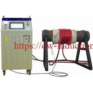
What Is Induction Preheating for Welding?
Induction preheating for welding uses a high-frequency electromagnetic field to generate heat inside steel before welding. It can be used to establish the minimum preheat temperature specified by an approved welding procedure specification (WPS).
For susceptible steels, correctly applied preheating can slow weld cooling and help reduce conditions associated with hydrogen-assisted cracking.
Induction preheating is used for structural steel fabrication, steel pipe welding, pressure-component repairs, strip-end butt welding, and selected steel strip edge-heating applications.
HLQ offers published industrial MYD induction heating models with nominal ratings from 40 kW to 120 kW. Its website also describes custom induction strip heating systems for continuous manufacturing lines.
Equipment selection depends on: steel grade, geometry, thickness, target temperature, heated area, heating time, operating frequency, production speed, induction coil design, and temperature-control requirements.
Quick Engineering Comparison
| Application | Heating Configuration | Primary Selection Parameters | Temperature Measurement |
|---|---|---|---|
| Structural Steel Welding | Localized induction coil or compatible flexible heating cable | Heated steel mass, weld geometry, plate thickness, heating time | Thermocouples at specified metal-surface locations |
| Steel Pipe Welding | Flexible induction cable around an insulated pipe | Pipe OD, wall thickness, heating-band width, target temperature | Thermocouples directly contacting the steel beneath the insulation |
| Steel Strip Butt Welding | Application-specific local induction coil | Strip width, thickness, local heating zone, welding cycle | Suitable contact or non-contact measurement |
| Continuous Steel Strip Heating | Inline longitudinal-flux, transverse-flux, or edge-heating coils | Strip width, gauge, line speed, heated width, thermal power | Often non-contact temperature measurement with speed feedback |
Important distinction: Welding preheating is not the same as post-weld heat treatment or steel strip annealing. Each process has different metallurgical objectives and temperature-control requirements.
Table of Contents
- What Is Induction Preheating for Welding?
- Key Applications
- Suitable Materials
- Working Principle
- Technical Specifications
- Recommended Model Selection
- Process Workflow
- Common Problems and Solutions
- Engineering Selection Guide
- Advantages and Limitations
- Why Choose HLQ?
- 8 Core FAQs
What Is Induction Preheating for Welding?
Induction preheating is a controlled metal-heating process performed before welding to achieve the temperature required by the relevant welding procedure.
An induction heating generator supplies alternating electrical current to an induction coil. The resulting magnetic field induces electrical currents within the conductive workpiece, producing heat through electrical resistance.
Because heat is generated within the metal, induction heating can provide effective localized heating when the coil geometry and operating conditions are correctly selected.
Why Is Preheating Required Before Welding?
Some steels and welded structures are susceptible to cracking when welding conditions produce rapid cooling, high restraint, susceptible microstructures, and diffusible hydrogen.
Preheating can help manage these conditions by reducing temperature gradients and changing the cooling behavior of the heat-affected zone.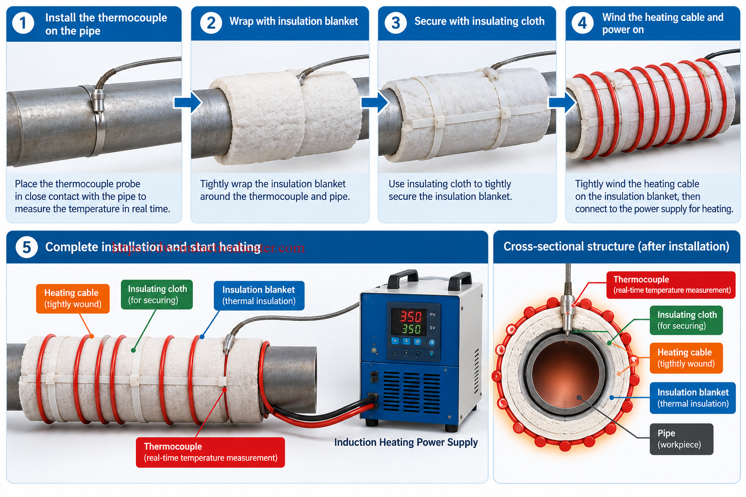
Nevertheless, preheating does not eliminate every welding defect or compensate for an unsuitable welding procedure.
The required temperature depends on the steel grade, carbon equivalent, thickness, hydrogen control, joint restraint, welding consumables, and applicable welding standard.
Preheating, Interpass Heating, and PWHT
| Process | When Performed | Primary Objective | Critical Control |
|---|---|---|---|
| Weld Preheating | Before welding | Establish the specified base-metal temperature | Minimum preheat temperature |
| Interpass Temperature Control | Between welding passes | Maintain welding temperature within approved limits | Minimum and maximum interpass temperatures |
| Postheating | After welding, when specified | Apply an approved post-weld heating or holding process | Temperature and holding time |
| Post-Weld Heat Treatment | After welding | Apply a qualified thermal treatment | Heating rate, holding temperature, time, cooling rate, and records |
Main Components of an Induction Welding Preheating System
| Equipment Component | Function | Engineering Consideration |
|---|---|---|
| IGBT Induction Power Supply | Generates controlled high-frequency electrical power | Rated output, frequency, operating duty, input supply |
| Induction Heating Coil | Generates the alternating magnetic field | Geometry, conductor construction, cooling, coupling |
| Flexible Induction Cable | Allows suitable coil arrangements around steel pipes and structures | Cable length, number of turns, insulation, electrical matching |
| PLC Temperature Controller | Provides supported heating control functions | Control channels, temperature limits, alarms |
| Thermocouples | Measure selected metal-surface temperatures | Contact quality, placement, calibration |
| Infrared Pyrometer | Measures temperature without contacting moving steel | Emissivity, measurement angle, surface condition |
| Thermal Insulation Blanket | Reduces heat loss for suitable stationary heating applications | Temperature rating, thickness, installation |
| Non-Metallic Insulating Straps | Secure insulation and approved heating arrangements | High-temperature resistance and electrical insulation |
| Cooling System | Controls operating temperatures of specified equipment components | Airflow, water flow, ambient conditions, duty cycle |
Key Applications
1. Induction Preheating for Structural Steel Welding
Structural steel welding often involves heavy plates, beams, box sections, columns, bridge components, and other fabricated assemblies.
Depending on the material and welding procedure, these components may require preheating before welding begins.
Induction heating can be applied to selected welded regions using appropriately designed coils or compatible flexible heating cables.
For thick structural components, the heating arrangement must account for thermal conduction into surrounding material, joint restraint, temperature gradients, and the actual heated mass.
Typical Structural Steel Applications
| Structural Component | Heating Objective | Important Design Factor |
|---|---|---|
| H-Beams and I-Beams | Preheat selected flange or web weld regions | Joint shape and temperature distribution |
| Heavy Steel Plates | Raise the temperature around the welding groove | Plate thickness and heated-zone width |
| Box Columns | Condition specified weld regions before fabrication | Accessibility and heat conduction |
| Bridge Components | Follow specified welding preheat requirements | Steel grade, restraint, and welding procedure |
| Large Welded Frames | Provide localized preheating during fabrication | Irregular geometry and coil placement |
| Industrial Weld Repairs | Establish approved repair-welding temperatures | Material condition and qualified repair procedure |
For larger fabrication projects, HLQ also provides related structural steel welding preheat systems and welding heat-treatment equipment.
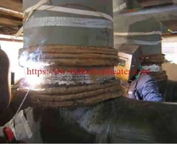
2. Induction Preheating for Steel Pipe Welding
Steel pipelines frequently require controlled heating around circumferential weld joints.
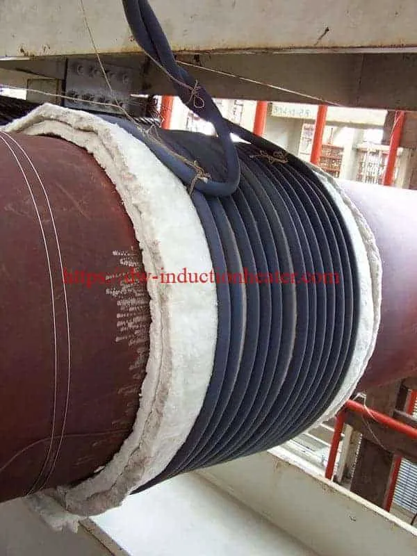
Induction heating cables can be wrapped around suitable insulated pipe sections to produce an alternating magnetic field that heats the underlying steel.
Compared with small discrete metal components, pipe preheating requires careful control of heating-band width, circumferential temperature distribution, and axial conduction into adjacent pipe sections.
Important parameters include pipe outside diameter, wall thickness, steel grade, initial temperature, target temperature, and permitted heating time.
Pipe Welding Applications
| Industry | Typical Component | Important Requirement |
|---|---|---|
| Oil and Gas | Transmission pipelines and welded fittings | Approved welding temperature and field safety |
| Petrochemical | Process piping | Material-specific welding procedure |
| Power Generation | Industrial steam piping | Steel grade and wall thickness |
| Shipbuilding | Steel pipe assemblies | Accessibility and coil arrangement |
| Industrial Maintenance | Repair weld joints | Qualified repair procedure and isolation |
For detailed pipe sizing and industrial heating arrangements, review HLQ pipeline induction preheating systems.
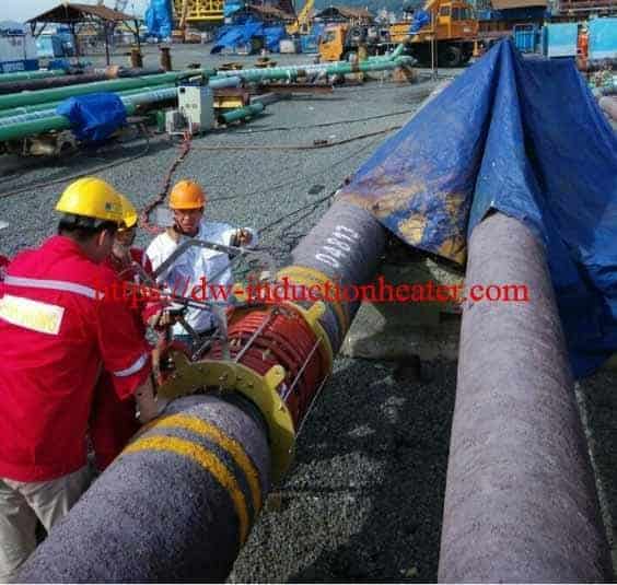
3. Induction Preheating for Steel Strip Welding
Steel strip welding applications require a different heating strategy from stationary structural steel and pipe joints.
Steel strips may be processed as individual lengths, coil ends, or continuously moving material.
Depending on the production process, induction heating may be used for local strip-end heating, heating adjacent to a butt-weld joint, or selective heating of strip edges before subsequent joining operations.
Three Different Steel Strip Heating Applications
| Application | Heating Method | Critical Parameters |
|---|---|---|
| Strip-End Butt Welding | Localized induction coil near stationary strip ends | Strip width, thickness, weld-zone dimensions, welding cycle |
| Tube-Mill Strip Edge Preheating | Edge-focused induction heating arrangement | Line speed, heated edge width, forming geometry |
| Continuous Full-Width Strip Preheating | Inline longitudinal-flux or transverse-flux coil | Strip width, gauge, line speed, temperature rise |
Strip-edge preheating should not be confused with the actual high-frequency seam-welding process, which requires its own welding-energy design.
Likewise, full-width strip preheating should not automatically be described as strip annealing.
For dedicated continuous processing applications, review HLQ induction strip heating equipment and associated coil technologies.
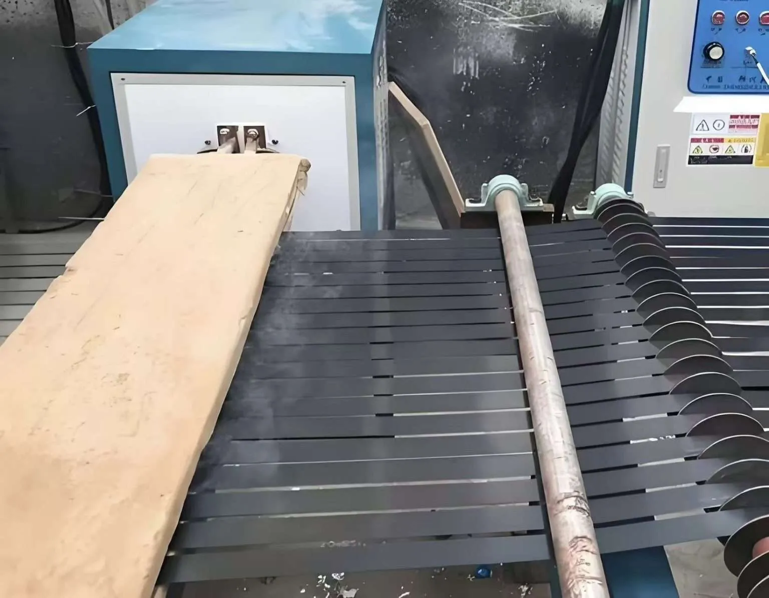
4. Steel Strip Edge Heating Before Tube Forming and Welding
In continuous tube production, flat steel strip is progressively formed into a tubular shape before the longitudinal seam is welded.
Where the process calls for preliminary temperature adjustment, an edge-focused induction arrangement can heat selected regions near the future weld seam.
Only the required edge regions should be included in the initial thermal-load calculation when the process does not require full-width heating.
The final coil configuration must account for the strip edge geometry, line speed, forming sequence, distance from the welding point, and temperature loss during transport.
5. Structural Weld Repair
Some repair-welding procedures require heating around the repair location before welding.
Induction heating may be suitable for accessible steel components when the required heating region and temperature can be controlled.
Repair welding should follow the approved material-specific procedure rather than relying on generic preheat recommendations.
6. Welding Preheating for Thick Steel Sections
Thicker sections have greater thermal mass and may require more energy to achieve the specified temperature.
They can also conduct heat away from the selected heating zone.
Engineering calculations should therefore include the intended heated mass, reasonable allowances for adjacent material, and the heating duration.
Suitable Materials
Induction welding preheating is applicable to electrically conductive metal components.
Material suitability depends on electromagnetic properties, thermal properties, welding requirements, and the component’s heat-treatment condition.
Material Compatibility Matrix
| Material | General Induction Heating Suitability | Welding Preheat Consideration |
|---|---|---|
| Low-Carbon Steel | Generally Suitable | Preheat requirements depend on the applicable WPS |
| Structural Carbon Steel | Generally Suitable | Thickness, restraint, and hydrogen control |
| Pipeline Carbon Steel | Generally Suitable | Grade, wall thickness, and welding procedure |
| Low-Alloy Steel | Application-Dependent | Grade-specific preheat limits |
| Cr-Mo Alloy Steel | Conditional | Detailed preheat and possible PWHT requirements |
| Quenched and Tempered Steel | Conditional | Maximum permissible heating temperature |
| Ferritic Stainless Steel | Application-Dependent | Magnetic behavior and qualified welding procedure |
| Austenitic Stainless Steel | Requires Evaluation | Different electromagnetic coupling and welding requirements |
| High-Carbon Steel Strip | Conditional | Hardness, cracking sensitivity, and metallurgical condition |
| Electrical Steel Strip | Specialized Application | Coating condition and temperature-sensitive properties |
Properties Influencing Heating Performance
| Material Property | Effect on Induction Heating |
|---|---|
| Electrical Resistivity | Influences resistive losses from induced electrical currents |
| Magnetic Permeability | Affects electromagnetic coupling and current penetration |
| Thermal Conductivity | Determines the redistribution of heat within steel |
| Specific Heat Capacity | Determines the energy required for a temperature increase |
| Wall or Plate Thickness | Affects heated metal mass and temperature gradients |
| Initial Temperature | Determines the required temperature rise |
| Heat Treatment Condition | May limit allowable heating temperatures |
Material safety note: The correct preheat temperature must come from the applicable WPS, material specifications, and engineering requirements. There is no universal preheat temperature suitable for every steel grade.
Working Principle
How Does Induction Preheating Work?
Induction heating is based on electromagnetic induction.
When alternating current flows through an induction coil, it generates a time-varying magnetic field.
When a conductive steel workpiece is exposed to the field, electrical currents are induced within the metal.
These currents generate thermal energy through electrical resistance.
The generated heat spreads through the metal by thermal conduction.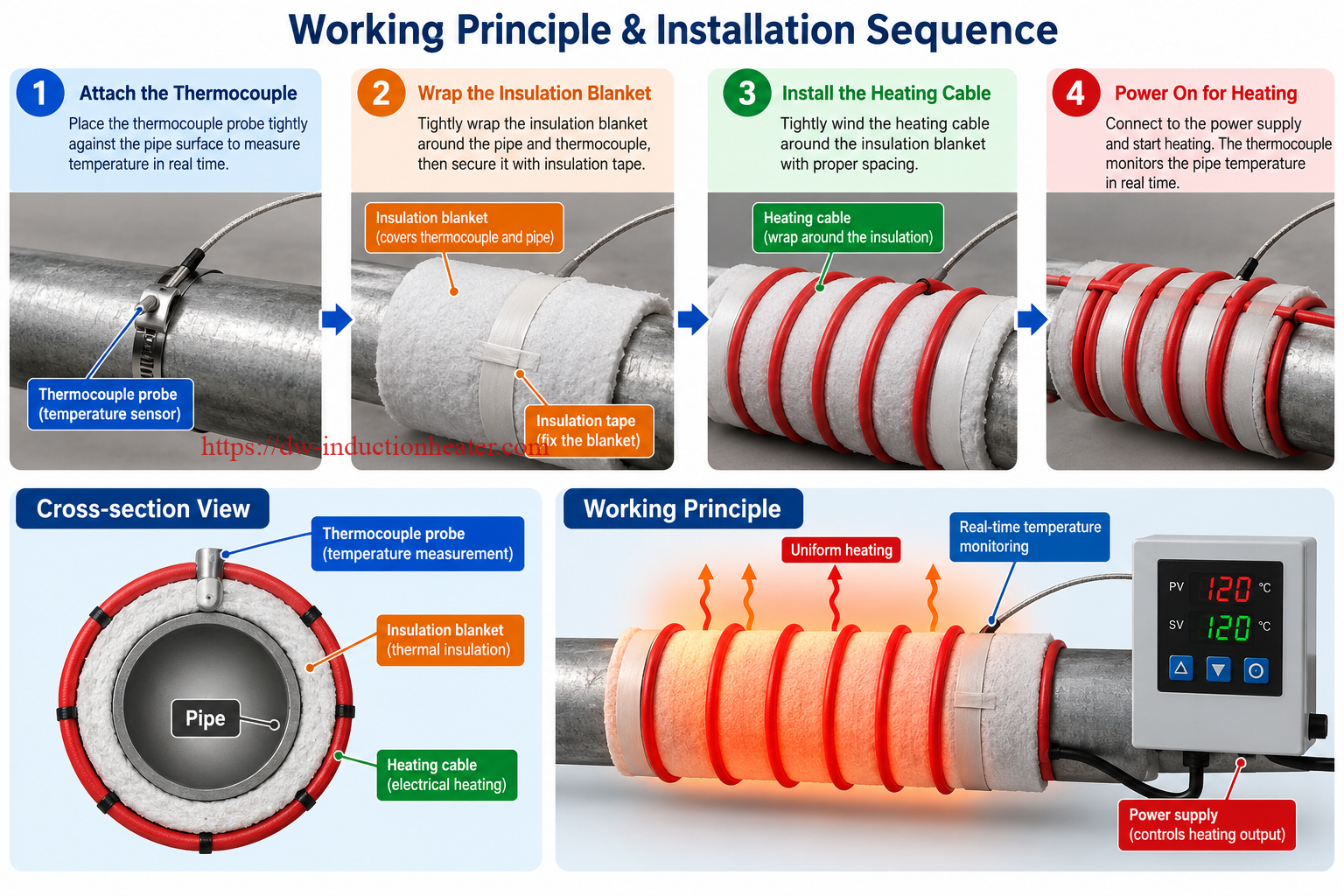
Induction Heating Energy Conversion
| Stage | Process | Result |
|---|---|---|
| 1 | Three-Phase Electrical Supply | Power is supplied to the induction generator |
| 2 | High-Frequency Power Conversion | The generator produces high-frequency electrical output |
| 3 | Induction Coil Energization | An alternating magnetic field develops |
| 4 | Eddy Current Generation | Electrical currents are induced within the steel |
| 5 | Resistance Heating | Electromagnetic energy becomes heat inside the metal |
| 6 | Thermal Conduction | Heat redistributes through the material |
| 7 | Temperature Measurement | Thermocouples or suitable pyrometers monitor the process |
| 8 | Closed-Loop Control | Supported controllers adjust the heating process |
Correct Working Principle for Pipe Welding Preheating
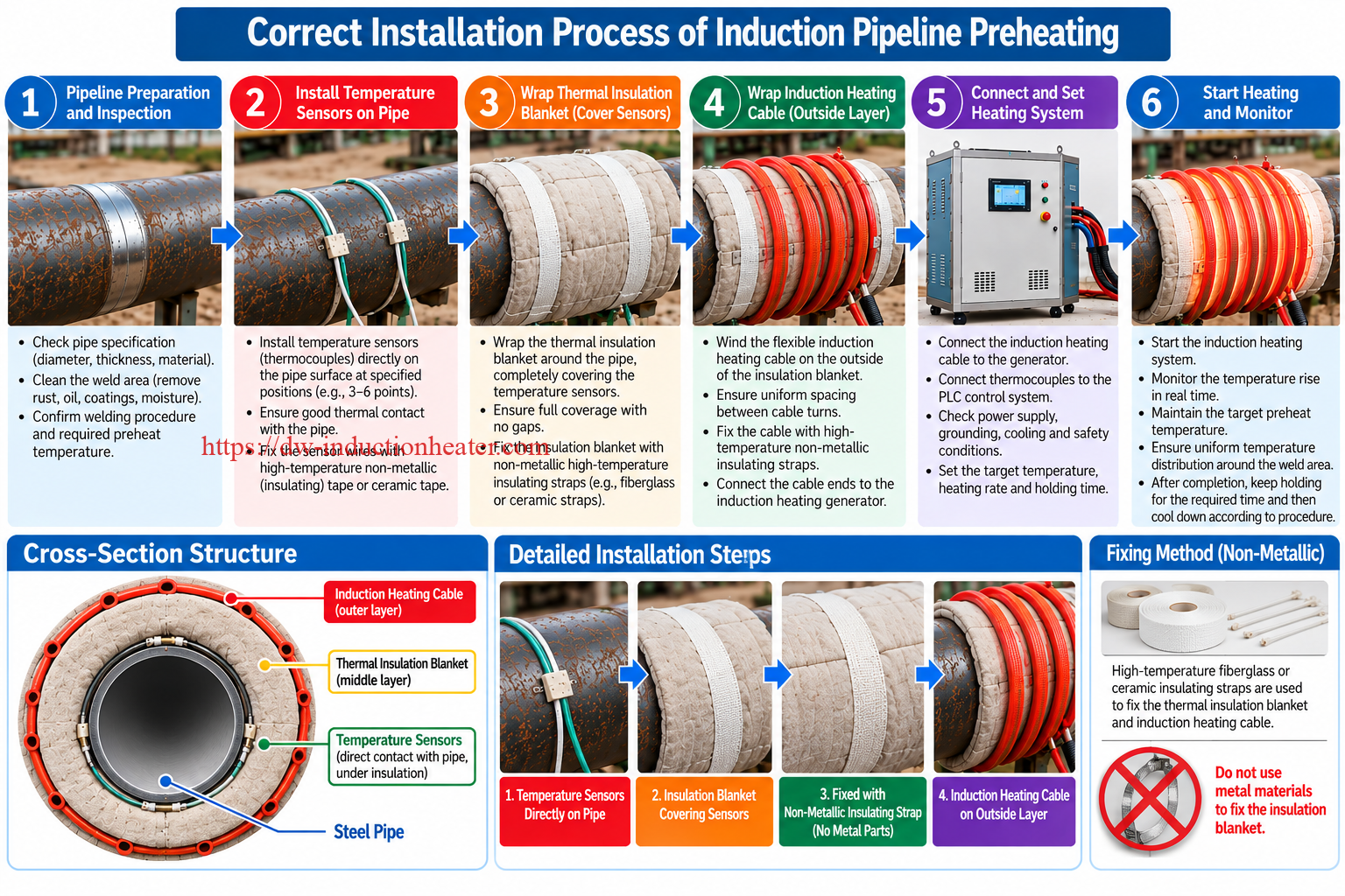
For insulated pipe welding applications, the temperature sensors, insulation, and flexible induction heating cable must be installed in the correct sequence.
Correct installation:
- Clean and inspect the steel pipe surface.
- Install K-type thermocouples directly against the steel pipe at the approved measurement locations.
- Wrap the steel pipe and thermocouples tightly with a suitable thermal insulation blanket.
- Secure the insulation blanket using approved non-metallic, high-temperature insulating fabric straps.
- Wind the flexible induction heating cable around the outside of the thermal insulation blanket.
- Secure the induction cable using appropriate electrically insulating fixing materials.
- Connect the induction heating cable and thermocouples to the designated equipment terminals.
- Verify the electrical installation, temperature readings, cooling requirements, and safety conditions before energizing the system.
Pipe Heating Layer Structure
| Layer | Component | Purpose |
|---|---|---|
| 1 – Workpiece | Steel Pipe | Metal heated through electromagnetic induction |
| 2 – Direct Contact | Thermocouple Junction | Measures actual metal-surface temperature |
| 3 – Middle Layer | Thermal Insulation Blanket | Covers the pipe and temperature sensors while reducing heat loss |
| 4 – Outside Layer | Flexible Induction Heating Cable | Generates the electromagnetic heating field |
| 5 – Securing Method | Non-Metallic Insulating Straps | Fixes the insulation and cable according to the approved installation |
Important: The thermocouple must directly contact the steel pipe. It must not be mounted on top of the insulation blanket.
Unapproved metallic straps, steel wires, and conductive fixing bands should not be used in the active induction-heating region.
For different induction coil structures, see HLQ flexible induction heating cables and related accessories.
Working Principle for Continuous Steel Strip Heating
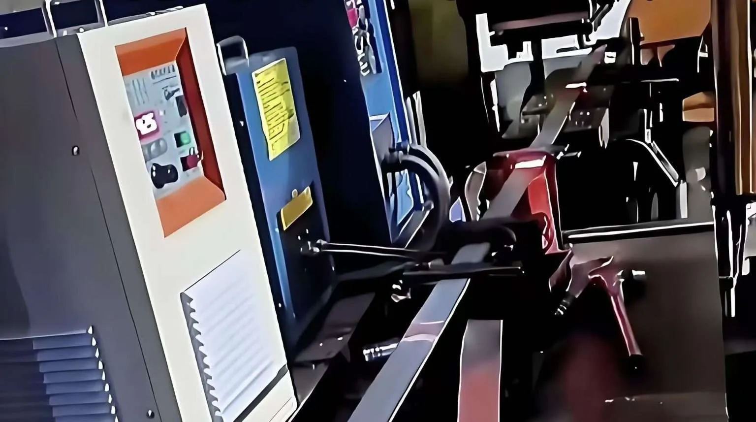
Continuous steel strip heating normally uses a fixed induction coil while the strip moves through the heating zone.
The coil configuration may use longitudinal magnetic flux, transverse magnetic flux, or localized edge heating depending on the strip dimensions and process requirements.
Production-line systems commonly require temperature feedback and power adjustment when line speed or material dimensions change.
Unlike stationary pipe heating, continuously moving strips are generally not wrapped with thermal insulation blankets and flexible heating cables.
Induction Coil Configurations
| Coil Type | Typical Application | Important Design Factor |
|---|---|---|
| Flexible Induction Cable | Stationary pipes and suitable fabricated steel components | Number of turns, spacing, insulation, electrical matching |
| Localized Work Coil | Steel plate or structural weld area | Coil shape and magnetic field distribution |
| Longitudinal-Flux Coil | Selected steel strip geometries | Strip dimensions and through-heating requirements |
| Transverse-Flux Coil | Selected wide-strip heating applications | Cross-width temperature distribution |
| Edge-Heating Coil | Selective heating near steel strip edges | Edge-zone width and line speed |
Technical Specifications
Industrial induction preheating equipment must be selected according to the actual application rather than a single universal specification.
The following MYD model data are based on existing HLQ product information.
HLQ MYD Industrial Welding Preheating Equipment
| Model | Published Nominal Output | Published Frequency | Published Input Current |
|---|---|---|---|
| MYD-40 | 40 kW | 2-36 kHz | 60 A |
| MYD-50 | 50 kW | 2-36 kHz | 75 A |
| MYD-60 | 60 kW | 2-36 kHz | 90 A |
| MYD-80 | 80 kW | 2-36 kHz | 120 A |
| MYD-100 | 100 kW | 2-36 kHz | 150 A |
| MYD-120 | 120 kW | 2-36 kHz | 180 A |
Published-data notice: The original input-current figures require reconciliation with the stated nominal output ratings. Confirm actual rated input current, power factor, conversion efficiency, cooling conditions, and continuous operating duty before electrical installation or purchase.
Published MYD Common System Features
| Item | Manufacturer-Published Information | Engineering Clarification |
|---|---|---|
| Standard Input Supply | Three-phase 380 V | Verify local frequency and electrical load |
| Optional Input Voltage | Three-phase 220 V or 440 V | Confirm availability for the selected model |
| Power Electronics | IGBT | Confirm current production version |
| Control Interface | PLC Touchscreen | Actual functions depend on configuration |
| Temperature Monitoring | Published multi-channel capability | Confirm channel number and measurement accuracy |
| Temperature Recorder | Available for selected configurations | Confirm recording and export functions |
| Cooling | Model-dependent air or liquid-cooling arrangements | Verify generator and coil cooling requirements |
Continuous Steel Strip Heating System Parameters
HLQ also publishes custom induction strip heating solutions covering a broad range of strip dimensions and production requirements.
| Parameter | Website-Published Capability Range | Selection Requirement |
|---|---|---|
| Custom System Power | 15-2,000 kW | Application-specific engineering design |
| Strip Width | 5-2,000 mm | Coil geometry and heated width |
| Strip Thickness | 0.05-25 mm | Penetration, thermal mass, and heating time |
| Frequency Range | 1-500 kHz | Workpiece properties and electromagnetic design |
| Coil Arrangement | Longitudinal, transverse, or edge-focused | Application-specific configuration |
| Line-Speed Control | Custom production-line integration | Synchronization with actual strip speed |
These ranges describe published custom-equipment capabilities rather than a single standardized machine specification.
Recommended Model Selection
The best induction preheating machine depends on the quantity of steel being heated, the temperature rise, the required heating time, and the actual energy absorbed by the workpiece.
Preliminary Model Selection by Application
| Application | Initial Equipment Consideration | Main Verification Requirement |
|---|---|---|
| Localized Structural Steel Preheat | Industrial MYD system with suitable local coil | Heated mass and temperature uniformity |
| Medium Steel Pipe Joint | MYD-40 to MYD-60 as preliminary candidates | Pipe wall, band width, ramp time |
| Large Pipe Weld Heating | MYD-60 to MYD-120 as preliminary candidates | Useful thermal power and cooling |
| Steel Strip-End Butt-Weld Preheat | Custom local induction work coil | Strip dimensions and weld cycle |
| Continuous Steel Strip Preheating | Dedicated inline strip heating system | Mass flow and line-speed control |
| Steel Strip Edge Heating | Specialized edge induction coil | Heated edge width and process integration |
These recommendations are preliminary categories rather than guaranteed power selections.
The actual generator rating must be confirmed through calculations, coil matching, operating-duty assessment, and representative testing.
Model Selection Checklist
| Parameter | Structural Steel | Steel Pipes | Steel Strips |
|---|---|---|---|
| Material Grade | Required | Required | Required |
| Thickness | Plate or section thickness | Wall thickness | Strip gauge |
| Heating Area | Local weld region | Circumferential band | Full width or selected edge |
| Heating Time | Batch ramp time | Joint heating time | Travel time or welding cycle |
| Production Speed | Usually batch-specific | Usually batch-specific | Critical for continuous lines |
| Temperature Measurement | Contact sensors | Contact sensors | Often non-contact measurement |
| Coil Design | Local geometry | Circumferential cable | Inline or edge-focused |
Process Workflow
A. Structural Steel Induction Preheating Workflow
- Identify the steel grade and applicable welding procedure.
- Determine the required preheat temperature and welding-zone dimensions.
- Evaluate the workpiece thickness and approximate heated mass.
- Select a compatible induction generator and local work coil.
- Install temperature sensors at the specified measurement positions.
- Apply suitable insulation where required by the approved heating arrangement.
- Check the electrical system, coil installation, and temperature monitoring.
- Start heating and monitor the temperature response.
- Verify the specified preheat temperature before welding.
- Maintain applicable preheat and interpass requirements during welding.
B. Steel Pipe Induction Preheating Workflow
- Inspect the pipe and confirm the steel grade, OD, wall thickness, and weld location.
- Attach thermocouples directly against the steel surface.
- Cover the pipe and thermocouples with thermal insulation blankets.
- Secure the insulation using non-metallic, high-temperature insulating fabric straps.
- Wind the induction heating cable around the outside of the insulation.
- Secure the heating cable using the approved insulating arrangement.
- Connect the generator, heating cable, and thermocouples.
- Inspect electrical connections, cooling conditions, and temperature readings.
- Energize the induction heating system and monitor the pipe temperature.
- Complete the heating process according to the approved welding procedure.
C. Continuous Steel Strip Preheating Workflow
- Identify strip grade, width, thickness, and required heating region.
- Determine line speed, initial temperature, and target temperature.
- Calculate the continuous mass flow and required thermal power.
- Select the appropriate longitudinal-flux, transverse-flux, or edge-heating coil.
- Install the coil within the production-line arrangement.
- Position and configure suitable temperature-measurement equipment.
- Synchronize induction power control with the strip handling system.
- Verify safety interlocks and the response to a line stop.
- Start the production line and monitor strip temperature.
- Adjust the heating process according to the approved production parameters.

Process Comparison
| Process Element | Structural Steel | Steel Pipes | Steel Strips |
|---|---|---|---|
| Workpiece Movement | Usually stationary | Usually stationary | Stationary ends or continuous movement |
| Coil Installation | Local geometry | Circumferential arrangement | Inline or edge heating |
| Thermal Insulation | Application-dependent | Common for insulated cable heating | Process-dependent, usually not wrapped around moving strip |
| Temperature Measurement | Contact sensors | Direct-contact thermocouples | Often non-contact pyrometers |
| Control Focus | Localized heating uniformity | Circumferential temperature control | Strip speed and exit temperature |
Common Problems and Solutions
Incorrect induction preheating performance can result from unsuitable coil geometry, inadequate useful power, poor temperature measurement, incorrect insulation, or unexpected heat conduction.
Industrial Troubleshooting Table
| Problem | Possible Cause | Recommended Solution |
|---|---|---|
| Slow Heating | Large metal mass or inadequate useful thermal power | Recalculate thermal demand and review coil matching |
| Uneven Structural Steel Temperature | Asymmetric component geometry or coil field | Review coil design and measurement locations |
| Uneven Pipe Circumference Temperature | Irregular cable spacing or uneven heat losses | Check induction cable arrangement and insulation |
| Incorrect Thermocouple Reading | Poor metal contact or sensor mounted on insulation | Reinstall the thermocouple directly against the steel |
| Insulation Fixing Material Overheats | Unapproved conductive metallic fixing material | Stop operation and use suitable non-metallic insulating straps |
| Steel Strip Edge Overheating | Concentrated electromagnetic field or insufficient control | Review edge-coil profile and temperature feedback |
| Strip Temperature Rises After Line Slowdown | Power control not synchronized with line speed | Verify speed feedback and heating interlocks |
| Generator Overheating | Insufficient cooling or excessive operating duty | Check cooling systems and approved output limits |
| Excessive Temperature Overshoot | Control delay or unsuitable heating settings | Review control response and sensor placement |
| Unstable Heating Power | Electrical mismatch or changing coil coupling | Inspect the generator and induction circuit |
Engineering Selection Guide
Engineering selection begins by calculating the thermal energy required by the actual workpiece.
However, structural steel, stationary pipes, and continuously moving steel strips require different mass calculations.
1. Basic Thermal Energy Equation
The approximate sensible heat required to raise a metal mass to a target temperature is:
Q = m × Cp × ΔT
Where:
- Q = required sensible heat, kJ.
- m = heated steel mass, kg.
- Cp = average specific heat capacity, kJ/(kg·K).
- ΔT = target temperature minus initial temperature, K.
For a simplified power estimate:
P useful = Q / Heating Time
Actual electrical generator power must additionally account for coupling, thermal losses, conversion losses, operating duty, and an appropriate engineering margin.
Engineering Example 1: Structural Steel Plate Preheating
Consider a hypothetical structural steel welding operation involving a selected rectangular plate heating zone.
| Engineering Parameter | Value |
|---|---|
| Steel Plate Heating Length | 600 mm |
| Heating Width | 300 mm |
| Plate Thickness | 20 mm |
| Initial Temperature | 20°C |
| Target Temperature | 150°C |
| Temperature Rise | 130 K |
| Assumed Steel Density | 7,850 kg/m³ |
| Assumed Mean Specific Heat | 0.49 kJ/(kg·K) |
| Target Heating Time | 5 minutes |
Step A: Calculate the Heated Steel Mass
m = Length × Width × Thickness × Density
m = 0.60 × 0.30 × 0.020 × 7850
m = 28.26 kg
Step B: Calculate the Sensible Heat
Q = 28.26 × 0.49 × 130
Q ≈ 1,800 kJ = 0.500 kWh
Step C: Calculate the Minimum Average Useful Thermal Power
P useful = 1800 / 300
P useful ≈ 6.00 kW
This is an idealized heating-load estimate. Actual equipment selection must consider additional heated metal, thermal losses, electromagnetic coupling, and heating-zone uniformity.
Engineering Example 2: Steel Pipe Welding Preheating
Consider a carbon steel pipe requiring localized circumferential preheating.
| Engineering Parameter | Value |
|---|---|
| Pipe Outside Diameter | 323.9 mm |
| Pipe Wall Thickness | 12.7 mm |
| Axial Heating Band | 400 mm |
| Initial Temperature | 25°C |
| Target Temperature | 200°C |
| Temperature Rise | 175 K |
| Assumed Steel Density | 7,850 kg/m³ |
| Assumed Mean Specific Heat | 0.49 kJ/(kg·K) |
| Target Heating Time | 5 minutes |
Step A: Calculate the Pipe Mass
m = π × (D – t) × t × L × ρ
m = 3.1416 × (0.3239 – 0.0127) × 0.0127 × 0.400 × 7850
m ≈ 38.99 kg
Step B: Calculate the Sensible Heat
Q = 38.99 × 0.49 × 175
Q ≈ 3,343 kJ = 0.929 kWh
Step C: Calculate the Minimum Average Useful Thermal Power
P useful = 3343 / 300
P useful ≈ 11.14 kW
The result does not include all axial heat conduction, external losses, coil losses, or additional heat required for temperature equalization.
Engineering Example 3: Continuous Steel Strip Preheating
Continuous steel strip heating requires a mass-flow calculation because fresh material enters the heating zone continuously.
Operating Parameters
| Engineering Parameter | Value |
|---|---|
| Strip Width | 800 mm |
| Strip Thickness | 2.0 mm |
| Production Line Speed | 10 m/min |
| Initial Temperature | 20°C |
| Target Temperature | 100°C |
| Temperature Rise | 80 K |
| Assumed Steel Density | 7,850 kg/m³ |
| Assumed Mean Specific Heat | 0.49 kJ/(kg·K) |
Step A: Calculate the Continuous Mass Flow
Mass Flow = Strip Width × Thickness × Line Speed × Density
Line speed = 10 / 60 = 0.1667 m/s
Mass flow = 0.8 × 0.002 × 0.1667 × 7850
Mass flow ≈ 2.093 kg/s
This corresponds to approximately 7.54 tonnes per hour.
Step B: Calculate the Theoretical Thermal Power
P thermal = Mass Flow × Cp × ΔT
P thermal = 2.093 × 0.49 × 80
P thermal ≈ 82.06 kW
Step C: Estimate the Illustrative Installed Power
Assume, for preliminary illustration only, that 70% of the selected electrical input becomes useful heating of the relevant strip material.
Assume a further 20% design allowance.
Estimated installed power = 82.06 / 0.70 × 1.20
Estimated installed power ≈ 140.7 kW
The 70% useful-power fraction and 20% allowance are engineering assumptions, not published measured performance of a particular HLQ generator.
The final rating must be verified using actual equipment efficiency, coil coupling, product requirements, strip temperature distribution, and operating conditions.
Comparison of the Three Engineering Examples
| Application | Calculated Metal Mass or Flow | Temperature Rise | Theoretical Heating Requirement |
|---|---|---|---|
| Structural Steel Plate | 28.26 kg | 130 K | 1,800 kJ total; 6.00 kW useful power for 5 minutes |
| Steel Pipe | 38.99 kg | 175 K | 3,343 kJ total; 11.14 kW useful power for 5 minutes |
| Continuous Steel Strip | 2.093 kg/s | 80 K | 82.06 kW continuous theoretical thermal power |
Engineering interpretation: The strip heating application requires much greater continuous thermal power because the production line continuously introduces additional cold steel into the heating zone.
Why Useful Thermal Power Is Different from Generator Output Power
| Parameter | Meaning |
|---|---|
| Electrical Input Power | Power drawn from the factory electrical supply |
| Generator Output Power | High-frequency electrical power delivered to the induction circuit |
| Useful Thermal Power | Heat absorbed by the relevant steel region |
| Heat Loss | Energy lost to the surroundings or transferred into adjacent material |
| Available Continuous Output | Power the generator can sustain under verified cooling and operating conditions |
Equipment sizing should distinguish all these quantities rather than treating the nameplate rating as identical to the heat absorbed by the workpiece.
Advantages and Limitations
Advantages of Induction Preheating
1. Localized Heating
Induction coils can be configured to heat selected conductive metal regions without requiring the entire structure to be placed inside a furnace.
2. Suitable for Different Steel Components
Appropriate coil configurations can be evaluated for steel pipes, structural components, plates, and specialized strip processing applications.
3. Temperature Monitoring and Control
Industrial induction systems may incorporate thermocouples, infrared pyrometers, PLC controls, and recording equipment.
4. Reduced Dependence on Open Flames
Induction preheating does not require a combustion flame as its primary heating source.
However, electrically energized equipment and hot steel still present important industrial safety hazards.
5. Integration with Industrial Processes
Dedicated induction strip systems can be integrated with suitably engineered continuous manufacturing lines.
6. Potential Process Repeatability
When coil position, material dimensions, power, and temperature control are consistent, induction heating can support repeatable heating procedures.
Important Limitations
| Limitation | Engineering Explanation | Recommended Action |
|---|---|---|
| Material Dependency | Electrical and magnetic properties affect heating performance | Verify the actual material grade |
| Coil Geometry | Incorrect coil shape can produce uneven heating | Use application-specific coil engineering |
| Thermal Losses | Heat flows into adjacent steel and surroundings | Account for losses in equipment sizing |
| Generator Duty Cycle | Nominal output may not equal continuous usable output | Confirm manufacturer-rated operating conditions |
| High-Speed Strip Lines | Continuous material flow can require substantial power | Calculate mass flow and line-speed requirements |
| Temperature Measurement | Incorrect sensor location can misrepresent metal temperature | Use approved sensor placement and calibration |
| Welding Qualification | Heating equipment alone does not qualify a weld | Follow the approved WPS and inspection requirements |
Induction Preheating Versus Other Heating Methods
| Comparison | Induction Heating | Flame Heating | Resistance Heating |
|---|---|---|---|
| Heat Generation | Within conductive metal | External combustion | Electrical resistance elements |
| Open Flame Required | No | Yes | No |
| Localized Heating | Depends on coil arrangement | Depends on burner position | Depends on element placement |
| Temperature Monitoring | Can use thermocouples or pyrometers | Requires suitable measurement equipment | Can use thermocouples |
| Continuous Strip Integration | Possible with dedicated equipment | Process-dependent | Process-dependent |
| Efficiency | Application-dependent | Application-dependent | Application-dependent |
Energy-saving claims should be based on equivalent measured industrial applications rather than fixed percentages applied to every heating process.
Why Choose HLQ?
HLQ Induction Equipment Co., Ltd. supplies industrial induction heating equipment for metal processing, welding preparation, steel pipe heating, selected heat-treatment processes, and custom production-line applications.
Industrial Induction Heating Equipment
HLQ publishes MYD industrial induction heating systems with nominal output ratings from 40 kW to 120 kW for suitable industrial heating applications.
Application-Specific Heating Solutions
Different induction coil arrangements can be evaluated for structural steel, pipe weld joints, and steel strip processing.
Flexible Induction Heating Accessories
Flexible heating cables support selected stationary steel pipe and fabricated metal heating applications.
Custom Strip Heating Technology
HLQ’s published strip heating portfolio includes equipment concepts using longitudinal-flux, transverse-flux, and edge-heating coil arrangements.
Engineering-Based Model Selection
Equipment selection can be based on material dimensions, required temperature rise, production time, continuous mass flow, and available electrical power.
Industrial Temperature Monitoring
Suitable induction heating configurations may incorporate thermocouples, temperature controllers, infrared pyrometers, and process recording systems.
For applications requiring a qualified post-weld thermal cycle, compare HLQ post-weld heat treatment equipment and its process-control requirements.
8 Core FAQs
1. What Is Induction Preheating for Welding?
Induction preheating for welding uses a changing electromagnetic field to generate heat directly inside conductive metal before welding. It is used to establish the temperature required by an approved welding procedure for suitable structural steel, pipes, and other metal components.
2. Why Is Structural Steel Preheated Before Welding?
Structural steel may require preheating to control cooling conditions and reduce the risk of hydrogen-assisted cracking in susceptible steels. The required temperature depends on steel grade, thickness, hydrogen control, restraint, and the applicable welding procedure.
3. Can Induction Heating Be Used for Steel Pipe Welding Preheat?
Yes. Suitable steel pipe joints can be heated using an approved flexible induction cable arrangement. Thermocouples must contact the steel directly, while thermal insulation covers the sensors and pipe. The induction cable is installed outside the insulation blanket.
4. Can Induction Preheating Be Used for Steel Strip Welding?
Yes, for suitable strip-end welding, selective edge heating, and related applications. However, continuously moving strips normally require specialized inline or edge-heating coils rather than a pipe-style flexible cable installation.
5. How Much Induction Power Is Required for Welding Preheating?
Required power depends on heated metal mass or continuous strip mass flow, specific heat capacity, temperature rise, target heating time, and losses. A reliable power recommendation requires these application parameters and verification of equipment capability.
6. What Temperature Is Required for Welding Preheating?
There is no universal temperature suitable for every steel. The correct minimum preheat temperature must be established from the applicable WPS, steel grade, thickness, welding process, and relevant standards.
7. What Is the Difference Between Induction Preheating and PWHT?
Preheating is performed before welding to establish a specified temperature. Formal post-weld heat treatment is performed after welding using a defined thermal cycle that may include controlled heating rates, holding temperatures, soaking periods, cooling rates, and temperature records.
8. What Induction Heating System Is Suitable for Structural Steel, Pipes, and Steel Strips?
Structural steel generally requires a localized coil arrangement, steel pipes can use suitable circumferential induction cables, and continuous steel strips typically require dedicated longitudinal-flux, transverse-flux, or edge-heating equipment. Final selection depends on material dimensions, temperature, heating time, line speed, coil matching, and verified generator performance.