
Induction vs Furnace Quenching and Tempering
Quick Answer
Induction and furnace quenching and tempering both austenitize, quench and temper steel; the difference is how the heat is applied and how parts move through the process. Induction generates heat inside each part and treats bars, shafts and tubes one after another. HLQ data shows tempering in seconds to minutes and a Ø 20 mm bar heated to about 816 °C in 9.90 s. A furnace heats batch loads, and steel data sheets for 42CrMo4 call for holds of at least 30 min for austenitizing and 60 min for tempering. Choose induction for long parts with a repeated cross-section, and a furnace for heavy, mixed or atmosphere-sensitive loads.
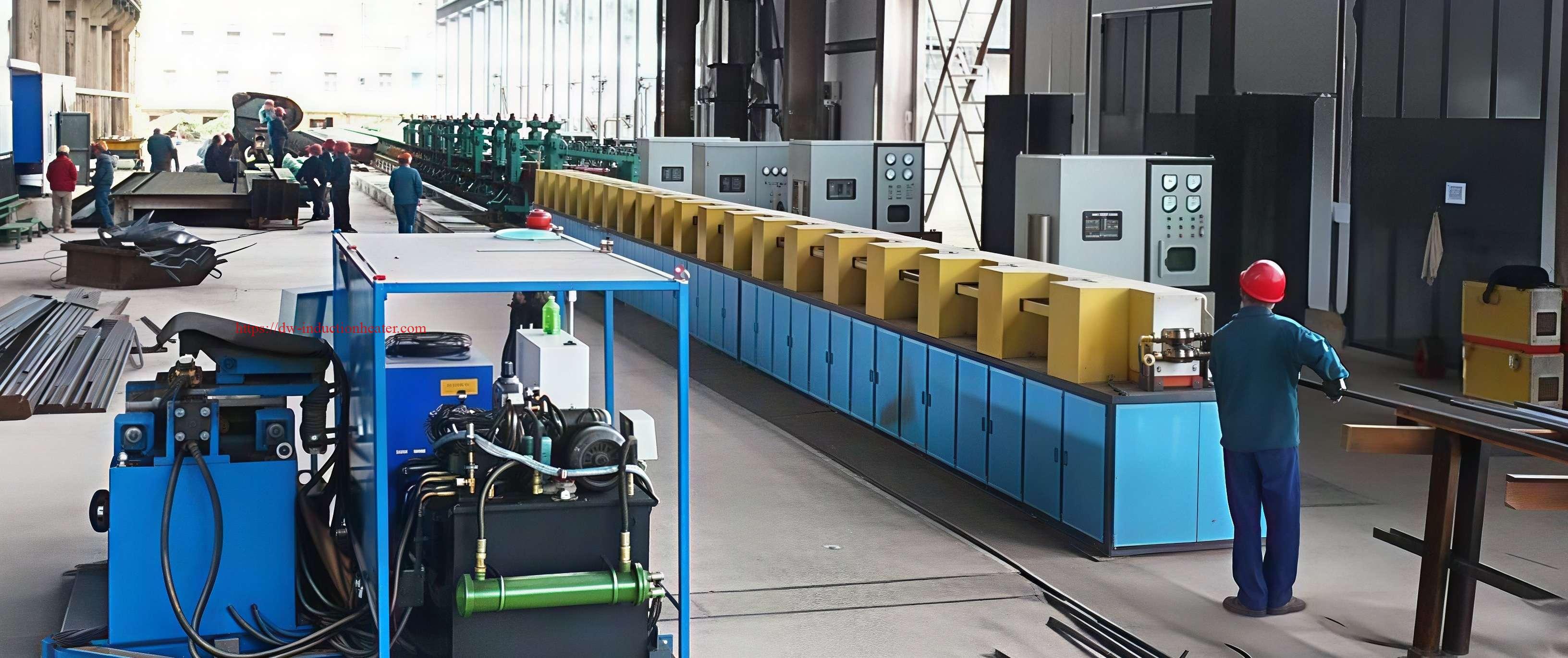
Table of Contents
- What Is Induction vs Furnace Quenching and Tempering?
- Key Applications
- Suitable Materials
- Working Principle
- Technical Specifications
- Recommended Model Selection
- Process Workflow
- Common Problems and Solutions
- Engineering Selection Guide
- Advantages and Limitations
- Why Choose HLQ?
- 8 Core FAQs
What Is Induction vs Furnace Quenching and Tempering?
Quenching and tempering (Q&T) heats steel above its upper critical temperature, quenches it to form martensite, and reheats it below Ac1 to set the final hardness and toughness (see induction hardening and tempering). The process can be done in two ways:
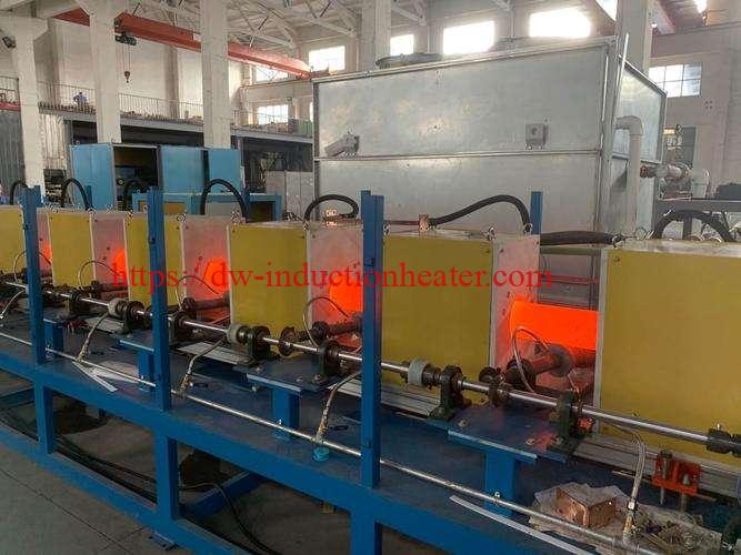
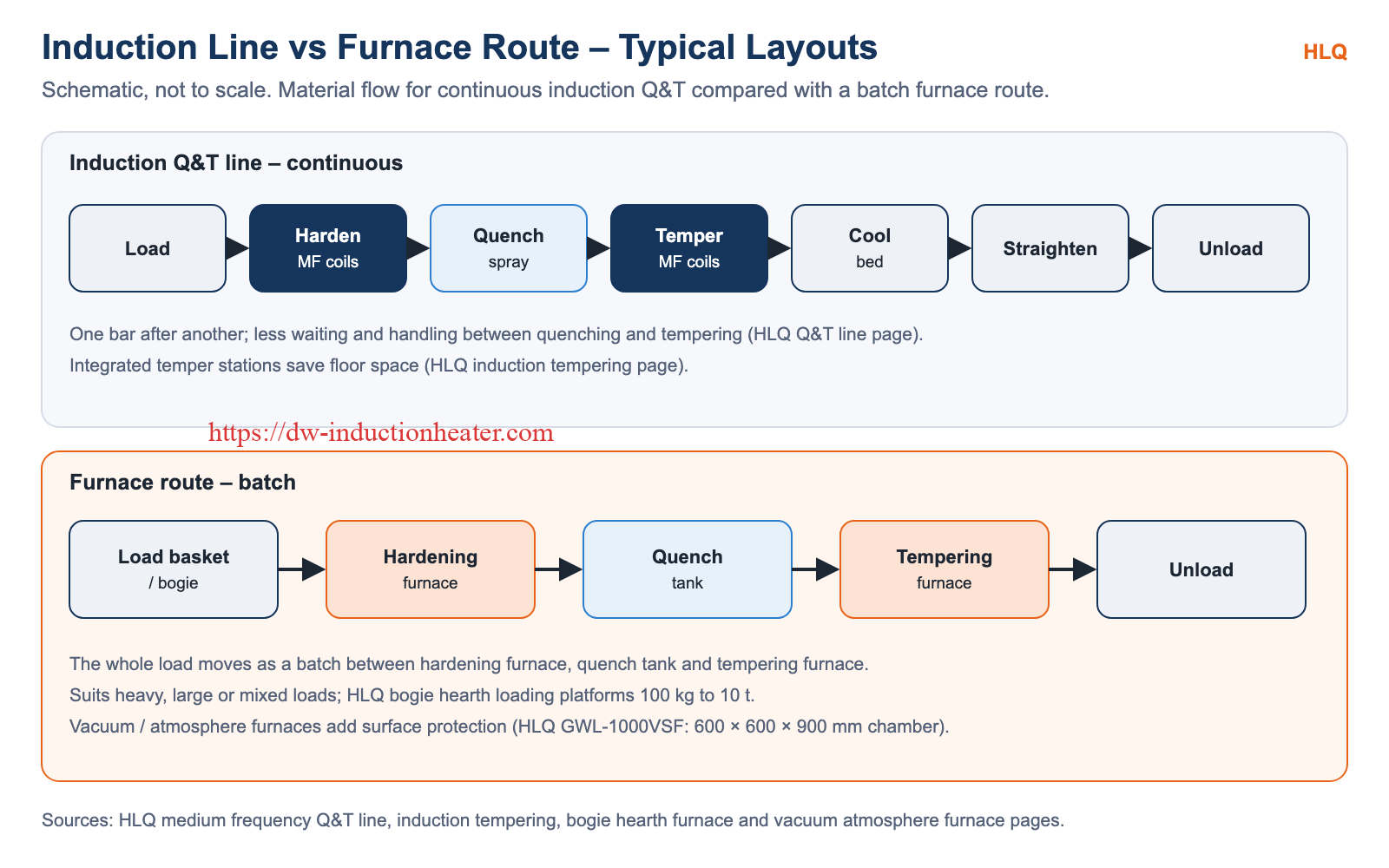
- Induction Q&T: medium frequency coils heat each bar, shaft or tube in a continuous line, followed by a spray quench and induction tempering. The equipment is a medium frequency induction quenching and tempering production line.
- Furnace Q&T: a load of parts is heated in a hardening furnace, quenched in a tank and tempered in a tempering furnace, batch by batch.
HLQ supplies both routes, so this comparison is based on the process rather than on one product.
Key Applications
| Application | Better fit | Reason |
|---|---|---|
| Long bars, shafts and tubes with a repeated cross-section | Induction Q&T line | Continuous, inline, Ø 15–150 mm on HLQ MF-Q&T lines |
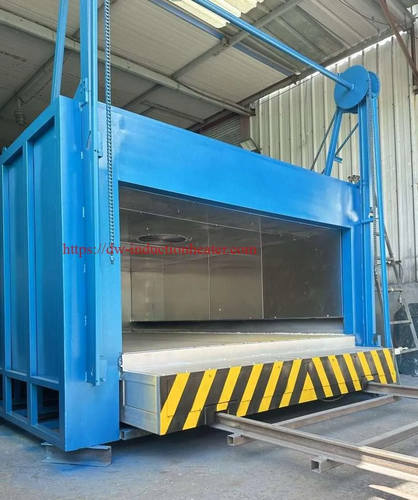
| Heavy, large or odd-shaped parts | Furnace (e.g. bogie hearth) | Batch loads; HLQ bogie hearth loading platforms from 100 kg to 10 t |
| Mixed part sizes in small batches | Furnace | Flexible chamber loading without coil changes |
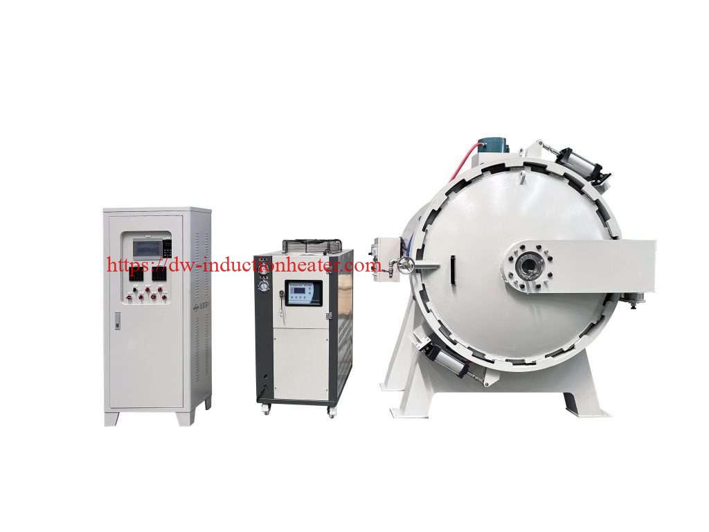
| Parts needing vacuum or protective atmosphere | Vacuum / atmosphere furnace | Controlled environment, e.g. HLQ GWL-1000VSF |
| High-volume lines with per-piece quality control | Induction Q&T line | Each workpiece is treated and recorded individually |
| Fast inline hardening with flexible tempering | Hybrid | Induction hardening and quench, then a continuous tempering furnace |
Suitable Materials
Both routes treat the same Q&T steels; what changes is how the parts are heated and how long they are held. Typical HLQ induction line data:
| Grade | Quenching (°C) | Tempering (°C) | Quench medium | Target (HRC) |
|---|---|---|---|---|
| 45# steel | 840–860 | 550–600 | Water / polymer | 28–34 |
| 40Cr | 840–870 | 520–600 | Oil / polymer | 30–38 |
| 42CrMo | 840–880 | 540–620 | Oil / polymer | 32–40 |
| 35CrMo | 840–870 | 500–580 | Oil / polymer | 30–36 |
For furnace practice, a 42CrMo4 data sheet citing EN 10083 gives austenitizing at 820–860 °C for at least 30 minutes and tempering at 540–680 °C for at least 60 minutes.
Working Principle
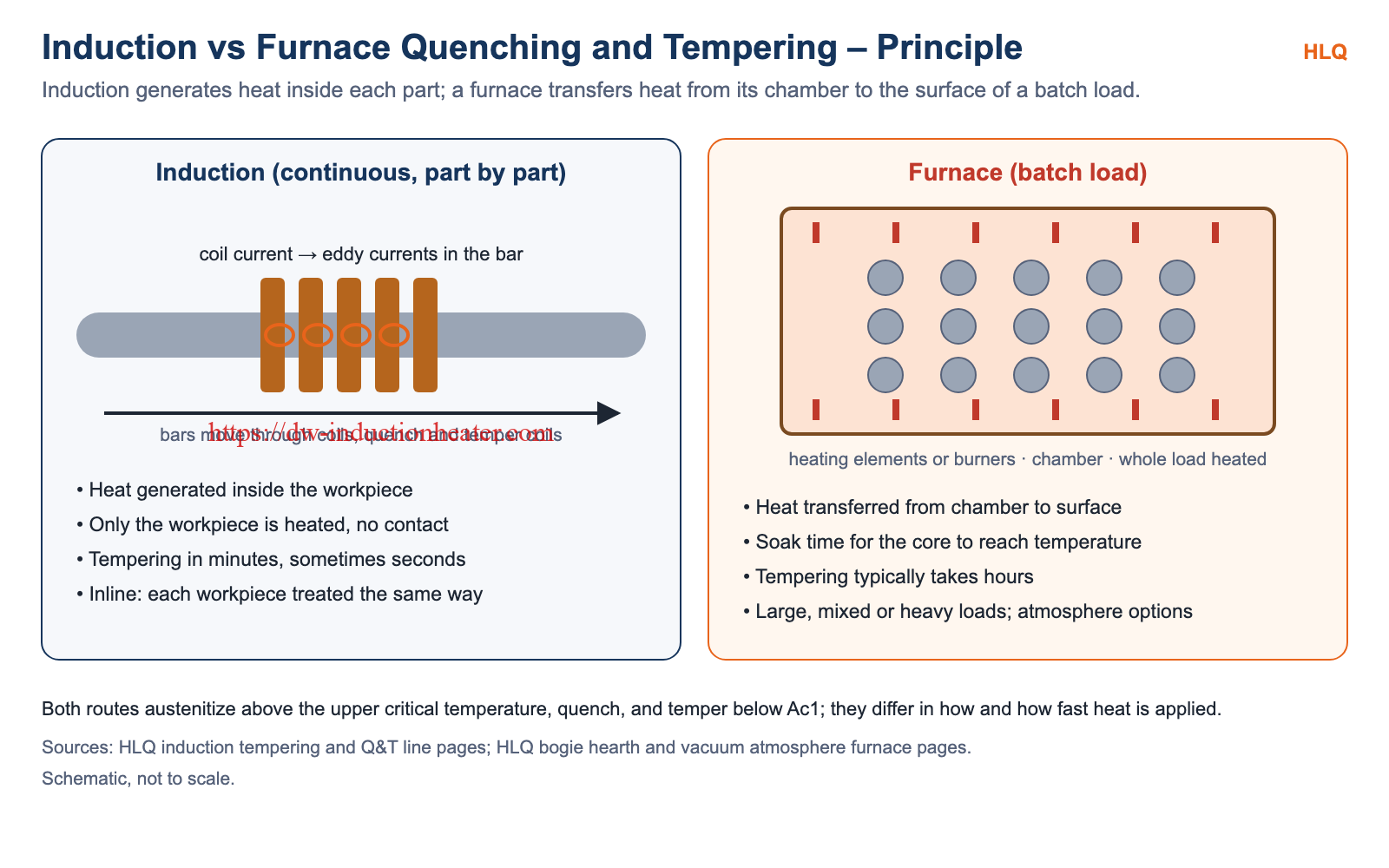
Induction: alternating current in the coil induces eddy currents inside the steel, so the heat is generated in the workpiece itself and only the workpiece is heated, with no contact. Medium frequency (1–20 kHz) reaches deep into the bar, so the core is heated as thoroughly as the surface. Induction tempering takes minutes, sometimes seconds.
Furnace: heating elements or burners heat the chamber, and the heat passes to the surface of the load and then by conduction to its core. The load must therefore soak at temperature, and tempering in a furnace typically takes hours.
Technical Specifications
| Item | Induction Q&T | Furnace Q&T |
|---|---|---|
| Heat source | Heat generated inside the workpiece by eddy currents | Heat transferred from elements or burners to the load surface |
| Processing | Continuous, part by part, inline | Batch loads |
| Tempering time | Minutes, sometimes seconds | Typically hours; 42CrMo4 data sheet hold ≥ 60 min |
| What is heated | Only the workpiece | Chamber, fixtures and the whole load |
| Quality control | Individual workpieces; PLC recipes per diameter and grade | Per batch |
| Handling between stages | Less waiting and handling between quenching and tempering | Load moved between furnace, quench tank and tempering furnace |
| Part range | Bars, shafts, tubes Ø 15–150 mm (HLQ MF-Q&T lines) | Heavy, large or mixed parts (HLQ bogie loads 100 kg–10 t) |
| Atmosphere | Open-air line | Vacuum / atmosphere furnaces available |
| Safety standards | IEC 60519 series for electroheating installations | NFPA 86 for ovens and furnaces (fuel-fired) |
| Data point | Time | Source |
|---|---|---|
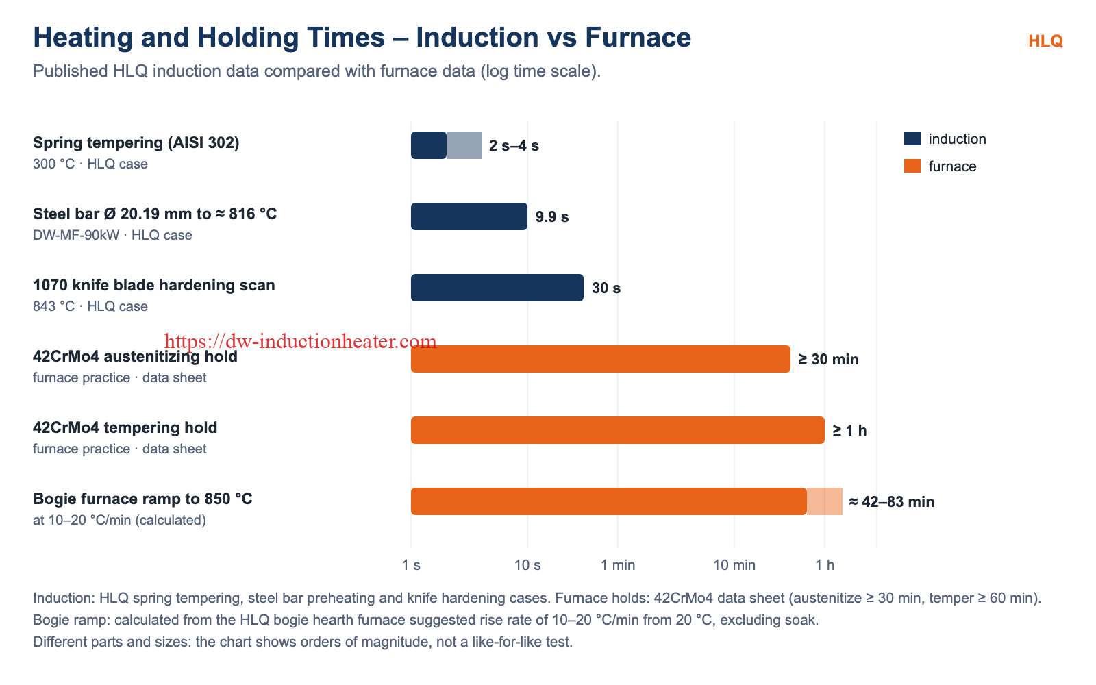
| AISI 302 springs tempered to 300 °C (induction) | 2–4 s | HLQ spring tempering case |
| Ø 20.19 mm steel bar heated to about 816 °C (induction, preheating) | 9.90 s | HLQ steel bar preheating case |
| 1070 knife blade hardening scan to 843 °C (induction) | 30 s | HLQ knife blade case |
| 42CrMo4 austenitizing hold (furnace) | ≥ 30 min | Steel data sheet (EN 10083) |
| 42CrMo4 tempering hold (furnace) | ≥ 60 min | Steel data sheet (EN 10083) |
| Bogie furnace ramp from 20 °C to 850 °C | ≈ 42–83 min | Calculated from the HLQ suggested rise rate of 10–20 °C/min, excluding soak |
The parts and sizes differ, so these figures show orders of magnitude rather than a like-for-like test.
Recommended Model Selection
Induction Q&T lines (typical HLQ values):
| Model | Power | Frequency | Bar diameter | Output |
|---|---|---|---|---|
| MF-Q&T-150 | 150 kW | 8–15 kHz | Ø 15–40 mm | 0.3–0.8 t/h |
| MF-Q&T-300 | 300 kW | 5–10 kHz | Ø 20–60 mm | 0.6–1.5 t/h |
| MF-Q&T-500 | 500 kW | 3–8 kHz | Ø 30–80 mm | 1.0–2.5 t/h |
| MF-Q&T-800 | 800 kW | 3–5 kHz | Ø 40–120 mm | 2.0–4.0 t/h |
| MF-Q&T-1000 | 1000 kW | 2–4 kHz | Ø 50–150 mm | 3.0–5.0 t/h |
HLQ heat treatment furnaces:
| Furnace | Key data (HLQ) |
|---|---|
| Electric bogie hearth furnace GWL-STCS | Working temperature 1200–1800 °C depending on version; loading platform 100 kg to 10 t; suggested temperature rise 10–20 °C/min; temperature control accuracy ±1 °C; 220 V / 380 V |
| Vacuum atmosphere heat treatment furnace GWL-1000VSF | 1000 °C; chamber 600 × 600 × 900 mm (D × W × H); 45 kW; heating rate up to 15 °C/min; temperature uniformity ±5 °C; K-type thermocouple |
Process Workflow
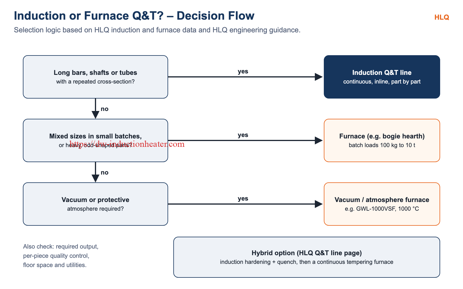
- Part shape: long bars, shafts or tubes with a repeated cross-section point to an induction Q&T line.
- Batch and size mix: mixed sizes in small batches, or heavy and odd-shaped parts, point to a furnace.
- Atmosphere: if vacuum or a protective atmosphere is required, use a vacuum / atmosphere furnace.
- Hybrid: an induction line can harden and quench, then feed a continuous tempering furnace.
- Final check: output, per-piece quality control, floor space and utilities.
Common Problems and Solutions
| Problem | Route | Solution |
|---|---|---|
| Long cycle times and waiting between stages | Furnace | Move long parts of constant section to an inline induction line |
| Frequent size changes | Induction | PLC recipes and quick-change coils, or a furnace for very mixed batches |
| Heavy or odd-shaped parts that cannot pass through a coil | Induction | Use a bogie hearth furnace |
| Surface protection needed | Open-air induction | Use a vacuum / atmosphere furnace |
| Batch-to-batch variation and no per-piece records | Furnace | Induction line with per-workpiece control and data logging |
| Bent long bars after treatment | Both | Skew-roller rotation in the induction line and a straightener after cooling |
Engineering Selection Guide
- Geometry: constant-section bars and tubes suit induction; complex or bulky parts suit furnaces.
- Volume: continuous, high-volume production favours induction; small, mixed batches favour furnaces.
- Atmosphere: vacuum or protective atmosphere requires a suitable furnace.
- Quality records: per-piece control and data logging come built in with induction lines.
- Floor space: integrated induction temper stations save floor space.
- Safety design: electroheating installations follow the IEC 60519 series; fuel-fired furnaces follow NFPA 86. See also induction heating vs gas furnace for forging.
Advantages and Limitations
| Route | Advantages | Limitations |
|---|---|---|
| Induction | Seconds to minutes per heating stage; only the workpiece is heated; inline per-piece control; saves floor space | Best for constant cross-sections; coils change with size; open-air line |
| Furnace | Heavy, large and mixed loads; vacuum or atmosphere options; flexible chamber loading | Soak times of 30–60 min and more; batch handling between stages; whole load and chamber heated |
Why Choose HLQ?
- HLQ supplies induction Q&T lines and heat treatment furnaces, so the recommendation follows the process.
- MF-Q&T lines from 150 to 1000 kW for Ø 15–150 mm bars.
- Bogie hearth furnaces for loads from 100 kg to 10 t, and vacuum atmosphere furnaces.
- Hybrid lines combining induction hardening with a continuous tempering furnace.
8 Core FAQs
1. Is induction quenching and tempering faster than furnace treatment?
Yes. HLQ induction tempering takes minutes, sometimes seconds, while furnace data sheets for 42CrMo4 call for holds of at least 30 min for austenitizing and 60 min for tempering.
2. Which parts suit induction Q&T best?
Long bars, shafts and tubes with a repeated cross-section, Ø 15–150 mm on HLQ MF-Q&T lines.
3. Which parts suit furnace Q&T best?
Heavy, large, odd-shaped or mixed parts in batches; HLQ bogie hearth furnaces take loads from 100 kg to 10 t.
4. Can induction and furnace be combined?
Yes. An induction line can harden and quench, then temper in a continuous tempering furnace.
5. Which route gives better quality control?
Induction treats and records each workpiece individually; a furnace is controlled per batch.
6. When is a vacuum or atmosphere furnace needed?
When the part surface must be protected by vacuum or a controlled atmosphere during heat treatment.
7. Do both routes reach the same hardness?
Both follow the same metallurgy: austenitize, quench, temper below Ac1. The hardness depends on grade, quench and tempering temperature, e.g. 32–40 HRC for 42CrMo on HLQ lines.
8. Which safety standards apply?
Electroheating installations follow the IEC 60519 series; ovens and fuel-fired furnaces follow NFPA 86, plus local codes.