
To select an induction quench and temper line, start from the workpiece range (diameter, length, weight, steel grade), the required throughput in tons per hour and the hardness and property targets. Then choose the frequency, power, quench system, tempering method and layout. For through heating, HLQ recommends 2–8 kHz for 20–50 mm bars and 0.5–2 kHz for billets over 50 mm. HLQ MF-Q&T lines run from 150 to 1000 kW and cover Ø 15–150 mm at 0.3–5.0 t/h.
Table of Contents
- What Is an Induction Quench and Temper Line?
- Key Applications
- Suitable Materials
- Working Principle
- Technical Specifications
- Recommended Model Selection
- Process Workflow
- Common Problems and Solutions
- Engineering Selection Guide
- Advantages and Limitations
- Why Choose HLQ?
- 10 Core FAQs
What Is an Induction Quench and Temper Line?
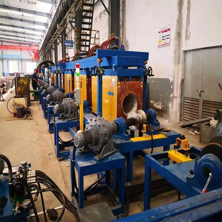
An induction quench and temper (Q&T) line is a continuous, automatic heat-treatment line for bars, shafts and tubes. It heats the steel with medium frequency induction to the austenitizing temperature, quenches it, and then tempers it. Because the whole cross-section is treated, the part gets uniform mechanical properties for heavy loads, impact and fatigue. For the metallurgy and temperatures, see induction hardening and tempering.
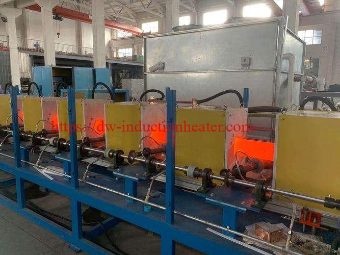
A typical line includes the following systems:
- Loading and feeding
- Medium frequency power supplies and induction coils
- A quenching system
- A tempering system
- Cooling, straightening and unloading
- PLC control and monitoring
The equipment page for these lines is the medium frequency induction quenching and tempering production line.
Key Applications
| Industry | Typical workpieces |
|---|---|
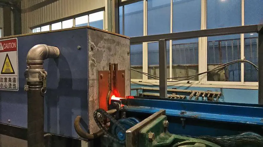
| Automotive and commercial vehicles | Drive shafts, axle shafts, torsion bars, stabilizer bars, gear shafts, steering and suspension parts |
| Construction machinery and agriculture | Pins, bushings, bucket rods, track links, hydraulic cylinder rods, tie rods, structural bars |
| Oil, gas and mining | Drill rods, drill pipes, sucker rods, casing, tubing and coupling sleeves |
| Metallurgy and general engineering | Roller shafts, mandrels, transmission shafts, high-strength bolts, spindles |
For tubes and pipes, see induction pipe and tube heating. For single shafts and pins, see the induction shaft hardening machine.
Suitable Materials
The steel grade sets the quench temperature, quenchant and tempering temperature, and these in turn affect line length and power. HLQ typical process data:
| Material | Quenching (°C) | Tempering (°C) | Cooling medium | Target hardness (HRC) | Typical application |
|---|---|---|---|---|---|
| 45# steel | 840–860 | 550–600 | Water / polymer | 28–34 | General shafts, rods, pins |
| 40Cr | 840–870 | 520–600 | Oil / polymer | 30–38 | Axle shafts, gear shafts, high-strength bolts |
| 42CrMo | 840–880 | 540–620 | Oil / polymer | 32–40 | Heavy-duty shafts, drill rods |
| 35CrMo | 840–870 | 500–580 | Oil / polymer | 30–36 | Connecting rods, high-load parts |
| Alloy tube | 850–900 | 550–650 | Water / polymer | 28–36 | Mechanical tubes, hydraulic cylinders |
Steel data sheets citing EN 10083 give the following ranges:
- C45: 820–860 °C hardening, 550–660 °C tempering.
- 42CrMo4: 820–860 °C hardening, 540–680 °C tempering.
- 34CrNiMo6: 830–860 °C (oil) hardening, 540–660 °C tempering.
Working Principle
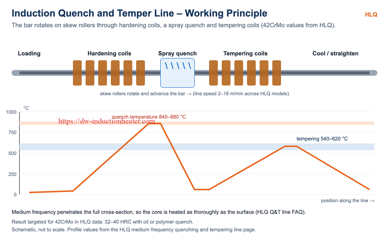
Medium frequency current (1–20 kHz) in the hardening coils induces eddy currents inside the steel and heats it quickly and evenly to the austenitizing temperature. Medium frequency reaches deep into the bar, so the core is heated as thoroughly as the surface. A spray ring or laminar flow station then quenches the bar, and medium or low frequency tempering coils reheat it to the tempering temperature.
Skew rollers rotate the bar all the way through, so every side of the circumference receives the same heat and the same quench spray. For how frequency sets heating depth, see skin effect in induction heating.
Technical Specifications
Typical HLQ line configurations (all values are examples; the actual design is customized for the product mix and output):
| Model | Power (kW) | Frequency (kHz) | Workpiece diameter (mm) | Workpiece length (m) | Line speed (m/min) | Productivity (t/h) |
|---|---|---|---|---|---|---|
| MF-Q&T-150 | 150 | 8–15 | Ø 15–40 | 2–6 | 2–8 | 0.3–0.8 |
| MF-Q&T-300 | 300 | 5–10 | Ø 20–60 | 3–8 | 2–10 | 0.6–1.5 |
| MF-Q&T-500 | 500 | 3–8 | Ø 30–80 | 4–10 | 3–12 | 1.0–2.5 |
| MF-Q&T-800 | 800 | 3–5 | Ø 40–120 | 4–12 | 3–15 | 2.0–4.0 |
| MF-Q&T-1000 | 1000 | 2–4 | Ø 50–150 | 5–14 | 3–18 | 3.0–5.0 |
HLQ frequency guidance for through heating of steel:
| Item | HLQ guidance |
|---|---|
| Bars 20–50 mm | 2–8 kHz |
| Billets over 50 mm | 0.5–2 kHz |
| Skin depth, hot carbon steel above Curie (ρ ≈ 110 µΩ·cm, μr = 1) | ≈ 16.6 mm at 1 kHz; 5.25 mm at 10 kHz |
| Temperature at which to evaluate skin depth | Process temperature (800–900 °C for steel hardening), not room temperature |

Recommended Model Selection
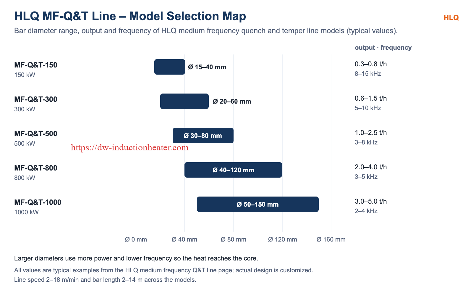
Match the model to the diameter range first, then check the output:
- Ø 15–40 mm, up to 0.8 t/h: MF-Q&T-150 (150 kW, 8–15 kHz).
- Ø 20–60 mm, up to 1.5 t/h: MF-Q&T-300 (300 kW, 5–10 kHz).
- Ø 30–80 mm, up to 2.5 t/h: MF-Q&T-500 (500 kW, 3–8 kHz).
- Ø 40–120 mm, up to 4.0 t/h: MF-Q&T-800 (800 kW, 3–5 kHz).
- Ø 50–150 mm, up to 5.0 t/h: MF-Q&T-1000 (1000 kW, 2–4 kHz).
Power supplies for custom lines include the MFS medium frequency heating systems (3-phase 380 V 50 Hz, 100% duty cycle):
| Model | Rated power | Frequency | Input current | Cooling water flow |
|---|---|---|---|---|
| MFS-100 | 100 kW | 0.5–10 kHz | 160 A | 10–20 m³/h |
| MFS-160 | 160 kW | 0.5–10 kHz | 250 A | 10–20 m³/h |
| MFS-200 | 200 kW | 0.5–10 kHz | 310 A | 10–20 m³/h |
| MFS-250 | 250 kW | 0.5–10 kHz | 380 A | 10–20 m³/h |
| MFS-300 | 300 kW | 0.5–8 kHz | 460 A | 25–35 m³/h |
| MFS-400 | 400 kW | 0.5–8 kHz | 610 A | 25–35 m³/h |
| MFS-500 | 500 kW | 0.5–8 kHz | 760 A | 25–35 m³/h |
| MFS-600 | 600 kW | 0.5–8 kHz | 920 A | 25–35 m³/h |
| MFS-750 | 750 kW | 0.5–6 kHz | 1150 A | 50–60 m³/h |
| MFS-800 | 800 kW | 0.5–6 kHz | 1300 A | 50–60 m³/h |
Process Workflow
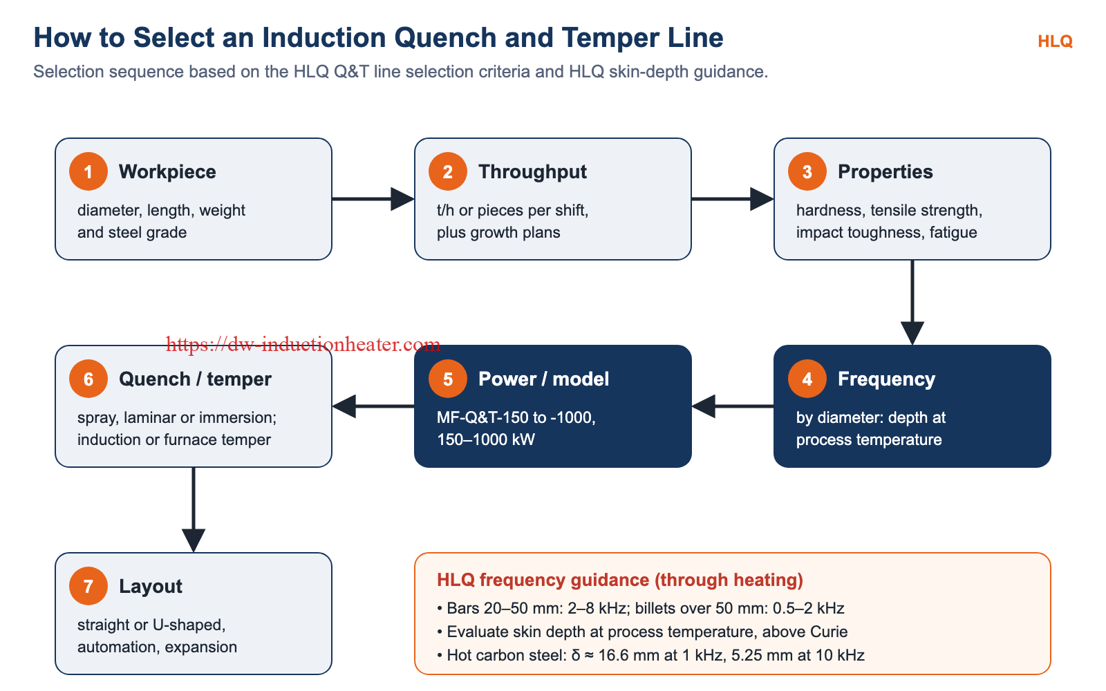
- Workpiece: define the minimum and maximum diameter, length, weight and steel grade.
- Throughput: state tons per hour or pieces per shift, including growth plans.
- Properties: set the hardness range, tensile strength, impact toughness and fatigue life.
- Frequency: choose by diameter, with the skin depth evaluated at process temperature.
- Power and model: select from MF-Q&T-150 to MF-Q&T-1000 (150–1000 kW).
- Quench and temper systems: choose spray ring, laminar flow or immersion quenching, and induction tempering stations or a continuous tempering furnace.
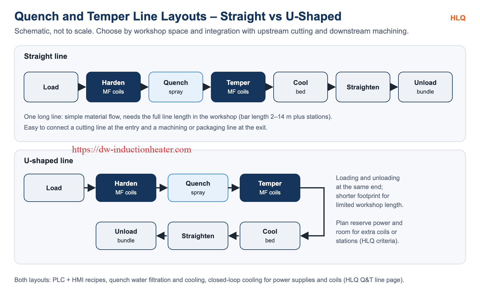
- Layout: choose a straight or U-shaped line, the automation level and the expansion reserve.
Common Problems and Solutions
| Problem | Cause | Solution (HLQ data) |
|---|---|---|
| Core not heated through | Frequency too high for the diameter | Medium frequency by diameter: 2–8 kHz for 20–50 mm, 0.5–2 kHz over 50 mm |
| Low efficiency after a size change | Coil too large for the new diameter | Quick-change coil assemblies for significant diameter changes |
| Bending or warping of long bars | Uneven heating or quenching | Skew rollers rotate the bar; straightening units after cooling |
| Inaccurate temperature control | Smoke or steam on pyrometer lenses | Clean and calibrate pyrometers regularly |
| Arcing in the coils | Oxide scale buildup inside the coils | Regular coil cleaning |
| Blocked power supply or coil cooling | Unclean cooling water | Closed-loop system with clean, distilled water |
| Line too small after a few years | No expansion reserve | Plan reserve power and room for extra coils or stations |
Engineering Selection Guide
- Diameter range: fixes the model and frequency band; a wide range may need several coil sets.
- Output: line speed and power must give the required t/h for the heaviest section.
- Steel grade: sets the quenchant (water/polymer for 45#, oil/polymer for 40Cr, 42CrMo and 35CrMo) and the tempering temperature.
- Utilities: check the supply capacity and cooling water flow. For example, the MFS-500 needs 760 A input current and 25–35 m³/h of water.
- Layout: use a straight line for direct connection to cutting and machining, or a U-shaped line when the workshop is short.
- Control: PLC + HMI recipes per diameter and grade, real-time monitoring and data logging for traceability.
- Data to send: diameter, length and weight range, steel grades, property targets, t/h, power supply, cooling water and floor space.
Advantages and Limitations
| Advantages | Limitations |
|---|---|
| Continuous operation with adjustable line speed | Coils must be changed for significant diameter changes |
| Uniform hardness and microstructure along the full length | Large lines need high supply current and cooling water flow |
| Less waiting and handling between quenching and tempering | Pyrometers and coils need regular cleaning |
| Recipes for different diameters, lengths and grades | The cooling circuit needs clean, distilled water |
| No combustion gases in the workshop | The line must be sized for the largest section and the highest output |
Why Choose HLQ?
- Five standard line sizes, MF-Q&T-150 to MF-Q&T-1000, for Ø 15–150 mm.
- MFS medium frequency power supplies from 100 to 800 kW, 0.5–10 kHz.
- Quick-change coils and PLC recipes for fast product changeover.
- Straight or U-shaped layouts, with integration into cutting, machining and packaging lines.
- Published process data for 45#, 40Cr, 42CrMo, 35CrMo and alloy tubes.
10 Core FAQs
1. What information is needed to select a Q&T line?
The diameter, length and weight range, steel grades, required t/h, hardness and property targets, and the available power, cooling water and floor space.
2. Which frequency suits 20–50 mm bars?
2–8 kHz for through heating, according to HLQ skin-depth guidance; billets over 50 mm use 0.5–2 kHz.
3. Why medium frequency rather than high frequency?
Medium frequency (1–20 kHz) penetrates the core for uniform Q&T; high frequency (100 kHz and above) heats only the surface.
4. Which model handles Ø 40–120 mm bars?
The MF-Q&T-800: 800 kW, 3–5 kHz, 4–12 m bars, 2.0–4.0 t/h (typical values).
5. Can one line process several diameters?
Yes. The PLC stores recipes for power, speed and quench pressure, and quick-change coils are fitted for significant diameter changes.
6. Induction tempering or a tempering furnace?
Both are used: medium or low frequency induction tempering stations, or a continuous tempering furnace, depending on the process design.
7. Which quench system should I choose?
A spray ring or laminar flow station for most bars, or an immersion tank for special applications, with adjustable flow, pressure and temperature.
8. How does the line keep bars straight?
Skew rollers rotate the bar through heating and quenching, and hydraulic or mechanical straightening units follow the cooling bed.
9. Straight or U-shaped layout?
Straight lines connect directly to cutting and machining; U-shaped lines suit limited workshop length.
10. What maintenance matters most?
Coil cleaning to prevent arcing, a clean distilled-water cooling circuit, and pyrometer lens cleaning and calibration.