

Portable Induction Brazing Machine for Copper, Brass, Steel and HVAC Tube Joints
Portable Induction Brazing Machine
Table of Contents
- Quick Answer
- What Is This Product?
- Key Applications
- Suitable Materials
- Working Principle
- Technical Specifications
- Recommended Model Selection
- Process Workflow
- Coil and Fixture Design
- Control System and Automation
- Common Problems and Solutions
- Engineering Selection Guide
- Advantages
- Limitations
- Why Choose HLQ Induction Equipment?
- FAQ
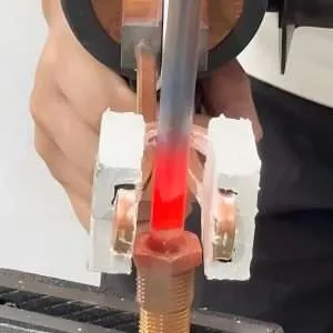
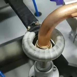
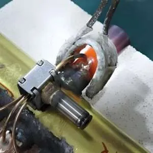
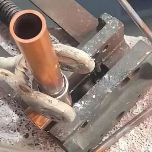
A portable induction brazing machine is a compact, high-frequency induction heating system used to join copper, brass, steel, stainless steel, carbide, diamond tools and mixed-metal assemblies with brazing filler metal. Instead of using an open flame, it generates controlled electromagnetic heat directly inside the joint area. It is widely used for HVAC copper tubes, refrigeration pipelines, automotive components, electrical connectors, carbide tools, diamond segments and stainless steel assemblies. For buyers, it solves common problems such as unstable flame quality, overheating, oxidation, operator dependence, safety concerns and poor repeatability in manual brazing production.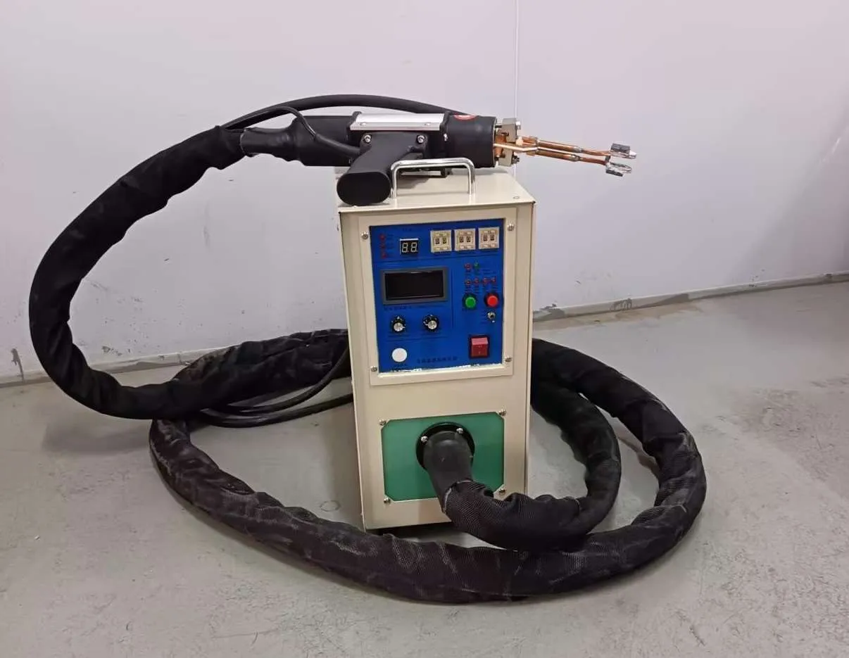
Quick Answer
A portable induction brazing machine is a movable induction heating power supply with a handheld or flexible brazing head, customized copper coil and digital control system. It is best suited for localized brazing of copper tubes, brass fittings, steel joints, stainless steel parts, carbide tools and HVAC/refrigeration pipe assemblies where fast heating, clean joints, repeatable quality and flame-free operation are required.
What Is This Product?
A portable induction brazing machine is an industrial heating device designed to heat a metal joint area quickly and selectively by electromagnetic induction. In brazing, the base metals are not melted. Instead, a filler metal with a lower melting temperature is heated until it flows into the joint gap by capillary action. When the filler solidifies, it forms a strong metallurgical bond between the parts.
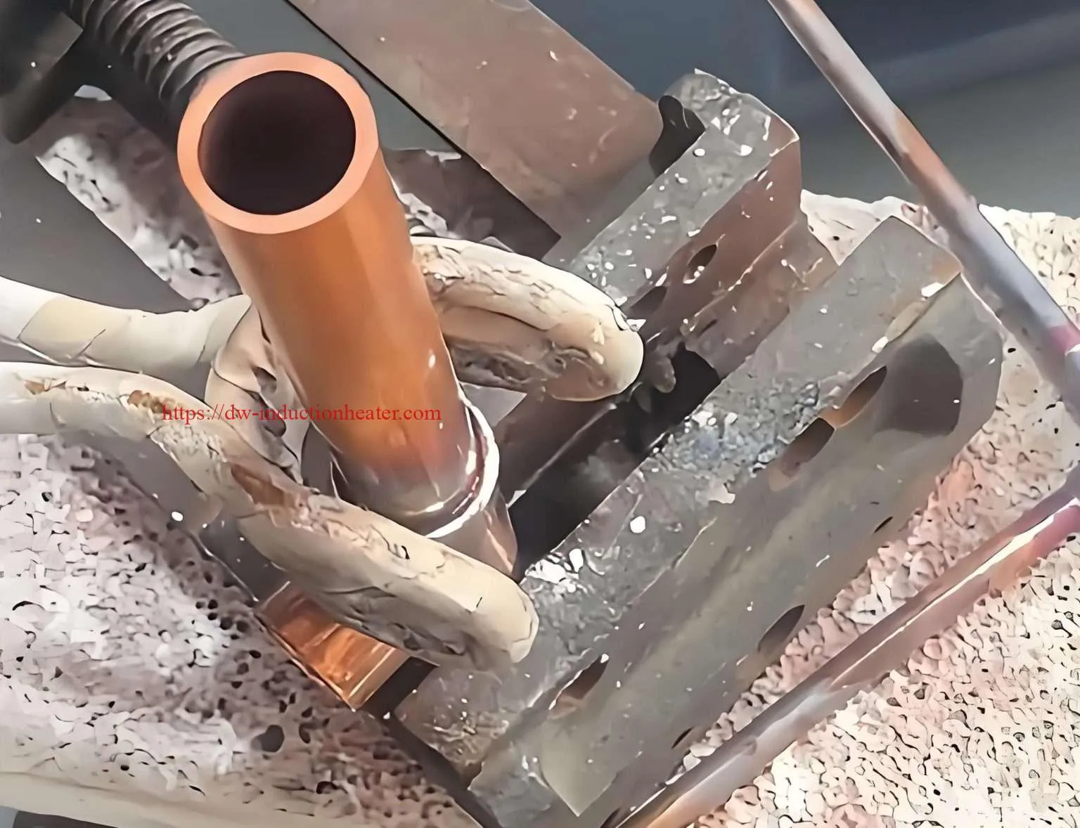
Compared with traditional torch brazing, induction brazing uses an induction coil to deliver heat only where it is needed. The heating area is smaller, the process is easier to control, and the joint quality is more repeatable. For factories that braze copper pipes, brass connectors, stainless steel tubes, carbide tips or diamond cutting segments, this technology can reduce dependence on operator flame skill and improve production consistency.
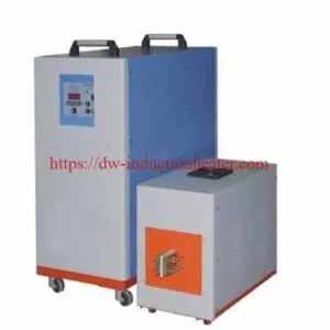
A typical portable induction brazing machine includes an IGBT induction heating power supply, handheld transformer or brazing head, water-cooled copper induction coil, cooling system, foot switch or trigger switch, temperature control option and fixture. According to the application, the machine may be designed as a small bench-top unit, a movable cart-type unit or a handheld flexible cable system.
| System Part | Function | Engineering Notes |
|---|---|---|
| IGBT power supply | Converts input power into high-frequency current | Power and frequency must match the joint size and material |
| Handheld brazing head | Brings the induction coil close to the workpiece | Important for field repair and flexible production |
| Induction coil | Creates the alternating magnetic field | Coil shape determines heating speed and uniformity |
| Cooling system | Cools the power supply, transformer and coil | Water flow protection is recommended |
| Fixture | Positions the parts and controls the joint gap | Improves repeatability and filler flow |
| Control panel | Sets power, time and process mode | Digital control is useful for batch production |
Key Applications
Portable induction brazing machines are used wherever a localized metal joint must be heated quickly, safely and repeatedly. The equipment is especially valuable for pipe joints, small assemblies, service maintenance and production lines where flexible operation is required.
| Industry | Typical Application | Common Workpieces | Main Benefit |
|---|---|---|---|
| HVAC and refrigeration | Copper tube brazing | Copper pipes, elbows, manifolds, compressor tubes | Clean joints without open flame |
| Automotive | Small component brazing | Sensors, tubes, fittings, connectors | Fast cycle time and repeatable heating |
| Tool manufacturing | Carbide tip brazing | Cutting tools, saw blades, drills, milling cutters | Precise heating around the insert seat |
| Diamond tool industry | Diamond segment brazing | Core bits, saw blades, grinding tools | Reduced thermal damage to the tool body |
| Electrical industry | Connector and terminal brazing | Copper terminals, busbars, contacts | High conductivity and stable joint quality |
| Stainless steel fabrication | Tube and fitting brazing | Stainless steel tubes, valves, adapters | Localized heat input and lower distortion |
| Maintenance and repair | On-site brazing | Pipes, fittings, small mechanical parts | Portable and safer than flame in many workshops |
 Application Heat Demand Chart

| Application Type | Heat Demand | Recommended Machine Range | Difficulty Level |
|---|---|---|---|
| Small copper tube joints | Low | 5–15 kW | Easy |
| HVAC distributor and manifold joints | Medium | 15–25 kW | Medium |
| Carbide tool brazing | Medium | 15–35 kW | Medium |
| Large brass valve brazing | High | 25–60 kW | High |
| Stainless steel tube assemblies | Medium to high | 25–60 kW | High |
| Automated multi-station brazing | High | 35–100 kW | High |
Suitable Materials
Induction brazing can be used for most electrically conductive metals. The heating response depends on electrical resistivity, magnetic permeability, part geometry, coil coupling and frequency. Copper and aluminum are highly conductive, so they usually require higher power density and well-designed coils. Carbon steel heats more easily because it has higher resistivity and magnetic properties at lower temperatures. Stainless steel is also suitable, but joint design and filler selection must be carefully controlled.
| Base Material | Induction Heating Response | Common Filler Metal | Typical Application |
|---|---|---|---|
| Copper | Fast heat spreading; requires good coil coupling | Silver-based, copper-phosphorus | HVAC tubes, electrical connectors |
| Brass | Good heating response | Silver-based, brass filler | Valves, fittings, connectors |
| Carbon steel | Very good response below Curie temperature | Silver-based, copper-based, brass filler | Tool holders, mechanical parts |
| Stainless steel | Moderate response; depends on grade | Silver-based, nickel-based | Food, medical, chemical and instrument parts |
| Carbide | Usually heated through holder and insert area | Silver-copper-zinc alloy | Cutting tools and wear parts |
| Diamond segment | Indirect heating through steel body and filler | Silver-based or special brazing alloy | Diamond saw blades and core drills |
| Aluminum | More difficult due to high conductivity and oxide layer | Aluminum-silicon filler | Heat exchangers and light alloy parts |
Material Brazing Difficulty Chart
| Material Combination | Brazing Difficulty | Key Engineering Point |
|---|---|---|
| Copper to copper | Easy | Use correct joint clearance and flux/filler |
| Copper to brass | Easy to medium | Control heat balance between parts |
| Copper to steel | Medium | Heat both parts evenly despite different thermal properties |
| Steel to carbide | Medium | Avoid overheating carbide and maintain insert alignment |
| Stainless steel to stainless steel | Medium to high | Use proper flux, atmosphere or filler selection |
| Aluminum to aluminum | High | Precise temperature control and oxide management are critical |
Working Principle
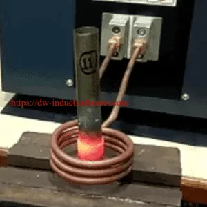
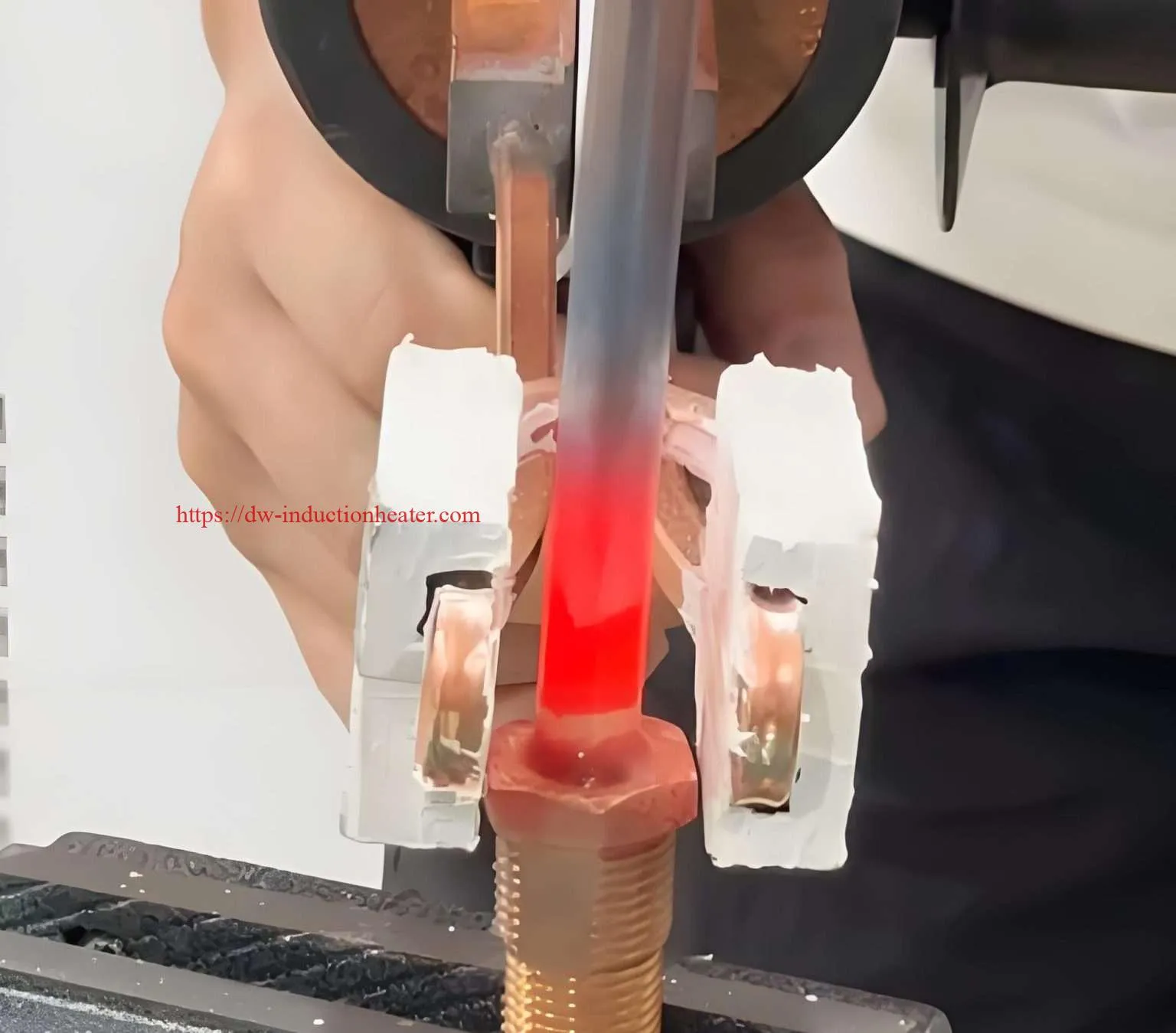
The working principle of a portable induction brazing machine is based on electromagnetic induction. The power supply converts industrial electricity into high-frequency alternating current. This current flows through the copper induction coil and creates a rapidly changing magnetic field. When a conductive metal part is placed inside or near the coil, eddy currents are induced in the workpiece. These eddy currents generate heat due to the electrical resistance of the metal.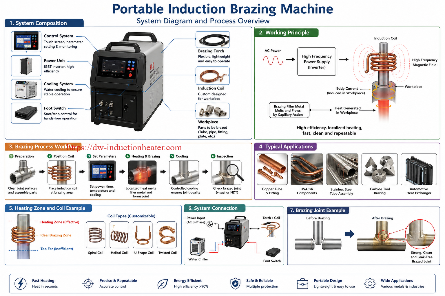
For magnetic metals such as carbon steel, additional heat can be produced by magnetic hysteresis below the Curie temperature. For non-magnetic metals such as copper and brass, heating is mainly caused by eddy current loss. Because the energy is generated directly inside the metal, induction heating is fast, efficient and highly controllable.
Induction Brazing Principle Diagram
| Step | Energy Conversion | Result |
|---|---|---|
| 1 | AC input power enters the IGBT inverter | Stable high-frequency electrical output |
| 2 | High-frequency current flows through copper coil | Alternating magnetic field is generated |
| 3 | Magnetic field couples with the metal joint | Eddy currents are produced in the workpiece |
| 4 | Eddy currents meet metal resistance | Heat is generated at and around the joint |
| 5 | Brazing filler reaches flow temperature | Filler melts and enters the joint clearance |
| 6 | Power stops and joint cools | Strong brazed joint is formed |
Text Process Diagram
Input Power
    ↓
IGBT Inverter
    ↓
High-Frequency Current
    ↓
Copper Induction Coil
    ↓
Alternating Magnetic Field
    ↓
Eddy Current in Workpiece
    ↓
Localized Joint Heating
    ↓
Filler Metal Melting and Flow
    ↓
Brazed Joint Cooling and Solidification
The most important engineering point is that induction heats according to electromagnetic coupling, not only according to the visible position of the flame as in torch brazing. Therefore, the coil shape, coil distance, joint position, material type and filler placement must be designed together. A good induction brazing system is not only a power supply; it is a complete heating solution.
Technical Specifications
| Parameter | Specification | Notes |
|---|---|---|
| Product name | Portable Induction Brazing Machine | Also called handheld induction brazing machine or portable induction heater for brazing |
| Power range | 5 kW–100 kW typical portable range | Higher power available for customized semi-automatic systems |
| Frequency range | 30–300 kHz typical | Higher frequency for small parts and thin joints; lower frequency for larger parts |
| Input voltage | Single phase or three phase, customized | Common options include 220 V, 380 V, 415 V, 440 V and 480 V |
| Power control | Digital power adjustment | Useful for repeatable heating cycles |
| Heating mode | Manual, timer, temperature control or PLC control | Selected according to production requirement |
| Cooling method | Water cooling or integrated chiller | Coil and transformer normally require water cooling |
| Cooling protection | Water flow, water temperature and pressure protection | Recommended for safe long-term operation |
| Operation type | Handheld, bench-top, cart-type or automated station | Portable type is ideal for flexible production and field service |
| Coil type | Custom copper tube coil | Single-turn, multi-turn, U-shape, split coil or pancake coil |
| Applicable filler | Silver, copper-phosphorus, brass, nickel-based and aluminum filler | Depends on base material and joint requirements |
| Temperature range | Typically 600–1150°C depending on filler | Actual process temperature depends on filler alloy |
| Cycle time | Several seconds to several minutes | Depends on joint mass, material and power |
| Control interface | Button panel, digital display, foot switch, handheld trigger or PLC | Optional automation interface available |
| Safety protection | Over-current, over-voltage, over-temperature, water shortage and phase protection | Important for industrial reliability |
Typical Portable Model Reference
| Model Class | Typical Power | Best-Fit Workpiece | Production Style |
|---|---|---|---|
| Small portable unit | 5–10 kW | Small copper tubes, terminals, small rings | Repair, laboratory, small batch |
| General handheld unit | 15–25 kW | HVAC tubes, brass fittings, small carbide tools | Workshop production |
| Industrial portable unit | 30–60 kW | Larger valves, stainless joints, tool bodies | Batch production |
| Semi-automatic brazing station | 60–100 kW | Large assemblies or multi-joint production | Automated or high-volume manufacturing |
Recommended Model Selection
| Application | Material | Recommended Power | Frequency |
|---|---|---|---|
| Small copper tube brazing, diameter below 10 mm | Copper to copper | 5–10 kW | 100–300 kHz |
| HVAC copper tube joints, 10–25 mm | Copper to copper or copper to brass | 10–25 kW | 60–200 kHz |
| Refrigeration compressor tube brazing | Copper, brass, steel | 15–30 kW | 50–150 kHz |
| Brass valve and fitting brazing | Brass to copper or brass to steel | 20–40 kW | 40–120 kHz |
| Carbide tip brazing | Steel holder and carbide insert | 15–35 kW | 80–250 kHz |
| Diamond segment brazing | Steel body and diamond segment | 20–50 kW | 60–180 kHz |
| Stainless steel tube brazing | Stainless steel to stainless steel | 25–60 kW | 30–100 kHz |
| Electrical copper connector brazing | Copper terminal, busbar, contact | 10–40 kW | 60–200 kHz |
| Aluminum tube or heat exchanger brazing | Aluminum alloy | 20–80 kW | 40–150 kHz |
| Automated multi-joint brazing line | Mixed metals | 40–100 kW | 30–150 kHz |
Selection Matrix
| Buyer Requirement | Recommended Configuration | Reason |
|---|---|---|
| On-site repair | Compact portable machine with handheld head | Easy movement and flexible operation |
| Stable batch production | Digital timer control and fixture | Improves process repeatability |
| Thin copper tube brazing | Higher frequency and small custom coil | Fast localized heating |
| Large brass fitting brazing | Higher power with lower frequency | Better heat penetration into larger mass |
| Quality traceability | PLC control and temperature monitoring | Supports process records and parameter management |
| Continuous industrial use | External water chiller and protection system | Improves long-term reliability |
Process Workflow
A stable induction brazing process requires more than heating the joint. The full workflow includes cleaning, joint preparation, filler placement, coil positioning, controlled heating, cooling and inspection. Each step affects the final joint strength and appearance.
Standard Induction Brazing Workflow
| Step | Operation | Engineering Requirement | Quality Check |
|---|---|---|---|
| 1 | Clean the parts | Remove oil, oxide, dust and moisture | Bright and clean joint surface |
| 2 | Prepare joint clearance | Maintain proper gap for capillary flow | No excessive looseness or tight fit |
| 3 | Apply flux or protective atmosphere | Use correct flux for material and filler | Flux covers the heating zone |
| 4 | Place filler metal | Ring, wire, paste, shim or preform | Filler is close to the joint gap |
| 5 | Position coil and fixture | Keep uniform distance around the joint | No contact between coil and workpiece |
| 6 | Start heating cycle | Set power and time according to test result | Filler begins to flow uniformly |
| 7 | Stop power and cool naturally | Avoid moving the joint before solidification | No cracks or displacement |
| 8 | Clean and inspect | Remove flux residue if needed | Check fillet, penetration and strength |
Workflow Diagram
Part Cleaning
    ↓
Joint Assembly
    ↓
Flux / Filler Placement
    ↓
Coil Positioning
    ↓
Power and Time Setting
    ↓
Induction Heating
    ↓
Filler Melting and Capillary Flow
    ↓
Cooling and Solidification
    ↓
Cleaning, Inspection and Testing

Key Process Variables
| Variable | Effect on Brazing | Recommended Control Method |
|---|---|---|
| Power | Controls heating speed | Set according to joint mass and material |
| Frequency | Controls heating depth and coupling | Match part size and coil design |
| Heating time | Affects filler flow and oxidation | Use timer for repeatability |
| Coil distance | Affects heating uniformity | Maintain consistent gap |
| Joint clearance | Affects capillary action | Control with machining or fixture |
| Filler amount | Affects joint strength and appearance | Use preform for batch production |
| Cooling method | Affects residual stress and appearance | Allow stable cooling unless process requires quenching |
Coil and Fixture Design
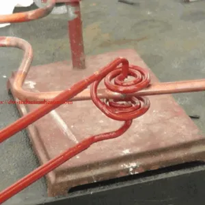
The induction coil is one of the most important parts of a portable induction brazing machine. Even with the correct power supply, poor coil design can cause uneven heating, slow cycle time, filler overburning, overheating of one side, or incomplete brazing. The coil must match the joint shape, material, heating area and production method.
| Coil Type | Best Application | Advantages | Design Notes |
|---|---|---|---|
| Single-turn round coil | Small tube joints and rings | Simple, fast heating, easy operation | Suitable for circular parts |
| Multi-turn helical coil | Longer tube joints and sleeves | More heating length | Requires uniform spacing |
| U-shaped coil | Side-access brazing | Good for parts that cannot pass through a closed coil | Heating may need balancing |
| Split coil | Large fixed assemblies | Easy loading and unloading | Useful for field repair |
| Pancake coil | Flat tools, plates and diamond segments | Good surface heating | Coil-to-part distance must be controlled |
| Custom profile coil | Irregular joint geometry | Best heating uniformity | Requires sample testing and engineering design |
Coil Design Rules
| Design Factor | Recommended Practice | Reason |
|---|---|---|
| Coil-to-part distance | Keep the gap small but safe | Improves electromagnetic coupling |
| Coil position | Center the coil around the brazing joint | Prevents uneven filler flow |
| Coil cooling | Use hollow copper tube with internal water cooling | Prevents coil overheating during continuous operation |
| Turn spacing | Maintain uniform spacing | Improves heating balance |
| Magnetic concentrator | Use when heat must be focused | Increases local heating efficiency |
| Insulation | Avoid direct contact between coil and workpiece | Prevents short circuit and coil damage |
Fixtures are equally important. A proper fixture keeps the joint gap stable, holds the filler metal in position and prevents movement during heating and cooling. For manual brazing, a simple positioning fixture may be enough. For batch production, pneumatic clamps, rotary indexing tables or PLC-controlled fixtures can significantly improve productivity.
Fixture Design Checklist
| Item | Requirement | Why It Matters |
|---|---|---|
| Part alignment | Stable before and during heating | Prevents weak or offset joints |
| Joint clearance | Consistent from part to part | Supports repeatable capillary flow |
| Heat resistance | Fixture material must tolerate radiant heat | Prevents fixture deformation |
| Electrical behavior | Avoid unnecessary conductive loops near coil | Prevents unwanted heating |
| Loading speed | Easy part loading and unloading | Improves production efficiency |
Control System and Automation
Portable induction brazing machines can be operated manually or integrated into semi-automatic production stations. The control level should be selected according to production volume, quality requirement and operator skill. For repair and small-batch work, manual trigger operation is flexible. For repeated production, timer control, temperature monitoring and PLC programs are recommended.
| Control Level | Configuration | Best Application | Benefit |
|---|---|---|---|
| Manual control | Power adjustment and handheld trigger | Repair, trial production, flexible work | Simple and economical |
| Timer control | Preset heating time and power | Batch production of similar parts | Improves repeatability |
| Temperature control | Infrared pyrometer or thermocouple feedback | Precision brazing and sensitive materials | Reduces overheating risk |
| PLC control | Recipe storage, sensors and interlocks | Production lines and automation | Supports stable industrial process |
| Robot integration | Robot-held coil or part handling | High-volume manufacturing | Reduces labor and improves consistency |
Automation Option Chart
| Production Volume | Recommended Control | Recommended Accessories |
|---|---|---|
| Low volume | Manual mode | Handheld head, foot switch, simple fixture |
| Medium volume | Timer mode | Digital panel, water chiller, positioning fixture |
| High volume | PLC mode | Pneumatic fixture, rotary table, cooling monitoring |
| Quality-critical production | Temperature feedback mode | Pyrometer, data logging, alarm system |
| Fully automated line | PLC and robot integration | Robot arm, automatic loading, safety enclosure |
Common Problems and Solutions
| Problem | Possible Cause | Engineering Solution |
|---|---|---|
| Filler does not flow | Temperature too low, poor cleaning, wrong filler or too small joint clearance | Increase power or time, clean surface, select correct filler and adjust clearance |
| Filler balls up | Oxidation, poor flux, surface contamination or uneven heating | Improve cleaning, apply correct flux, adjust coil position |
| Joint overheats | Power too high or heating time too long | Reduce power, shorten cycle time or use temperature feedback |
| One side heats faster | Coil not centered or parts have different mass | Redesign coil, rotate part or change coil distance |
| Weak joint strength | Poor capillary flow, wrong filler, incorrect gap or insufficient heating | Optimize joint design and verify brazing temperature |
| Excessive oxidation | Heating time too long or flux is insufficient | Shorten cycle, use proper flux or protective atmosphere |
| Coil overheats | Insufficient cooling water or excessive current | Check water flow, coil tube blockage and cooling system |
| Machine alarms frequently | Water flow, over-current, over-voltage or overload issue | Check input power, cooling system and coil matching |
| Inconsistent cycle results | Manual variation, unstable part position or inconsistent filler amount | Use fixture, timer control and preformed filler rings |
Defect Diagnosis Chart
| Observed Defect | Likely Process Issue | Priority Check |
|---|---|---|
| Black joint surface | Oxidation or overheated flux | Heating time and flux type |
| Incomplete fillet | Insufficient heat or filler | Power, time and filler placement |
| Cracked joint | Movement during cooling or thermal stress | Fixture stability and cooling method |
| Excess filler outside joint | Too much filler or poor gap control | Filler size and joint clearance |
| Base metal discoloration | Overheating or excessive heat-affected zone | Coil position and power setting |
Engineering Selection Guide
Selecting a portable induction brazing machine should begin with the workpiece, not only with the power rating. The same 25 kW machine may work very well for one copper tube joint but may be too small for a large brass valve or too powerful for a tiny electrical terminal. A good selection requires analysis of material, joint size, filler metal, production quantity, operator method and required quality level.
Step 1: Define the Joint
The joint geometry determines coil shape and power demand. Tube-to-tube joints, tube-to-fitting joints, flat tool joints and ring joints all need different coil designs. Engineers should measure outside diameter, wall thickness, overlap length, joint clearance and total heated mass.
Step 2: Confirm the Material Combination
Copper, brass, steel, stainless steel, carbide and aluminum all heat differently. Mixed-metal joints require heat balance. For example, copper conducts heat away quickly, while steel may heat faster under the same coil. The coil may need to focus more energy on the copper side or increase heating length to create uniform filler flow.
Step 3: Select Filler Metal and Brazing Temperature
The filler metal determines the required process temperature. Silver-based filler is widely used for high-quality copper, brass, steel and carbide brazing. Copper-phosphorus filler is common for copper-to-copper applications. Nickel-based filler may be used for stainless steel or high-temperature service. Aluminum brazing requires very precise temperature control because the melting range of the base material and filler is relatively close.
Step 4: Estimate Power and Frequency
Small parts need high frequency and lower power. Larger parts need more power and often a lower frequency for better heating depth. In portable brazing, 10–25 kW covers many copper tube and HVAC applications, while 30–60 kW is more suitable for larger brass, steel and stainless steel assemblies.
Step 5: Design Coil and Fixture
After selecting a machine power range, the coil and fixture should be tested with actual samples. The best coil is not always the most complicated coil. It is the coil that heats the joint uniformly, allows easy loading, avoids short circuit risk and provides stable results over many cycles.
Step 6: Verify by Sample Test
Before mass production, sample testing is strongly recommended. A proper test should record power, frequency, heating time, filler flow, joint appearance, pull strength or leak test result, and operator feedback. These records become the foundation for production process parameters.
| Selection Question | Why It Matters | Example Answer |
|---|---|---|
| What is the workpiece material? | Determines heating response and filler selection | Copper tube to brass fitting |
| What is the joint size? | Determines power and coil size | 22 mm tube diameter, 1 mm wall thickness |
| What filler metal is used? | Determines target temperature | Silver brazing ring |
| How many parts per hour? | Determines automation level and cooling demand | 300 joints per hour |
| Manual or automated? | Determines machine structure | Handheld with timer mode |
| What quality test is required? | Determines process control level | Leak test and visual inspection |
Advantages
Portable induction brazing offers strong practical advantages for modern metal joining production. It is cleaner, safer and easier to standardize than flame brazing in many applications.
| Advantage | Engineering Value | Buyer Benefit |
|---|---|---|
| Flame-free heating | No open flame at the joint | Improves workshop safety |
| Localized heat input | Heat is concentrated around the joint | Reduces distortion and discoloration |
| Fast heating speed | Energy is generated directly in the metal | Shorter cycle time |
| Good repeatability | Power and time can be digitally controlled | Stable joint quality |
| Cleaner working environment | Less smoke and less wide-area heating | Improves operator comfort |
| Easy automation | Can integrate with PLC, fixture and robot | Suitable for production lines |
| Lower operator dependence | Less reliance on torch angle and flame skill | Easier training and quality control |
| Energy efficiency | Heat is focused on the joint area | Reduces wasted heat |
| Portable operation | Machine can move near the workpiece | Useful for repair and flexible production |
Comparison: Induction Brazing vs Flame Brazing
| Item | Portable Induction Brazing | Flame Brazing |
|---|---|---|
| Heat source | Electromagnetic induction | Combustion flame |
| Heat control | Digital power and time control | Manual flame adjustment |
| Safety | No open flame | Open flame and gas storage required |
| Repeatability | High with fixture and timer | Depends strongly on operator skill |
| Heating area | Localized | Wider heat-affected area |
| Automation | Easy to integrate | More difficult |
| Initial cost | Higher machine investment | Lower initial equipment cost |
| Long-term production cost | Often lower in batch production | Gas consumption and labor variation remain |
| Best use | Repeatable industrial brazing | Simple repair or low-volume work |
Limitations
Although portable induction brazing is powerful and efficient, it is not suitable for every joint without engineering adjustment. Buyers should understand its limitations before selecting a machine.
| Limitation | Explanation | Recommended Solution |
|---|---|---|
| Requires coil design | Different parts often need different coils | Provide samples or drawings before machine selection |
| Initial cost is higher than torch brazing | Power supply, coil and cooling system increase investment | Evaluate total production cost and quality improvement |
| Not all geometries are easy to access | Closed coils may not fit complex assemblies | Use U-shaped, split or custom profile coils |
| Aluminum brazing is more difficult | Temperature window is narrow and oxide layer is challenging | Use precise control, correct flux and sample testing |
| Cooling water is usually required | Coil and transformer need cooling during operation | Use industrial chiller and water flow protection |
| Operator still needs training | Part cleaning, filler placement and coil position matter | Create standard operating procedures |
In engineering practice, most limitations can be solved by correct coil design, good fixturing, suitable filler selection and sample testing. The machine should be considered as part of a complete brazing process, not as a standalone heat source only.
Why Choose HLQ Induction Equipment?
HLQ Induction Equipment focuses on industrial induction heating solutions for brazing, hardening, forging, melting, annealing, shrink fitting, PWHT and other metal heating processes. For portable induction brazing machines, the most important value is not only selling a power supply, but also helping customers match the machine, coil, cooling system and process parameters to the actual workpiece.
| HLQ Capability | Customer Value | Application Example |
|---|---|---|
| Wide induction heating product range | Supports different power and frequency requirements | Small tube brazing to large industrial joining |
| Custom induction coil design | Improves heating uniformity and cycle time | Copper tube, brass fitting, carbide tool and diamond segment brazing |
| Engineering selection support | Reduces wrong machine selection risk | Power and frequency recommendation by workpiece size |
| Portable and industrial configurations | Suitable for repair, workshop and production line use | Handheld brazing head or automated fixture station |
| Process testing mindset | Improves practical brazing success rate | Sample heating test before final production solution |
| OEM and custom solution ability | Supports different voltage, layout and automation needs | Special machine for HVAC, tool or automotive industry |
For buyers who are changing from flame brazing to induction brazing, HLQ can help evaluate the current joint, filler metal, target cycle time and production environment. The recommended solution may include a portable induction brazing machine, customized coil, cooling water system, fixture, timer control and optional temperature monitoring. This engineering-based approach helps customers obtain stable joint quality instead of only purchasing a standard machine.
FAQ
1. What is a portable induction brazing machine?
A portable induction brazing machine is a compact induction heating system used to heat a metal joint and melt brazing filler metal. It usually includes an induction power supply, handheld brazing head, water-cooled coil and control system.
2. What materials can it braze?
It can braze copper, brass, carbon steel, stainless steel, carbide, diamond tool segments and some aluminum alloys. The exact process depends on filler metal, joint design and coil configuration.
3. Is induction brazing better than flame brazing?
For repeatable industrial production, induction brazing is often better because it provides localized heating, digital control, higher repeatability and no open flame. Flame brazing may still be suitable for simple low-volume repair work.
4. What power should I choose for copper tube brazing?
Small copper tubes often use 5–15 kW. Medium HVAC tube joints usually use 10–25 kW. Larger brass or copper assemblies may require 25–60 kW depending on size, heating time and filler metal.
5. What frequency is suitable for induction brazing?
Portable brazing applications commonly use high frequency ranges such as 30–300 kHz. Small parts usually need higher frequency, while larger parts may need lower frequency and higher power.
6. Does the induction coil need water cooling?
Yes, most industrial induction brazing coils are made from hollow copper tube with internal water cooling. Cooling protects the coil and transformer during continuous operation.
7. Can one machine braze different parts?
Yes, one power supply can often braze different parts by changing the induction coil, fixture and process parameters. However, very different workpiece sizes may require different power ranges.
8. Can it be used for HVAC and refrigeration pipe brazing?
Yes. HVAC copper tube and refrigeration pipe brazing are among the most common applications. Induction brazing can produce clean, consistent joints without open flame near sensitive components.
9. Can induction brazing be automated?
Yes. The machine can be integrated with PLC control, pneumatic fixtures, rotary tables, temperature monitoring and robotic handling for semi-automatic or fully automatic production.
10. What information is needed to select the right machine?
The key information includes material, joint size, wall thickness, filler metal, target heating time, production quantity, available voltage, manual or automatic operation, and quality testing requirement.
11. Why does filler metal not flow during brazing?
Common reasons include insufficient temperature, poor surface cleaning, wrong filler metal, incorrect joint clearance, poor flux or uneven heating. The solution is to optimize cleaning, power, heating time, filler selection and coil position.
12. Can portable induction brazing reduce production cost?
In batch production, it can reduce cost by improving cycle time, reducing rework, lowering operator dependence and improving joint consistency. The total saving depends on production volume and current brazing method.
13. Is induction brazing safe?
Induction brazing avoids open flame and gas combustion, which improves safety in many workshops. Operators still need training for electrical safety, hot parts, cooling water and proper coil handling.
14. Can aluminum be brazed by induction?
Yes, but aluminum brazing is more difficult than copper or steel brazing because the temperature window is narrow and the oxide layer must be controlled. Accurate process testing is recommended.
15. Why choose a customized induction brazing coil?
A customized coil improves heating uniformity, shortens cycle time and prevents overheating. It is one of the most important parts of a successful induction brazing process.