

Quench and Temper Line for Steel Rods vs Steel Tubes
Induction Quench and Temper Line for Steel Rods vs Steel Tubes: Engineering Comparison for Induction Heat Treatment
Table of Contents
- Quick Answer
- Comparison Overview
- Working Principle Comparison
- Key Technical Parameters
- Efficiency and Energy Cost Comparison
- Temperature Control Comparison
- Material Quality and Surface Condition
- Safety and Compliance Comparison
- Maintenance Comparison
- Total Cost of Ownership
- Engineering Selection Guide
- Common Engineering Mistakes
- Common Problems and Solutions
- Real Project Case Study
- Honest Limitations of Both Methods
- Final Recommendation
- FAQ
Steel rods and steel tubes can run through the same type of induction quench and temper (Q&T) line: medium frequency hardening coils, a quench, tempering, cooling and straightening. They should not be specified the same way, though. A rod must be heated and hardened through its full diameter, while a tube only needs its wall heated and hardened. That one difference changes the frequency, the energy per metre, the hardenability check and the quench design. This guide is for heat-treatment engineers, OCTG and mechanical-tube producers, and buyers of Q&T lines who process rods, tubes or both.
Quick Answer
Neither product is “better”; each needs its own settings on the line.
- Solid rods: specify by diameter. Large rods need low frequency and enough time for heat to reach the core; HLQ lines run 8–15 kHz for Ø 15–40 mm and 2–4 kHz for Ø 50–150 mm. Check that the grade can through-harden at that diameter; Ovako states that 42CrMo4 through-hardens in oil up to Ø 60 mm.
- Tubes: specify by OD and wall thickness. Match the frequency to the wall; HLQ tube heating systems run 10–30 kHz for 2–10 mm walls and 0.5–10 kHz for 10–100 mm walls. At the same OD, a tube needs much less energy per metre because it has only 36–44% of the rod’s mass in the examples below.
One line can process both if it has coil sets, PLC recipes and quench settings for each product.
Comparison Overview
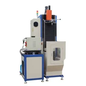
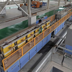
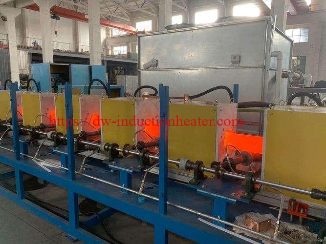
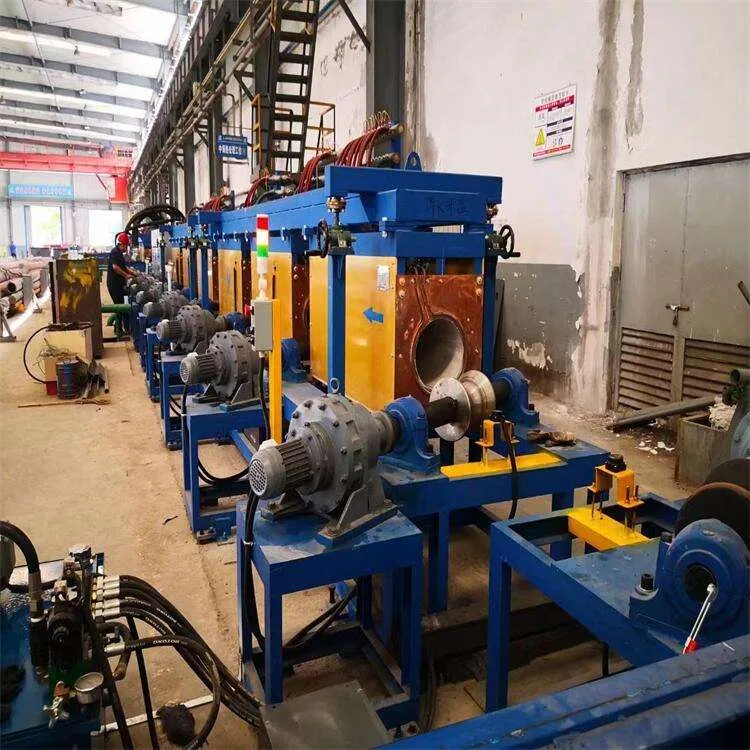
An induction Q&T line heats each workpiece to its austenitizing temperature, quenches it to form martensite, then tempers it to the required hardness and toughness. Skew rollers rotate and advance the product so that heating and quenching act evenly around it, and the line ends with cooling, straightening and bundling. HLQ builds these lines for bars, shafts and tubes; see the induction quench and temper steel bar line.
Typical products from the HLQ Q&T line page:
- Rods: drive and axle shafts, torsion and stabilizer bars, pins, bucket rods, drill rods, sucker rods and high-strength bolts.
- Tubes: casing, tubing and coupling sleeves, mechanical tubes and hydraulic cylinders.
Working Principle Comparison

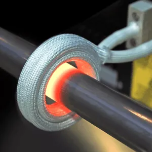
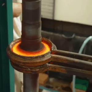
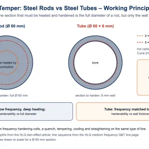
In both cases, the induced current flows mainly in a surface layer whose depth depends on frequency. For hot carbon steel above the Curie point, HLQ’s skin effect in induction heating data gives about 16.6 mm at 1 kHz and 5.25 mm at 10 kHz.
- Rod: the core is reached by conduction from the heated outer layer, so large rods need low frequency and enough heating time for the whole section to reach temperature.
- Tube: the wall is the whole section. When the current depth suits the wall thickness, the wall heats through quickly. Thin walls therefore call for higher frequencies than large solid rods.
Key Technical Parameters
| Parameter | Steel Rods | Steel Tubes | Engineering Impact |
|---|---|---|---|
| Section to heat and harden | Full diameter | Wall thickness | Sets frequency and hardenability check |
| Size range (HLQ) | Ø 15–150 mm, 2–14 m long on MF-Q&T lines | Pipe Ø 20–1500 mm, wall 2–100 mm across MF-25 to MF-500 tube heating systems | Machine and coil selection |
| Frequency (HLQ) | 8–15 kHz (Ø 15–40) down to 2–4 kHz (Ø 50–150) | 10–30 kHz (wall 2–10 mm) down to 0.5–10 kHz (wall 10–100 mm) | Thin walls need higher frequency |
| Mass per metre (calculated) | Ø 60 mm: 22.2 kg/m | Ø 60 × 6 mm: 8.0 kg/m | Energy per metre and line speed |
| Process data (HLQ) | 42CrMo: quench 840–880 °C, temper 540–620 °C, 32–40 HRC | Alloy tube: quench 850–900 °C, temper 550–650 °C, 28–36 HRC | Separate recipes |
| Quench medium (HLQ) | Oil / polymer for 40Cr, 42CrMo, 35CrMo; water / polymer for 45# | Water / polymer for alloy tubes | Quench system design |
| Hardenability check | Against full diameter (e.g. 42CrMo4: Ø 60 mm in oil) | Against wall thickness | Grade selection |
| Typical standards | EN 10083 steels for quenching and tempering | API 5CT for OCTG casing and tubing | Acceptance criteria differ |

Efficiency and Energy Cost Comparison
The heat needed is driven by mass. HLQ’s tube heating page gives the heating time as t = (m × Cp × ΔT) / (P × η), with Cp typically 460–500 J/kg·°C for steel. For the same outside diameter, a tube carries much less steel per metre:
| Section | Rod mass | Tube mass | Tube / rod |
|---|---|---|---|
| Ø 40 rod / Ø 40 × 5 mm tube | 9.86 kg/m | 4.32 kg/m | 44% |
| Ø 60 rod / Ø 60 × 6 mm tube | 22.2 kg/m | 7.99 kg/m | 36% |
| Ø 100 rod / Ø 100 × 10 mm tube | 61.65 kg/m | 22.2 kg/m | 36% |
Masses are calculated for steel at 7850 kg/m³. In practice:
- A line sized for rods by tonnes per hour can run tubes of the same OD faster per metre, if the coil and frequency suit the wall.
- Energy cost per tonne is driven by temperature rise and efficiency rather than by product shape.
Use measured line data for cost calculations.
Temperature Control Comparison
Both products are controlled the same way on HLQ lines:
- Real-time monitoring of power, frequency, temperature, line speed and quench parameters.
- Pyrometer feedback and PLC recipes per diameter and steel grade.
The difference is what has to be uniform:
- Rods: core and surface must both reach temperature, so heating time and frequency matter for large diameters.
- Tubes: the full wall and the whole circumference must be even. HLQ lists ±3–5 °C temperature control with pyrometer feedback for its tube heating systems.
Keep pyrometer lenses clean of steam and smoke to avoid false readings.
Material Quality and Surface Condition
- Rods: the main limit is hardenability against diameter. Ovako states that 42CrMo4 through-hardens in oil up to Ø 60 mm, and larger sections are not fully martensitic. For C45 in the quenched and tempered condition, EN 10083-2 values in the Saarstahl data sheet drop from 700–850 MPa tensile strength (d ≤ 16 mm) to 630–780 MPa (40 < d ≤ 100 mm).
- Tubes: the wall is the section to harden, so wall thickness, not OD, is the dimension to compare with the grade’s hardenability. HLQ’s published data does not specify internal (bore) quenching, so the quench design must be confirmed for each tube project.
- Both: skew-roller rotation keeps heating and quenching even around the circumference, and straightening units correct the remaining bend. See the quenching and tempering steel bar process guide for process windows and testing.
Safety and Compliance Comparison
| Topic | Steel Rods | Steel Tubes |
|---|---|---|
| Electrical | Medium frequency power supplies; IEC 60519 series for electroheating installations | Same |
| Hot product handling | Rotating hot rods on skew rollers; cooling bed | Rotating hot tubes on skew rollers; cooling bed |
| Quench system | Oil, polymer or water depending on grade | Water or polymer for alloy tubes (HLQ data) |
| Product standards | EN 10083 steel grades | API 5CT for OCTG casing and tubing |
Maintenance Comparison
Maintenance is the same for both products, because the line is the same:
- Clean oxide scale from the coils to prevent arcing.
- Run the closed-loop cooling circuit on clean, distilled water.
- Clean and calibrate the pyrometers.
- Maintain the quenchant filtration and cooling.
The extra effort comes from product variety. Every additional rod diameter or tube size may need its own coil set, so keep quick-change coil assemblies organized by size.
Total Cost of Ownership
- Rod-only line: sized by the largest diameter and the required tonnes per hour; HLQ MF-Q&T models run from 150 to 1000 kW.
- Tube-only line: sized by OD and wall range; thin-wall tubes need higher-frequency power supplies.
- Combined line: one line with extra coil sets and recipes is usually cheaper than two separate lines, but changeovers take time, and the frequency range must cover both the largest rod and the thinnest wall.
For a structured sizing method, see how to select an induction quench and temper line.
Engineering Selection Guide

| Condition | Recommended Option | Reason |
|---|---|---|
| Solid rods Ø 15–40 mm | Rod line, MF-Q&T-150 (8–15 kHz) | HLQ model matched to this diameter range |
| Solid rods Ø 50–150 mm | Rod line, MF-Q&T-1000 (2–4 kHz) | Low frequency for deep heating of large sections |
| Thin-wall tubes (wall 2–10 mm) | Tube heating at higher frequency (HLQ MF-25: 10–30 kHz) | Current depth must suit the wall |
| Heavy-wall or large tubes (wall 10–100 mm) | Lower frequency, higher power (HLQ MF-500: 0.5–10 kHz) | Deeper heating for thick walls |
| Both rods and tubes in one plant | Combined line with coil sets and recipes | One line, product-specific settings |
| Rod diameter beyond the grade’s hardenability | Change grade or accept size-band properties | The core will not fully harden |
| OCTG casing and tubing | Tube line with a project-specific quench design | API 5CT acceptance; bore quench not covered by HLQ published data |
For tube heating equipment ranges, see induction pipe and tube heating.
Common Engineering Mistakes
- Sizing a tube like a rod of the same OD: the wall, not the OD, decides frequency and hardenability.
- Using rod frequencies on thin-wall tubes: a low frequency suited to a large rod is inefficient for a thin wall.
- Ignoring hardenability for large rods: a grade that through-hardens at Ø 40 mm may not at Ø 100 mm.
- Assuming one quench design fits both: confirm the quench medium and spray design for each product and grade.
- Underestimating changeovers: each size may need its own coil; plan quick-change assemblies and recipes.
- Using brochure efficiency figures for cost: base energy costs on measured line data.
Common Problems and Solutions
| Problem | Product | Solution |
|---|---|---|
| Core softer than the surface | Rods | Lower frequency, longer heating; check hardenability against diameter |
| Uneven wall heating | Tubes | Match frequency to the wall; keep the coil concentric and the tube rotating |
| Bent product after quenching | Both | Skew-roller rotation; straightener after the cooling bed |
| Hardness below target | Both | Correct quench medium for the grade; check quench flow, pressure and temperature |
| Temperature readings drift | Both | Clean pyrometer lenses; calibrate |
| Low efficiency after a size change | Both | Change to the coil set for that diameter or OD |

Real Project Case Study
HLQ publishes line data for both product types, intended as a starting point for sizing:
| Q&T line model | Power | Frequency | Rod Ø | Length | Output |
|---|---|---|---|---|---|
| MF-Q&T-150 | 150 kW | 8–15 kHz | 15–40 mm | 2–6 m | 0.3–0.8 t/h |
| MF-Q&T-300 | 300 kW | 5–10 kHz | 20–60 mm | 3–8 m | 0.6–1.5 t/h |
| MF-Q&T-500 | 500 kW | 3–8 kHz | 30–80 mm | 4–10 m | 1.0–2.5 t/h |
| MF-Q&T-800 | 800 kW | 3–5 kHz | 40–120 mm | 4–12 m | 2.0–4.0 t/h |
| MF-Q&T-1000 | 1000 kW | 2–4 kHz | 50–150 mm | 5–14 m | 3.0–5.0 t/h |
| Tube heating system | Power | Frequency | Pipe Ø | Wall | Heating length |
|---|---|---|---|---|---|
| MF-25 | 25 kW | 10–30 kHz | 20–100 mm | 2–10 mm | 100–300 mm |
| MF-50 | 50 kW | 5–25 kHz | 50–200 mm | 3–15 mm | 150–500 mm |
| MF-100 | 100 kW | 3–20 kHz | 100–400 mm | 5–25 mm | 200–800 mm |
| MF-200 | 200 kW | 1–15 kHz | 200–800 mm | 8–40 mm | 300–1200 mm |
| MF-500 | 500 kW | 0.5–10 kHz | 400–1500 mm | 10–100 mm | 500–2000 mm |
A measured rod heating reference from HLQ: a 0.795″ (20.19 mm) diameter, 15″ (381 mm) steel blank was heated to about 1500 °F (816 °C) in 9.90 seconds with a DW-MF-90kW at 20 kHz and a fifteen-turn helical coil. That job was preheating for forming, not a Q&T recipe. Customer-specific Q&T results for rods and tubes are available on request for qualified projects.
Honest Limitations of Both Methods
- Rods:
- Through-hardening is limited by the grade’s hardenability; large diameters reach lower size-band properties.
- Large rods need high power and low frequency.
- Tubes:
- The quench design, including any bore quenching, must be engineered per project; HLQ’s published data does not cover it.
- Thin walls need higher-frequency equipment than rods.
- Combined lines:
- More coil sets and recipes to manage.
- Changeover time between products.
- The frequency range must cover both the largest rod and the thinnest wall.
Final Recommendation
- Size rods by diameter: choose a frequency low enough to heat the core, check the grade’s hardenability at the largest diameter, and select the MF-Q&T model by diameter and tonnes per hour.
- Size tubes by wall: match frequency to wall thickness, size power by mass per metre and line speed, and engineer the quench for the tube.
- Plants that run both: one line with coil sets, recipes and quench settings for each product is usually the most practical choice.
Compared with batch furnaces, see induction vs furnace quenching and tempering.
FAQ
Can one quench and temper line process both rods and tubes?
Yes, with coil sets for each size, PLC recipes and quench settings for each product. The line sequence stays the same.
How is the induction frequency chosen for rods and tubes?
Rods by diameter (8–15 kHz for Ø 15–40 mm down to 2–4 kHz for Ø 50–150 mm on HLQ lines); tubes by wall thickness (10–30 kHz for 2–10 mm walls down to 0.5–10 kHz for 10–100 mm walls).
Why does a tube need less energy per metre than a rod?
At the same outside diameter, a tube contains less steel: 36–44% of the rod mass in the examples given.
Which dimension decides hardenability?
The full diameter for rods, and the wall thickness for tubes.
Which quench medium is used?
HLQ data: oil or polymer for 40Cr, 42CrMo and 35CrMo; water or polymer for 45# steel and alloy tubes.
What hardness can be reached?
For example, 32–40 HRC for 42CrMo rods and 28–36 HRC for alloy tubes on HLQ lines.
Is internal quenching of tubes included?
HLQ’s published data does not specify bore quenching; the quench design is confirmed for each tube project.
What information is needed for a quotation?
Rod diameters and tube sizes (OD × wall), lengths, steel grades, hardness and strength targets, output in t/h, and the available power, water and floor space.