
How to Remove 3LPE Pipeline Coating: An Engineer’s Guide to Induction Coating Removal
Quick Engineering Answer
Induction heating is one of the most practical methods for removing thick 3LPE coatings from carbon-steel pipelines when localized coating removal is required for inspection, repair, welding, recoating or pipeline rehabilitation.
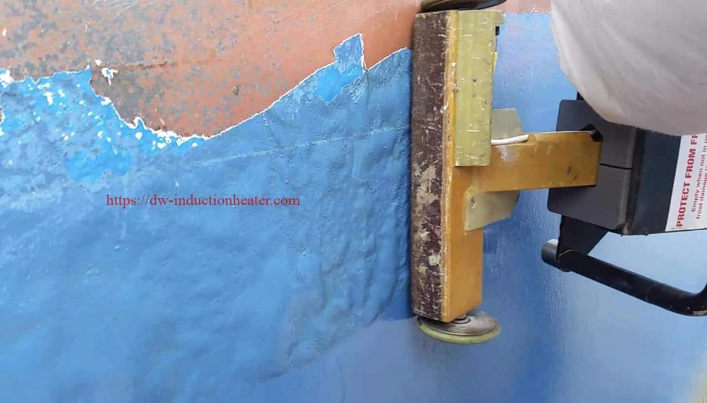
Instead of mechanically grinding through the polyethylene, adhesive and FBE layers one after another, an induction system generates controlled heat directly in the steel pipe wall. Heat travels toward the steel/FBE interface, reducing adhesion and allowing the 3LPE coating to be peeled or scraped away in strips or comparatively large sections.
For many field applications, 30–60 kW induction coating removal equipment provides a practical starting range. However, actual machine power must be selected according to pipe diameter, wall thickness, coating thickness, heating-head area and required productivity.

“Can induction heating remove 3LPE?”
The more useful questions are:
- How much energy must be transferred into the pipe wall?
- What temperature is required at the steel/coating interface?
- How should the induction head match the pipe curvature?
- Should a 30 kW or 60 kW generator be selected?
- How fast can the heating head move?
- How can overheating of the steel be avoided?
- Does induction eliminate the need for abrasive blasting?
The answers depend on both electromagnetic heating and the thermal-mechanical behavior of the coating system.
The process uses the same physical principles as electromagnetic induction heating, but the heating process is optimized specifically for coating-to-steel disbonding.
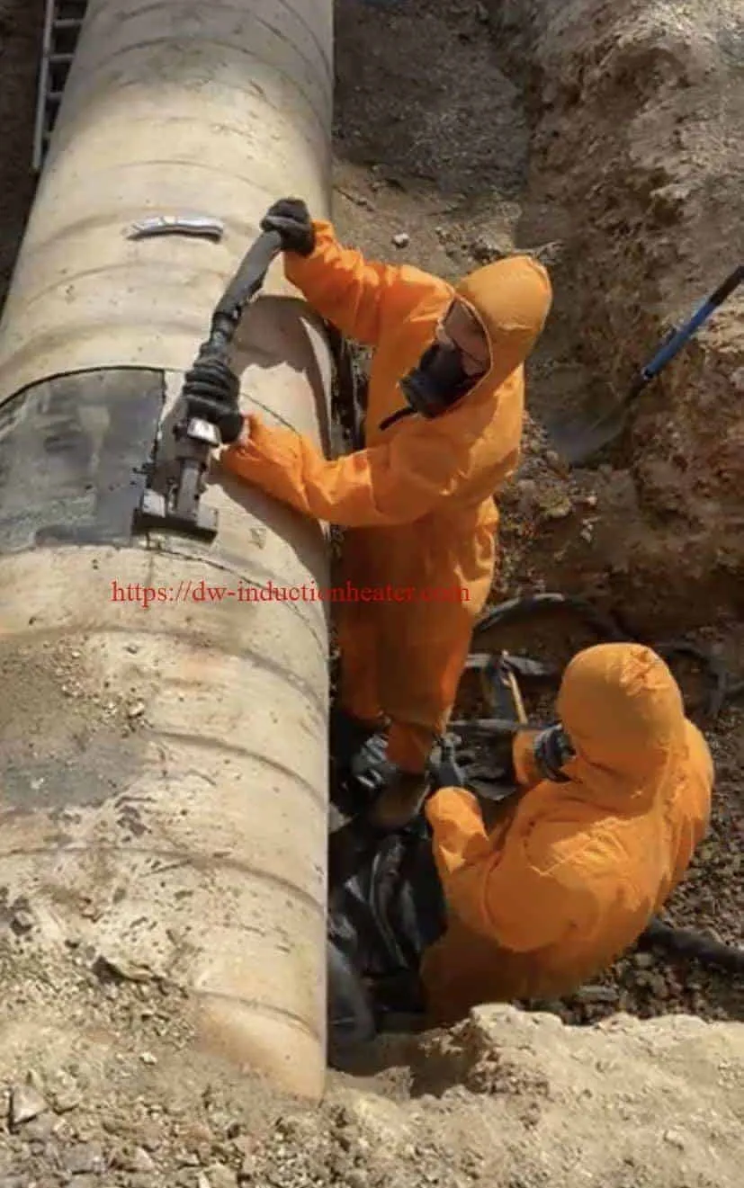
What Is a 3LPE Pipeline Coating?
3LPE means three-layer polyethylene coating. It is widely used as an external corrosion-protection system for buried, onshore and offshore carbon-steel pipelines.
Unlike ordinary industrial paint, 3LPE is an engineered multilayer system designed to provide both chemical corrosion resistance and mechanical protection.
Typical 3LPE Layer Structure
| Layer | Typical Material | Primary Function | Removal Challenge |
|---|---|---|---|
| Layer 1 | Fusion Bonded Epoxy (FBE) | Corrosion protection and adhesion to steel | Strong bond to blast-cleaned steel substrate |
| Layer 2 | Copolymer Adhesive | Bonds FBE to polyethylene | Maintains strong interface between layers |
| Layer 3 | Polyethylene (PE) | Mechanical, moisture and impact protection | Thick, tough and resistant to mechanical removal |
Depending on pipeline specification, diameter and service environment, the complete coating system can be several millimeters thick.
This multilayer construction explains why 3LPE is much more difficult to remove than conventional paint.
Why Conventional 3LPE Removal Can Be Difficult
An engineer normally evaluates coating removal based on three factors:
- How much coating material must physically be destroyed?
- How much secondary waste will be generated?
- What condition must the steel have after removal?
Grinding or blasting attacks the coating from the outer PE layer toward the steel.
This means the full coating thickness must be mechanically processed.
Induction works differently.
The objective is to weaken the weakest functional location for removal:
Steel → FBE → Adhesive → Polyethylene
Rather than pulverizing all three layers, controlled induction heating can weaken the coating system near its interface with the pipe.
This is why a dedicated induction pipeline coating removal system can be particularly useful for localized pipeline maintenance.
How Does Induction Heating Remove 3LPE Coating?
The physics of the process is relatively straightforward, but successful field operation requires control of several variables.
Step 1 — Alternating Current Flows Through the Induction Coil
The induction generator converts mains electrical power into controlled medium- or high-frequency alternating current.
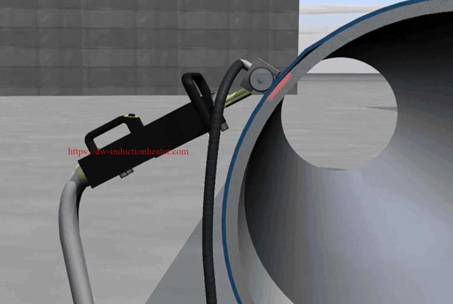
This current is transmitted through a long-distance cable to the copper induction coil inside the handheld heating head.
Step 2 — The Coil Generates an Alternating Magnetic Field
The alternating current creates a rapidly changing electromagnetic field around the coil.
The heating head itself does not need to physically contact the steel to generate heat.
Step 3 — Eddy Currents Are Generated in the Steel Pipe
When the induction head approaches the carbon-steel pipeline, the magnetic field induces electrical currents in the steel.
The electrical resistance of the steel converts these currents into heat.
Therefore:
Step 4 — Heat Reaches the FBE/Steel Interface
The steel surface beneath the coating heats rapidly.
Thermal energy passes from the steel into the first FBE layer and then through the adhesive system.
The objective is not to heat the whole pipeline uniformly.
The objective is localized thermal conditioning of the coating interface.
Step 5 — Adhesion Decreases
Once the coating system reaches an appropriate process window, adhesive strength decreases and the polyethylene system becomes easier to mechanically separate.
Step 6 — The Operator Removes the Coating
A scraper, peeling blade or other mechanical tool follows the induction head.
Under suitable conditions, the coating can separate as:
- Long strips
- Sheets
- Large flakes
- Sections of multilayer coating
Key Engineering Parameters for 3LPE Induction Removal
There is no single universal setting for every pipeline.
The main parameters are interconnected.
| Parameter | Engineering Effect | What Happens If Incorrect? |
|---|---|---|
| Generator Power | Controls available heating rate | Too low = slow disbonding; excessive = harder process control |
| Operating Frequency | Influences electromagnetic coupling and heating distribution | Poor frequency match reduces process efficiency |
| Pipe Wall Thickness | Determines thermal mass | Thick wall requires more energy or slower travel |
| Pipe Diameter | Determines induction-head curvature | Poor curvature match reduces coupling |
| 3LPE Thickness | Affects thermal resistance and removal behavior | Thicker systems may require slower operation |
| Head-to-Pipe Distance | Directly affects coupling efficiency | Excessive gap reduces heating efficiency |
| Scanning Speed | Determines heat input per unit area | Too fast = incomplete release; too slow = overheating |
| Coil Width | Determines treated area per pass | Wide coil requires more power |
| Scraper Timing | Determines how easily softened coating can be removed | Waiting too long allows the interface to cool |
What Power Is Required for 3LPE Pipeline Coating Removal?
For many portable or handheld applications, HLQ systems are available in approximately 30–60 kW power classes. Your website’s pipeline-removal system lists 30–60 kW equipment and long-distance working cables for field coating-removal applications.
The following table is a practical engineering selection guide rather than a guaranteed performance specification.
| Application Condition | Suggested Starting Power Class | Engineering Reason |
|---|---|---|
| Small localized repair area | 30 kW | Good control and mobility |
| Medium pipe / moderate wall thickness | 30–40 kW | Balanced power and handheld operation |
| Larger-diameter pipeline | 40–60 kW | Larger heating footprint may be required |
| Thick-wall pipeline | 60 kW | Greater steel thermal mass |
| High productivity requirement | 60 kW | Supports wider head or faster movement |
| Automated coating stripping | 60 kW or application-specific | Automation can use higher continuous heat input effectively |
These systems belong to the broader family of induction stripping and coating removal equipment used for polyethylene, epoxy, rubber, coal tar and other bonded coatings on steel.
30kW vs 60kW for Pipeline Coating Removal
| Parameter | 30kW System | 60kW System |
|---|---|---|
| Mobility | Higher | Moderate |
| Electrical Demand | Lower | Higher |
| Handheld Control | Very good | Requires disciplined scanning |
| Moderate Wall Pipe | Good candidate | More capacity than necessary in some jobs |
| Thick-Wall Pipe | Slower heating | Preferred |
| Large Heating Head | Limited | Better suited |
| Potential Productivity | Medium | Higher |
| Automated Process | Possible | Better suited |
A critical engineering point is that doubling the generator power does not automatically double completed square meters per hour.
Once heating becomes fast enough, the bottleneck can move from induction power to:
- Scraping
- PE handling
- Waste collection
- Operator movement
- Pipeline access
- Final surface cleaning
Why Pipeline Induction-Head Design Is Critical
For flat steel, a flat heating head can provide relatively uniform coupling.
A round pipeline is more difficult.
If a flat coil is held over a small pipe, the center of the coil may be close to the steel while the edges are farther away.
This produces uneven electromagnetic coupling and an uneven temperature field.
An Engineer Should Consider:
- Pipeline OD
- Coil arc radius
- Effective working width
- Copper-tube geometry
- Magnetic flux distribution
- Stand-off distance
- Cooling-water flow
- Mechanical protection of the coil
For repeatable industrial stripping, the heating head should follow the pipeline radius as closely as practical.
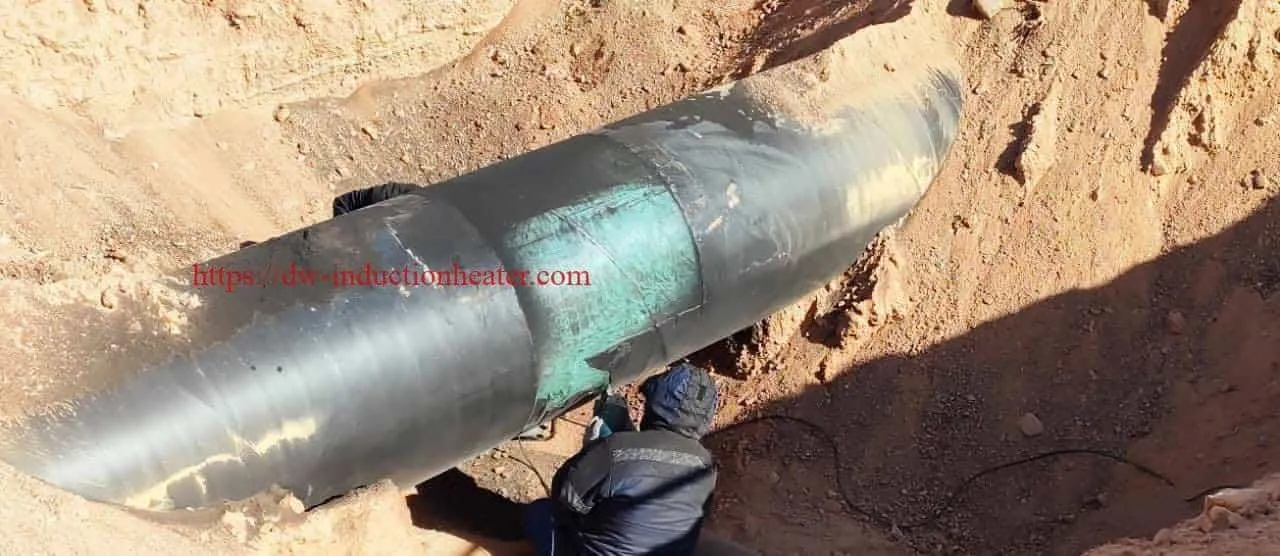
Recommended Field Procedure for Removing 3LPE
1. Collect Pipeline Data Before Testing
Before selecting settings, record:
- Steel grade
- Pipe OD
- Wall thickness
- 3LPE total thickness
- Coating manufacturer if known
- Pipeline service
- Required removal length
- Whether pipeline is operating or shut down
2. Test a Small Qualification Area
Do not begin a large pipeline project using maximum power.
A more controlled approach is to qualify a small section first.
For example:
200–300 mm axial coating length × selected pipe circumference area
Start at moderate power and controlled travel speed.
3. Increase Heat Input Gradually
There are two basic ways to increase energy density:
- Increase generator power
- Reduce scanning speed
Changing travel speed is often the finer control method during process development.
4. Observe Coating Behavior
The desired result is not necessarily bubbling or heavy smoke.
Look instead for:
- Edge lifting
- Loss of adhesion
- Easy scraper penetration
- Large strip removal
- Reduced scraping force
5. Follow Immediately with a Scraper
Once the heating head moves away, the steel begins cooling.
Removing the coating while the interface remains thermally weakened usually produces better results.
6. Record the Qualified Process Window
| Recorded Parameter | Example Field Record |
|---|---|
| Generator output | XX% |
| Heating-head width | XX mm |
| Stand-off distance | XX mm |
| Travel speed | XX m/min |
| Measured steel temperature | XX°C |
| Coating-removal behavior | Strip / sheet / partial |
| Removal productivity | XX m²/h |
| Average power | XX kW |
This turns an operator-dependent process into a reproducible engineering procedure.
Induction Disbonding Temperature: Avoid a Universal Number
One common mistake in coating-removal articles is giving one “correct” removal temperature.
For 3LPE, the correct process temperature depends on:
- FBE formulation
- Adhesive chemistry
- PE grade
- Coating age
- Wall thickness
- Ambient temperature
- Existing adhesion
Consequently, temperature should be treated as a qualified process variable, not a fixed universal setting.
This is also why controlled induction disbonding technology should combine temperature observation with coating-release behavior rather than relying only on one thermometer reading.
Temperature Measurement Challenges on 3LPE
Infrared temperature measurement can be misleading because the infrared camera may see the polyethylene outer surface rather than the steel/FBE interface.
Potential errors include:
- Unknown PE emissivity
- Surface color
- Reflections
- Temperature gradient through the coating
- Moving or peeled coating
Recommended Qualification Method
During initial testing, combine:
- Infrared thermal imaging
- Contact thermocouple measurements where accessible
- Power recording
- Travel-speed measurement
- Visual coating-release assessment
The most useful parameter is ultimately the process condition that produces reliable disbonding without unnecessary steel heating.
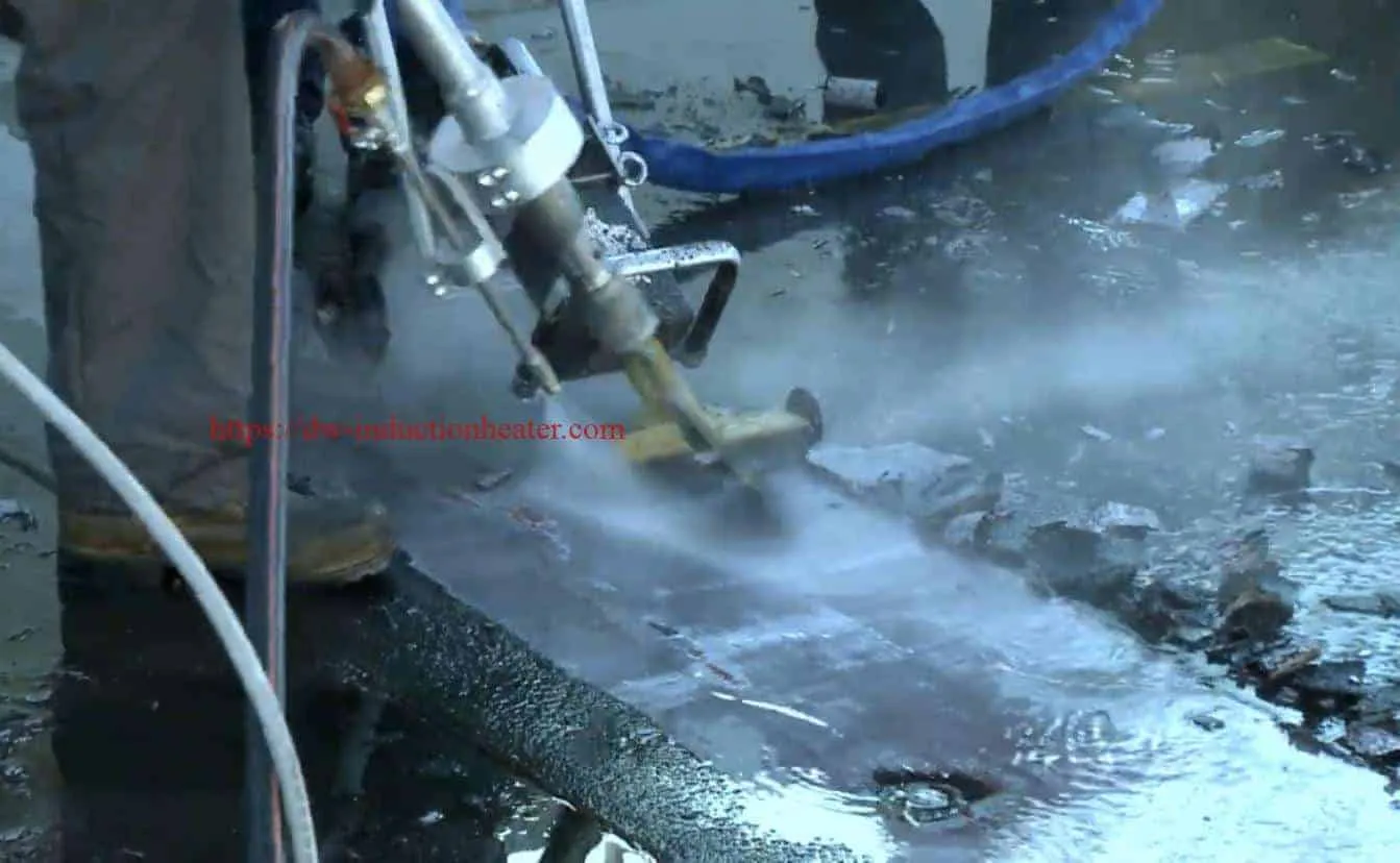
Induction vs Abrasive Blasting for 3LPE Removal
| Engineering Factor | Induction Removal | Abrasive Blasting |
|---|---|---|
| Primary Mechanism | Thermal disbonding | Mechanical erosion |
| Bulk 3LPE Removal | Strong application | Possible but abrasive intensive |
| Abrasive Media | Not required during bulk stripping | Required |
| Waste Type | Mainly coating pieces | Coating + abrasive mixture |
| Dust | Generally lower during peeling | Potentially significant |
| Steel Profile | Minimal change | Creates anchor profile |
| Steel Removal | Minimal when controlled | Abrasive action intentionally affects surface |
| Final Recoating Preparation | May require secondary preparation | Can be integrated |
From an engineering point of view, the most realistic comparison is often not:
Induction OR blasting.
It is:
This approach avoids using expensive abrasive media simply to destroy several millimeters of polyethylene.
Induction vs Grinding vs UHP Water Jetting vs Laser
| Method | 3LPE Bulk Removal | Secondary Waste | Surface Profiling | Key Limitation |
|---|---|---|---|---|
| Induction | Excellent candidate | Relatively low | No | Requires conductive steel and controlled heating |
| Grinding | Possible | Polymer debris + discs | Localized | Slow and labor intensive |
| Abrasive Blasting | Effective | High | Excellent | Media consumption and containment |
| UHP Water | Effective | Wastewater | Limited | Water handling and flash rust |
| Laser | Application dependent | Fine process emissions | Limited | Large coating volume must be ablated |
Energy Consumption: How Engineers Should Calculate It
Electrical energy consumption should be expressed per unit of removed area rather than simply quoting generator kW.
The useful relationship is:
Specific Energy Consumption (kWh/m²)
Average Electrical Power (kW)
÷
Net Removal Productivity (m²/h)
Example Calculation
Assume:
- Average generator load = 24 kW
- Cooling and auxiliaries = 1.5 kW
- Net coating-removal rate = 4 m²/h
Total power:
24 + 1.5 = 25.5 kW
Specific energy:
25.5 ÷ 4 = 6.38 kWh/m²
Illustrative Electricity Cost
| Electricity Cost | Specific Consumption | Electricity Cost per m² |
|---|---|---|
| US$0.08/kWh | 6.38 kWh/m² | US$0.51/m² |
| US$0.12/kWh | 6.38 kWh/m² | US$0.77/m² |
| US$0.20/kWh | 6.38 kWh/m² | US$1.28/m² |
| US$0.30/kWh | 6.38 kWh/m² | US$1.91/m² |
This calculation is an engineering example, not a guaranteed equipment-performance figure. Actual consumption must be measured during application testing.
Why Long-Distance Cable Matters in Pipeline Work
Pipeline coating removal is rarely performed next to the induction generator.
Typical field conditions include:
- Pipe trenches
- Remote rights-of-way
- Pipeline racks
- Offshore modules
- Limited vehicle access
- Elevated pipework
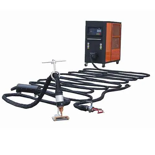
A long-distance cable therefore allows the power supply and cooling equipment to remain in a practical operating location while the operator moves the lightweight heating head along the pipeline.
HLQ pipeline systems are designed around this concept and are part of its broader range of induction coating removal from steel surfaces.
Example Engineering Case: 610mm Pipeline with 3LPE
The following is an illustrative engineering evaluation rather than a guaranteed field-performance claim.
| Parameter | Example Condition |
|---|---|
| Pipeline Material | Carbon steel |
| Outside Diameter | 610 mm |
| Wall Thickness | 12 mm |
| External Coating | 3LPE |
| Coating Thickness | Approx. 3 mm |
| Removal Length | 1.5 m axial length |
| Initial Power Selection | 30–60 kW test range |
| Heating Head | Curved handheld induction head |
| Cable Length | 20–40 m |
| Operation | Manual controlled scanning |
| Purpose | Inspection and recoating |
Recommended Test Procedure
- Mark a 200–300 mm qualification section.
- Start with moderate generator power.
- Establish stable heating-head movement.
- Observe coating edge release.
- Reduce travel speed gradually if adhesion remains strong.
- Increase power only when required.
- Follow immediately with mechanical peeling.
- Measure temperature and record conditions.
- Inspect the exposed steel.
- Repeat the test until stable removal is achieved.
This approach identifies the lowest practical thermal input that gives repeatable removal.
Does Induction Eliminate Final Surface Preparation?
No—not necessarily.
This distinction is critical for pipeline engineers.
Removing the 3LPE system exposes the steel, but the steel may still contain:
- Residual FBE
- Primer residue
- Corrosion
- Surface salts
- Old adhesive
- Contamination
A replacement coating specification may require a defined cleanliness level and anchor profile.
Therefore a robust workflow is:
| Stage | Process | Purpose |
|---|---|---|
| 1 | Induction heating | Disbond 3LPE from steel |
| 2 | Mechanical peeling | Remove bulk coating |
| 3 | Steel inspection | Identify corrosion or defects |
| 4 | Light blasting / mechanical cleaning | Remove residue and create profile |
| 5 | Surface verification | Confirm coating specification |
| 6 | Recoat | Restore corrosion protection |
Safety Considerations for Live and In-Service Pipelines
Pipeline induction coating removal should be treated as a controlled thermal process.
For an operating pipeline, the allowable pipe-wall temperature cannot simply be copied from another application.
The pipeline owner or responsible engineer must consider:
- Product inside the pipeline
- Operating pressure
- Steel grade
- Wall thickness
- Existing defects
- External corrosion
- Internal flow
- Maximum allowable wall temperature
- Hazardous-area requirements
Additional site controls include:
- Electrical safety
- Electromagnetic-field procedures
- Hot-surface protection
- Ventilation
- Polymer fume control
- Cooling-water monitoring
- Fire protection
- Personal protective equipment
A live hydrocarbon pipeline should never be heated without an approved engineering procedure and site-specific thermal limits.
How to Select a 3LPE Pipeline Coating Removal Machine
A machine supplier should not recommend equipment based solely on the statement:
“We need to remove 3LPE.”
The following information should be supplied first.
| Required Customer Data | Why It Is Required |
|---|---|
| Steel grade | Determines material behavior and temperature limits |
| Pipeline OD | Determines heating-head curvature |
| Wall thickness | Determines thermal mass |
| 3LPE thickness | Affects heat transfer and peeling |
| Removal length | Determines project scale |
| Required m²/h | Influences generator power |
| Pipeline operating condition | Critical for thermal safety |
| Required cable length | Determines field configuration |
| Electrical supply | Determines generator input design |
| Application photos | Helps evaluate access and geometry |
A physical coated pipe sample is highly recommended before final equipment selection.
HLQ provides several RPR induction coating removal heaters for different pipeline, tank, marine and industrial coating-removal requirements.
Frequently Asked Questions About 3LPE Pipeline Coating Removal
Can induction heating remove 3LPE pipeline coating?
Yes. Carbon-steel pipelines are particularly suitable for induction heating because the steel couples efficiently with the electromagnetic field. The generated heat can weaken the FBE/coating interface and allow 3LPE to be peeled mechanically.
Can a 30kW induction heater remove 3LPE?
Yes, 30 kW can be a suitable starting power for many localized pipeline maintenance applications. Large pipe diameters, thick walls, wider heads or high productivity requirements may favor 60 kW.
What temperature is required to remove 3LPE?
There is no universal temperature. FBE formulation, adhesive system, polyethylene grade, coating age, pipe thickness and operating conditions all influence the required disbonding temperature. A sample test is the correct method for establishing the process window.
Does the polyethylene have to melt?
No. Complete melting is not the objective. Ideally the coating softens sufficiently and loses interfacial adhesion so it can be removed in strips or larger pieces.
Can induction remove 3LPP as well?
Yes. 3LPP is also a potential induction-disbonding application, although polypropylene has different thermal behavior and should be qualified separately.
Can induction remove coal tar coatings?
Yes. Coal tar, coal tar epoxy, rubber and several other strongly bonded pipeline coating systems can also be evaluated for induction removal.
Does induction damage the pipeline steel?
A correctly controlled process is designed to provide localized surface heating without exceeding the permitted steel temperature. The acceptable limit must be defined for the particular pipe and operating condition.
Does induction completely replace abrasive blasting?
Not necessarily. Induction is highly suitable for bulk coating removal. Abrasive blasting may still be used afterward when a defined cleanliness grade or anchor profile is required.
How fast is induction 3LPE removal?
There is no universal m²/h value. Productivity depends on wall thickness, pipe diameter, coating condition, generator power, head design, travel speed and scraping method. Sample testing is required for credible production estimates.
Why is sample testing important?
Testing establishes the actual power, travel speed, temperature, coil geometry and coating-release behavior before the machine is committed to a field project.
Conclusion: The Engineering Approach to Removing 3LPE Pipeline Coating
3LPE pipeline coating removal is fundamentally different from removing conventional paint because the coating consists of a strongly bonded FBE layer, adhesive layer and tough polyethylene outer layer.
Induction heating offers a particularly useful engineering solution because it does not need to mechanically destroy the entire coating thickness.
Instead, electromagnetic energy produces localized heat inside the steel substrate, allowing the coating-to-steel interface to be thermally weakened.
The coating can then be peeled or scraped away in strips or large pieces.
However, successful induction coating removal is not simply a matter of applying maximum kW.
The process must balance:
Generator Power
+
Operating Frequency
+
Pipe Wall Thickness
+
Heating-Head Curvature
+
Coupling Distance
+
Travel Speed
+
Disbonding Temperature
+
Scraper Timing
For localized repair work and moderate pipe sections, a 30 kW system can often provide a practical starting point.
For thicker pipe walls, larger pipe diameters, wider induction heads or higher productivity, a 60 kW system may be more appropriate.
Most importantly, the preferred process is to determine the lowest stable thermal input that produces repeatable coating release, rather than operating continuously at maximum temperature.
For pipeline rehabilitation projects, induction should also be viewed as the bulk coating-removal stage. If the replacement coating requires a specified cleanliness level or anchor profile, final abrasive or mechanical surface preparation may still be necessary.
Need to Test Your 3LPE Pipeline Coating?
For an engineering equipment recommendation, provide:
- Pipeline outside diameter
- Pipe wall thickness
- Steel grade
- 3LPE coating thickness
- Total coating-removal length
- Required productivity
- Pipeline operating condition
- Available electrical supply
- Required cable length
- Pipeline photos or drawings
A physical section of coated pipe is the preferred basis for application testing and final machine selection.