
HVAC induction brazing machines join copper tubes
HVAC Induction Brazing Machine for Copper and Brass Tube Joints
The HLQ HVAC induction brazing machine replaces open-torch brazing on air-conditioning and refrigeration assemblies with fast, flame-free, repeatable electromagnetic heating. It is built around the water-cooled DW-HF high frequency series (15 kW to 45 kW, 30–80 kHz) and a coil shaped around each joint, so copper tubes, brass fittings, distributors and compressor connections are heated only where the filler alloy must flow.

Quick Answer
An HVAC induction brazing machine is a high frequency induction heating system that heats a copper or brass tube joint until the brazing filler (copper-phosphorus, copper-phosphorus-silver or silver alloy) melts and is drawn into the joint clearance by capillary action. In HLQ’s documented copper-tube HVAC applications, joints are brazed at approximately 700–800 °C with about 6–15 kW and roughly 5–20 seconds of heating per joint. For most HVAC copper pipe and brass fitting work, HLQ recommends a 15–35 kW high frequency machine as the starting point, and 40–60 kW for larger distributors or multiple joints.
Table of Contents
- Quick Answer
- What is the HVAC Induction Brazing Machine?
- Key Applications
- Suitable Materials
- Working Principle
- Technical Specifications
- Recommended Model Selection
- Process Workflow
- Common Problems and Solutions
- Engineering Selection Guide
- Advantages and Limitations
- Why Choose HLQ?
- 10 Core FAQs
What is the HVAC Induction Brazing Machine?
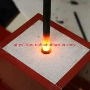
The HVAC induction brazing machine is an induction brazing machine configured for the tube joints found in air conditioners, heat pumps, condensing units and refrigeration systems. Instead of a gas flame, it sends high frequency current through a water-cooled copper coil placed around the joint. The alternating magnetic field induces eddy currents in the tube and fitting, so heat is generated inside the joint area itself.
Brazing joins the parts without melting the base metals: only the filler, with a liquidus above 450 °C (840 °F), melts and flows into the joint gap. Refrigeration piping is brazed rather than soft-soldered because a brazed joint is strong and leak-free and withstands the high and low temperatures and pressures of the refrigerant circuit.
A complete HLQ HVAC brazing station normally includes:
| System part | Function in HVAC brazing |
|---|---|
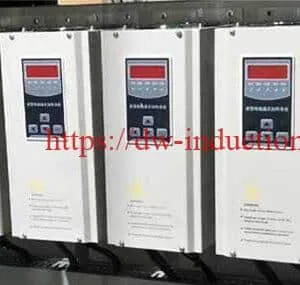
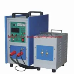
| DW-HF induction power supply | Converts mains power into 30–80 kHz high frequency current; power and heating time are set manually or by timer |
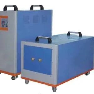
| Extension unit (HF transformer) | Separates the heating head from the power unit so the coil can sit close to the workpiece |
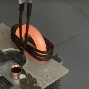
| Induction coil | C-coil, U-coil, helical coil or custom-shaped coil formed around the tube joint |
| Locating fixture | Holds tube and fitting concentric and keeps the joint still until the filler solidifies |
| Cooling water system | Cools the power supply, transformer and coil; a closed-loop chiller is recommended for continuous production |
| Temperature control (optional) | Time control, pyrometer or thermocouple for repeatable joint temperature |
The same power supply can be set up for manual bench work, handheld operation, semi-automatic stations or robotic HVAC assembly lines by changing the coil, fixture and control level.
Key Applications
Air conditioners contain many brazed joints, mostly in copper and aluminium. Typical HVAC and refrigeration brazing tasks handled with HLQ induction equipment include:
| HVAC joint | Typical parts | Usual coil style | Main benefit of induction |
|---|---|---|---|
| Copper tube to copper tube | Condenser and evaporator piping, U-bends, socket joints | Helical or C-shaped coil | Even circumferential heating and repeatable joint quality |
| Copper tube to brass fitting | Valves, service ports, brass bodies, reducers | Helical coil biased toward the heavier brass part | Heat balance between parts of different mass |
| Distributor and manifold | Several small tubes into a distributor or header | Custom coil for one-shot heating of multiple joints | Replaces tedious hand torch work and reduces leak risk |
| Compressor connections | Compressor inlet and outlet tubing | Split or U-shaped coil for side access | Localized heat near sensitive components, no open flame |
| Heat exchanger assemblies | Heat exchanger tube ends, heating elements | Custom coil | Consistent joints in batch production |
| Aluminium connections | Evaporator and condenser tube-to-tube, tube-to-block, tube-to-tank | Custom coil with precise temperature control | Controlled heat for a narrow aluminium process window |
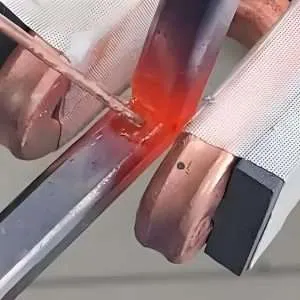
For copper and brass line sets, refrigeration pipes and the documented copper-pipe cases, see induction brazing HVAC pipes. Where the joint is installed equipment or a compressor stub with limited access, a portable induction brazing machine with a handheld head brings the coil to the joint.
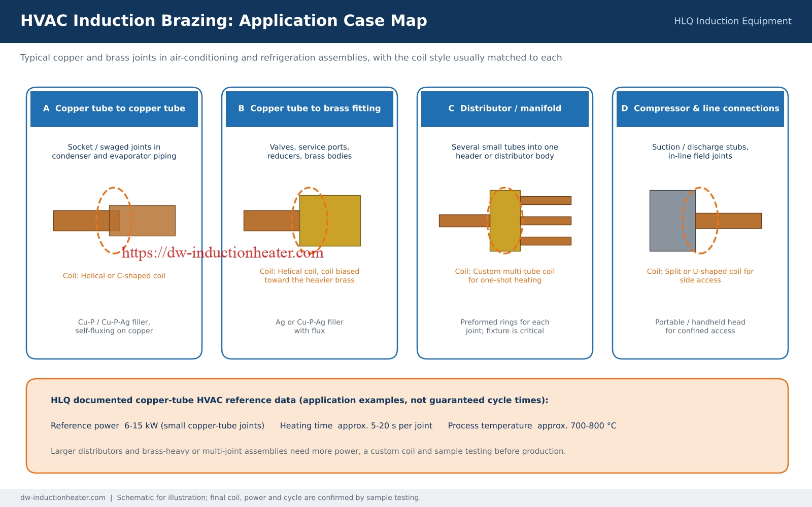
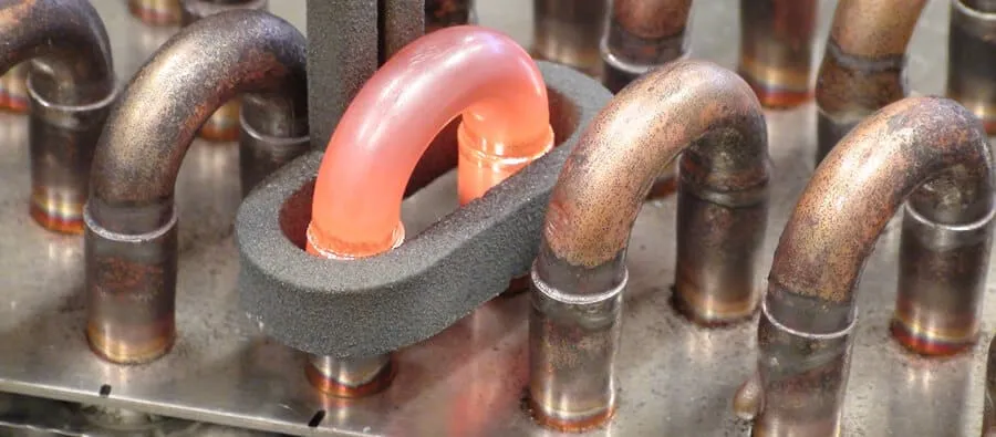

Application case reference data (HLQ documented copper-tube HVAC work)
| Parameter | Documented value | Note |
|---|---|---|
| Reference power | 6–15 kW | Small copper-tube joints |
| Heating time | Approx. 5–20 s per joint | About 5 s in one heat-exchanger case, about 20 s in another copper-pipe case |
| Process temperature | Approx. 700–800 °C | Set by the filler alloy and base materials |
| Filler metal | Cu-P, Cu-P-Ag or silver brazing alloy | Application dependent |
| Operation | Manual, handheld, semi-automatic or robotic | Chosen by production volume |
These values are application examples, not guaranteed cycle times. Larger distributors, brass-heavy fittings and multi-joint assemblies need more power and a sample test.
Suitable Materials
Induction heating works on any electrically conductive metal, but heating response differs. Copper conducts heat away quickly and needs good coil coupling and enough power. Brass responds well but must not be overheated, to avoid zinc evaporation and discoloration. Aluminium has a narrow window between brazing temperature and base-metal melting.
| Base material / combination | Brazing suitability | Common filler | Engineering note |
|---|---|---|---|
| Copper to copper | Excellent | Copper-phosphorus (Cu-P), Cu-P-Ag | High conductivity; use correct clearance and good coil coupling |
| Copper to brass | Excellent | Silver alloy, Cu-P-Ag | Balance heat toward the heavier brass part; flux is needed on brass |
| Brass | Excellent | Silver alloy, brass brazing alloy | Control temperature to avoid zinc evaporation |
| Copper to steel | Good | Silver alloy, copper alloy | Different heating rates; coil and fixture balancing needed |
| Stainless steel | Good | Silver alloy, nickel alloy | Benefits from flux or protective atmosphere |
| Aluminium | Possible, more difficult | Aluminium-silicon filler | Precise temperature control and oxide management; sample testing recommended |
Filler alloys used on HVAC copper joints
| Filler type | Typical use | Practical note |
|---|---|---|
| Copper-phosphorus (Cu-P) | Copper-to-copper joints | Self-fluxing on copper; not intended for steel or nickel alloys |
| Copper-phosphorus-silver, 15% Ag | Standard alloy for refrigeration service and repair joints | Better flow and joint quality than low-silver grades |
| Copper-phosphorus-silver, 5% Ag | Lower-cost copper joints | Cheaper, but does not perform as well as 15% Ag |
| Silver brazing alloy (Ag-based) | Copper to brass, copper to steel, stainless steel | Used with a suitable flux |
Select the filler in this order: base materials, joint design, operating pressure, operating temperature, applicable HVAC/refrigeration standards, then production requirements.
Working Principle
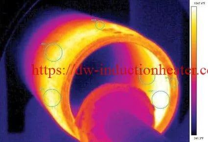
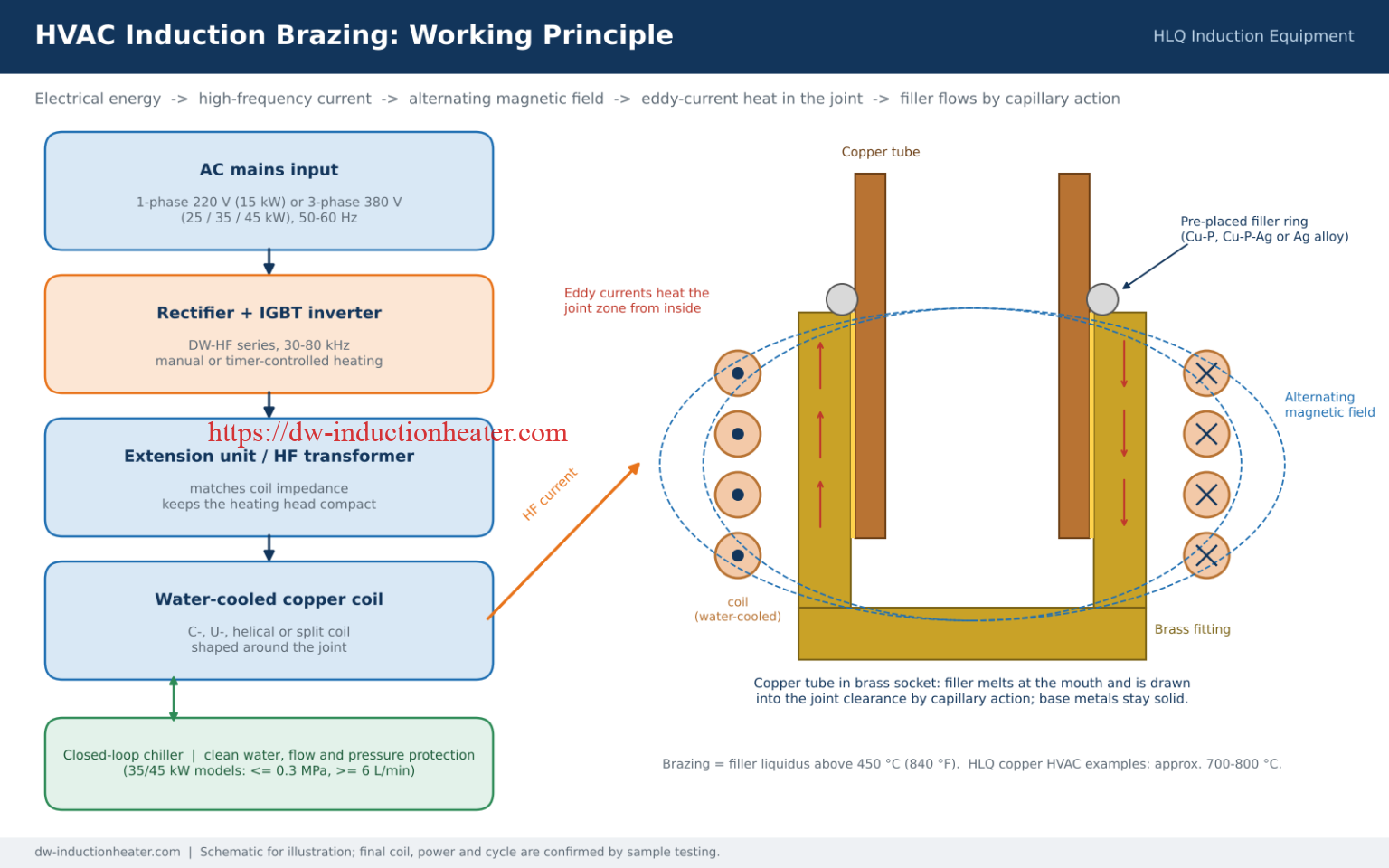
The HVAC brazing machine uses high frequency induction heating. The power supply rectifies mains power and an IGBT inverter converts it into 30–80 kHz alternating current. This current flows through the water-cooled copper coil and creates an alternating magnetic field around the tube joint. Eddy currents induced in the copper tube and fitting meet the metal’s electrical resistance and produce heat inside the joint zone. The coil itself stays cool because water flows through it.
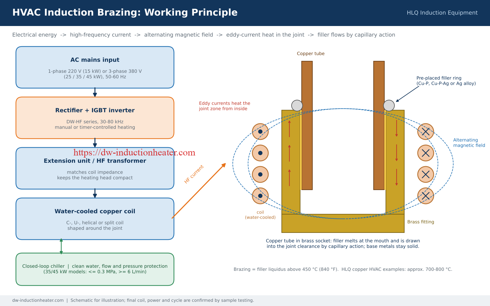
| Stage | Physical action | Engineering control point |
|---|---|---|
| Power conversion | AC input is converted into high frequency output | Power, frequency, duty cycle |
| Magnetic field generation | Current flows through the induction coil | Coil turns, coil diameter, cooling water |
| Joint heating | Eddy currents heat the tube and fitting | Coupling distance, part position, heating time |
| Filler melting | Filler melts before the base metal | Temperature window, heating uniformity |
| Capillary flow | Molten filler is drawn into the clearance | Joint clearance, cleanliness, flux |
| Solidification | Joint cools and becomes leak-tight | Fixture holding time, oxidation control |
Induction heats according to electromagnetic coupling, not the visible position of a flame. Coil shape, coil distance, joint position, material and filler placement must therefore be designed together.
Technical Specifications
HLQ DW-HF high frequency induction heaters commonly used for HVAC brazing:
| Parameter | DW-HF-15kW | DW-HF-25kW-B | DW-HF-35kW | DW-HF-45kW |
|---|---|---|---|---|
| Rated / max. oscillation power | 15 kVA | 25 kVA | 35 kVA | 45 kVA |
| Input power | Single-phase 220 V, 50/60 Hz | 3-phase 380 V, 50–60 Hz | 3 × 380 V, 50–60 Hz | 3 × 380 V, 50–60 Hz |
| Max. input power | Not listed | Not listed | 35 kVA | 50 kVA |
| Oscillation frequency | 30–80 kHz | 30–80 kHz | 30–80 kHz | 30–80 kHz |
| Oscillating current | Not listed | Not listed | 10–70 A | 15–90 A |
| Duty cycle | 80% at 30 °C | 80% at 30 °C | 100% at 30 °C | 100% at 30 °C |
| Cooling water | Water cooling | Water cooling | Max. 0.3 MPa, ≥ 6 L/min | Max. 0.3 MPa, ≥ 6 L/min |
| Main unit size | 495 × 240 × 485 mm | 550 × 240 × 485 mm | 550 × 240 × 485 mm | 550 × 240 × 535 mm |
| Extension unit size | Not listed | 340 × 205 × 340 mm | 470 × 265 × 440 mm | 470 × 265 × 440 mm |
| Weight (approx.) | 45 kg | 55 kg | 70 kg | 75 kg |
| Cable length | 2–6 m | 2 m standard | > 2 m | 2 m |
| Control mode | Manual or timer | Manual or timer | Manual or timer | Manual or timer |
Other input voltages can be customized to local supply. “Not listed” means the value is not stated on the model page; confirm it with HLQ before installation.

HVAC pipe brazing process parameters
| Parameter | Typical / application information |
|---|---|
| Typical base materials | Copper, brass, steel and suitable aluminium assemblies |
| Joint types | Tube-to-tube, tube-to-fitting, tube-to-valve, tube-to-compressor |
| Brazing definition | Filler liquidus above 450 °C / 840 °F |
| Typical copper HVAC temperature | Approx. 700–800 °C |
| Coil type | C-coil, U-coil, helical coil or custom-shaped coil |
| Temperature control | Time control, pyrometer or thermocouple |
| Cooling | Water-cooled power supply and coil |
| Integration | HVAC assembly lines, heat exchanger lines, compressor manufacturing |
Recommended Model Selection
Power should be selected from heat load and takt time, not from tube diameter alone. The table maps HLQ’s recommended power ranges for HVAC work to DW-HF models:
| HVAC application | Material | HLQ recommended power | Suggested DW-HF model |
|---|---|---|---|
| Small copper tube, below 10 mm OD | Copper to copper | 5–10 kW | DW-HF-15kW |
| HVAC copper tube joints, 10–25 mm | Copper to copper or copper to brass | 10–25 kW | DW-HF-15kW or DW-HF-25kW |
| Refrigeration compressor tube brazing | Copper, brass, steel | 15–30 kW | DW-HF-25kW or DW-HF-35kW |
| HVAC distributor brazing | Copper tubes and brass fittings | 15–35 kW | DW-HF-25kW or DW-HF-35kW |
| Brass valve and fitting brazing | Brass to copper or brass to steel | 20–40 kW | DW-HF-35kW or DW-HF-45kW |
| Larger distributors or multiple joints | Copper, brass | 40–60 kW | DW-HF-45kW or DW-HF-60kW |
All DW-HF models above run at 30–80 kHz. HLQ guidance also cites higher frequencies (up to 200–300 kHz) for very small, thin-wall tubes and fine joints; for those, compare the Ultra High Frequency series before choosing.
| Buyer requirement | Recommended configuration |
|---|---|
| Field repair or installed equipment | Compact portable machine with handheld brazing head |
| Stable batch production | Digital timer control and locating fixture |
| Large brass fitting brazing | Higher power with lower frequency for heat penetration |
| Quality traceability | PLC control and temperature monitoring |
| Continuous industrial use | External water chiller and water-flow protection |
Process Workflow
Most brazing failures come from joint preparation, filler placement or fixturing rather than from the power supply. A stable HVAC induction brazing cycle follows these steps:
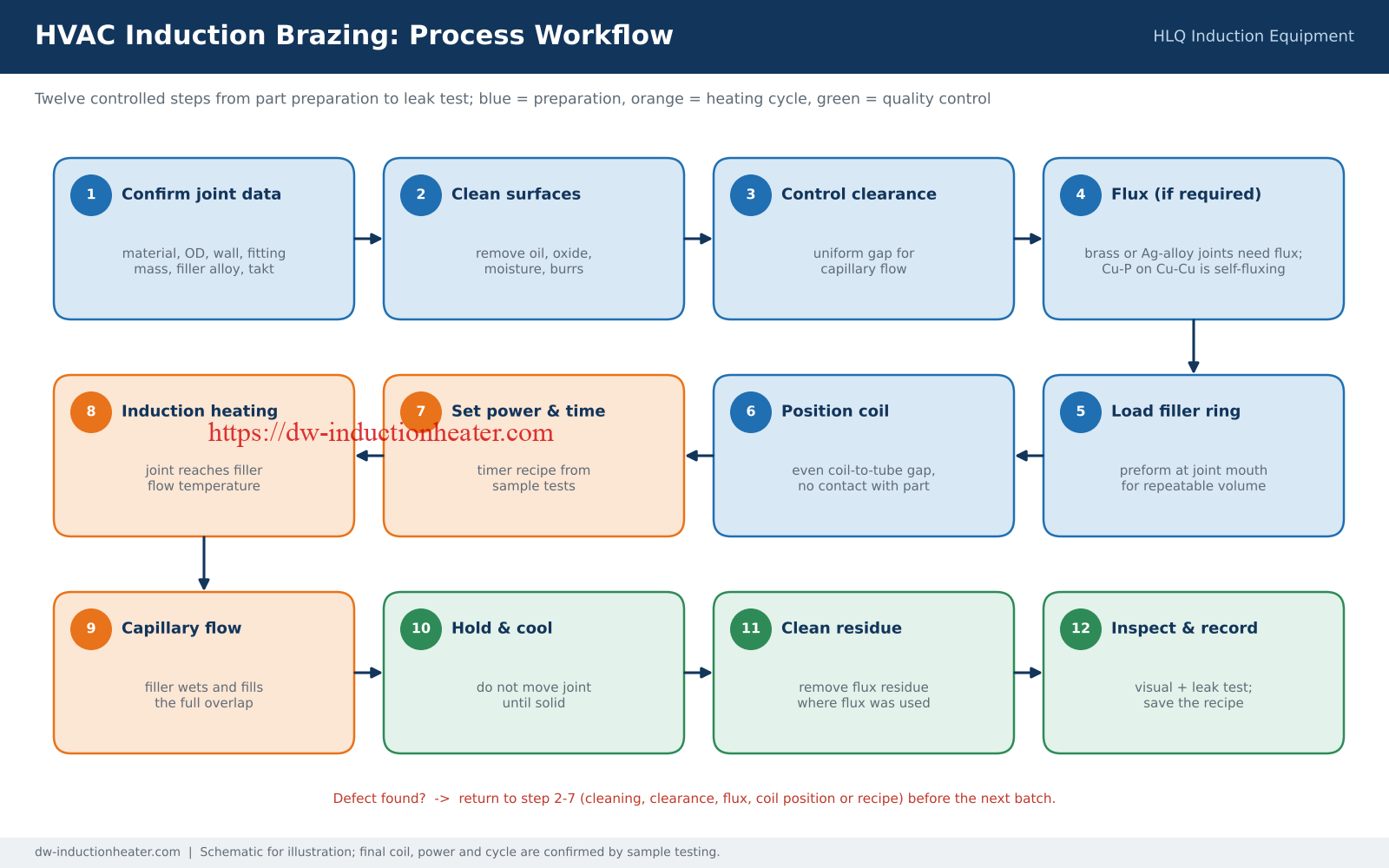
- Confirm joint data: tube material, OD, wall thickness, fitting material and mass, filler alloy and target cycle time.
- Clean surfaces: remove oil, oxide, dust and moisture from the tube end and fitting socket.
- Control clearance: keep a uniform gap, as recommended by the filler supplier, for capillary flow.
- Apply flux where required: brass and silver-alloy joints need flux; Cu-P filler on copper-to-copper is self-fluxing.
- Load the filler: place a preformed ring at the joint mouth for repeatable filler volume.
- Position coil and fixture: centre the joint with a uniform coil-to-part gap and no contact.
- Set power and time: use the timer recipe established in sample tests.
- Start induction heating: the joint heats to the filler flow temperature.
- Capillary flow: the filler wets the surfaces and fills the overlap.
- Hold and cool: do not move the joint before the filler solidifies.
- Clean flux residue: where flux was used.
- Inspect and record: visual check and leak test; save power, time and coil data.
| Process variable | Effect on brazing | Control method |
|---|---|---|
| Power | Heating speed | Set by joint mass and material |
| Frequency | Heating depth and coupling | Match to part size and coil design |
| Heating time | Filler flow and oxidation | Timer for repeatability |
| Coil distance | Heating uniformity | Fixture with consistent gap |
| Joint clearance | Capillary action | Tube sizing and fixture |
| Filler amount | Joint strength and appearance | Preformed rings for batch production |

Common Problems and Solutions
| Problem | Possible cause | Engineering solution |
|---|---|---|
| Filler does not flow into the joint | Temperature too low, poor cleaning, wrong filler or clearance too small | Increase power or time, clean the surfaces, verify filler melting range and adjust clearance |
| Filler balls up at the mouth | Oxidation, poor flux, contamination or uneven heating | Improve cleaning, apply correct flux, adjust coil position |
| One part lags behind (often the heavier brass fitting) | Different mass and thermal behaviour of the two parts | Bias the coil toward the heavier part, change coil distance or redesign the coil |
| Uneven brazing around the tube | Coil not centred or joint gap not uniform | Redesign the coil, improve fixture and alignment |
| Joint turns black or overheats | Excessive power, long heating time, wrong flux or poor protection | Reduce heating time, use temperature feedback, correct flux or protective gas |
| Brass discoloration | Overheating causing zinc evaporation | Lower power or time and control temperature |
| Leak at leak test | Incomplete fill from poor wetting, contamination or movement during cooling | Optimize clearance and cleaning, hold the fixture until solid, verify filler compatibility |
| Coil overheats | Insufficient cooling water or blocked coil tube | Check water flow, pressure and water quality; clean the coil |
| Machine alarms frequently | Water shortage, overcurrent, overload or poor load matching | Check input power, cooling system and coil matching |
Engineering Selection Guide
1. Define the joint
Measure tube OD, wall thickness, overlap length and the mass of the fitting. Tube-to-tube, tube-to-fitting, distributor and compressor joints each need a different coil and power level.
2. Confirm the material combination
Mixed-metal joints need heat balance. Copper conducts heat away quickly, while brass and steel heat differently under the same coil, so the coil may need to concentrate more energy on one side.
3. Select filler and brazing temperature
The filler sets the process temperature. Cu-P and Cu-P-Ag are standard for copper; silver alloys with flux are used for copper to brass and copper to steel. HLQ’s documented copper HVAC examples run at approximately 700–800 °C.
4. Estimate power and frequency
In portable brazing, 10–25 kW covers many copper tube and HVAC applications, while 30–60 kW suits larger brass, steel and stainless assemblies. Small parts favour higher frequency; larger parts need more power and often lower frequency.
5. Design the coil and fixture
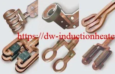
The coil decides the heating pattern. HLQ designs custom induction heating coils around the joint geometry and access: closed helical coils for 360° access, C-, U- or split coils for side access, and multi-tube coils for distributors.
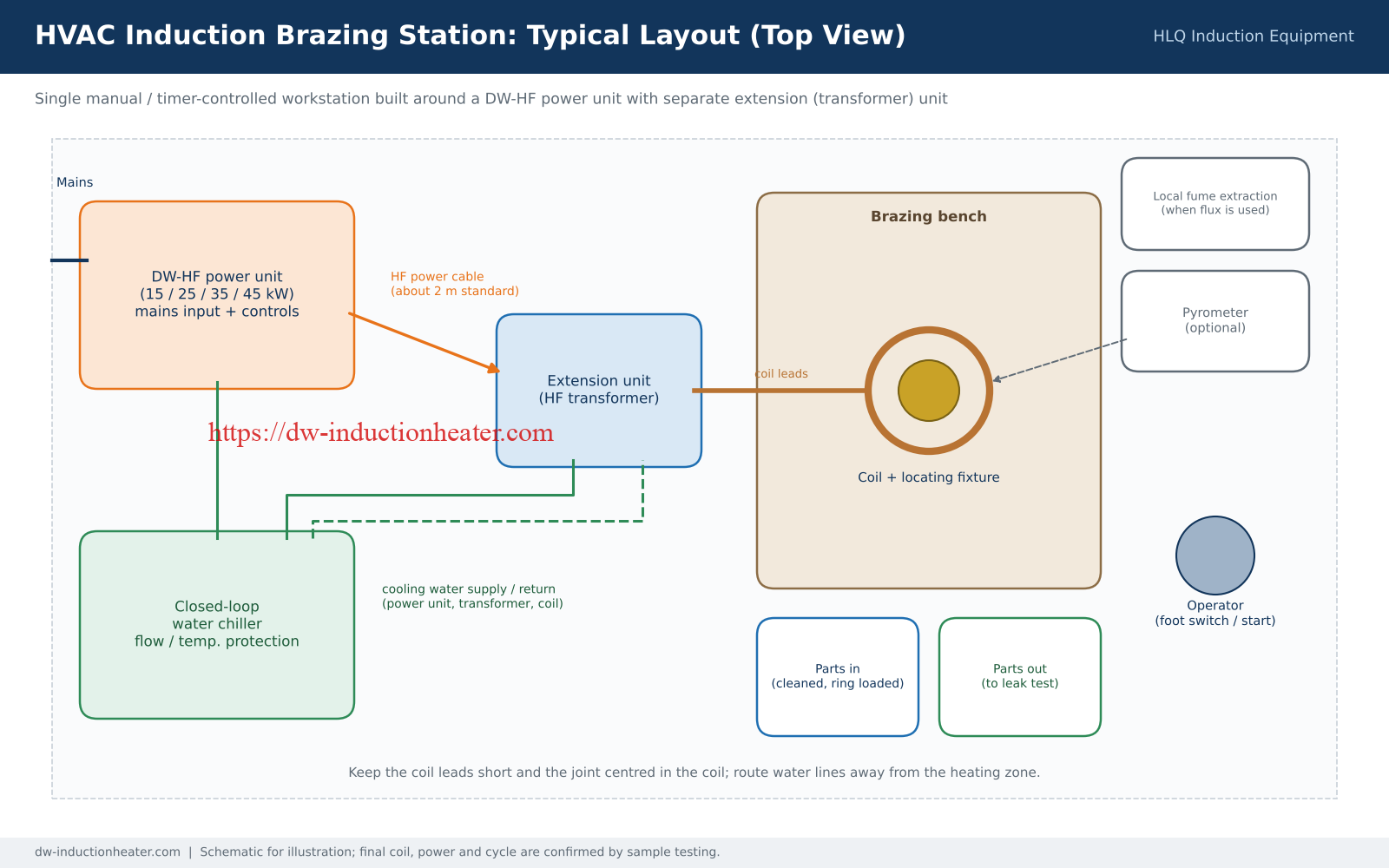
6. Plan electrical supply, cooling and layout
DW-HF-15kW runs on single-phase 220 V; the 25, 35 and 45 kW models need 3-phase 380 V. Continuous production needs a closed-loop chiller with water-flow protection.
7. Verify with sample tests
Before production, test real parts and record power, frequency, heating time, filler flow, appearance and leak-test result. These records become the production recipe.
| Information to provide HLQ | Example |
|---|---|
| Tube material | Copper / brass / steel / aluminium |
| Tube OD and wall thickness | mm or inch |
| Fitting material | Copper / brass / steel |
| Joint geometry | Tube-to-tube / tube-to-fitting |
| Brazing alloy | Cu-P / Cu-P-Ag / Ag-based alloy |
| Required heating time | Seconds |
| Production rate | Joints per hour |
| Operation | Manual / automatic |
| Coil access | 360° / side access |
| Electrical supply | Voltage / Hz / phase |
| Cooling conditions | Water chiller / cooling tower |
Advantages and Limitations
Advantages
| Advantage | Engineering value | Production value |
|---|---|---|
| No open flame | No combustion at the joint and no gas bottles at the station | Safer workshop near sensitive HVAC components |
| Localized heating | Heat concentrated in the joint area | Less distortion, discoloration and wasted energy |
| Repeatable cycle | Power and time set digitally | Stable joint quality, less dependence on torch skill |
| Fast heating | Heat generated inside the metal | Shorter cycle per joint |
| Less oxidation | Short heating time | Better appearance, less post-cleaning |
| Automation friendly | Integrates with PLC, fixtures and robots | Suitable for HVAC assembly lines |
| Flexible coils | One power supply, multiple coils | Covers several tube sizes and joint types |
For field and service work, a handheld induction heater keeps these benefits while bringing the coil to joints that cannot be moved to a bench. More background is in advantages of induction heating.
Induction brazing vs torch brazing for HVAC
| Item | Induction brazing | Torch brazing |
|---|---|---|
| Heat source | Electromagnetic induction | Combustion flame |
| Heat control | Digital power and time control | Manual flame adjustment |
| Repeatability | High with fixture and timer | Depends strongly on operator skill |
| Heating area | Localized | Wider heat-affected area |
| Safety | No open flame | Open flame and gas storage required |
| Automation | Easy to integrate | More difficult |
| Initial cost | Higher machine investment | Lower equipment cost |
| Best use | Repeatable industrial brazing | Simple repair or low-volume work |
Limitations
| Limitation | Explanation | Recommended action |
|---|---|---|
| Coil design required | Different joints often need different coils | Send samples or drawings before machine selection |
| Higher initial cost than a torch | Power supply, coil and cooling add investment | Evaluate total production cost and quality improvement |
| Access limits | Closed coils may not fit complex assemblies | Use U-shaped, split or custom profile coils |
| Aluminium is harder | Narrow temperature window and oxide layer | Precise control, correct flux and sample testing |
| Cooling water needed | Coil and transformer must be cooled | Industrial chiller with water-flow protection |
| Operator training | Cleaning, filler placement and coil position still matter | Standard operating procedures per joint |
Why Choose HLQ?
HLQ Induction Equipment manufactures induction heating machines from 5 kW to 2000 kW for brazing, hardening, melting, forging and PWHT, with custom systems shipped to more than 60 countries. For HVAC brazing projects, HLQ supports the whole process rather than only the power supply:
| HLQ capability | Customer benefit |
|---|---|
| DW-HF high frequency range from 15 kW to 45 kW and above | One supplier from small tube joints to multi-joint distributors |
| Custom induction coil design | Heating matched to copper-to-copper, copper-to-brass and distributor joints |
| Engineering selection support | Lower risk of choosing the wrong power or frequency |
| Manual, handheld, portable and automated configurations | Suits repair work, workshop production and assembly lines |
| Sample testing approach | Parameters proven on real parts before production |
| Export-oriented configuration | Voltage, language, cooling and safety design customized |
For copper, brass, carbide and HVAC work across one product line, see the induction brazing machine for copper, brass, carbide and HVAC brazing, and more application examples under induction brazing applications.
10 Core FAQs
1. Can induction heating braze copper HVAC pipes?
Yes. Induction heating is well suited to copper tube-to-tube and tube-to-fitting brazing. A properly designed coil heats the joint area rapidly while the filler flows through the joint by capillary action.
2. What temperature is needed to induction braze HVAC copper pipes?
It depends on the filler and base materials. Brazing uses a filler with a liquidus above 450 °C (840 °F); HLQ’s documented copper-pipe HVAC examples run at approximately 700–800 °C.
3. How long does induction brazing a copper pipe joint take?
HLQ’s documented examples range from about 5 seconds per joint in one heat-exchanger application to about 20 seconds in another copper-pipe application. Actual time depends on tube size, wall thickness, fitting mass, coil coupling, power and filler.
4. What power do I need for HVAC copper tube brazing?
Small copper tubes below 10 mm usually need 5–10 kW, HVAC tube joints of 10–25 mm need 10–25 kW, and distributors 15–35 kW. Larger distributors or multiple joints may need 40–60 kW.
5. Which HLQ model is best for HVAC brazing?
The DW-HF-15kW (single-phase 220 V) suits small tubes and workshops. The DW-HF-25kW and DW-HF-35kW cover most HVAC copper pipe, brass fitting and distributor joints, and the DW-HF-45kW handles brass-heavy fittings and faster cycles.
6. Which brazing alloy is used for copper HVAC tubing?
Copper-phosphorus and copper-phosphorus-silver fillers are common for copper-to-copper joints, with 15% silver the standard for refrigeration repair. Silver brazing alloys with flux are used for copper-to-brass and copper-to-steel joints.
7. Does induction brazing need flux?
Copper-phosphorus filler is self-fluxing on copper-to-copper joints. Brass, steel and silver-alloy joints need a suitable flux, and some stainless or sensitive parts use a protective atmosphere instead.
8. Which coil is used for HVAC pipe brazing?
C-shaped, U-shaped and helical coils are common, chosen by pipe diameter, joint geometry and access. Production lines use custom coils that heat one or several joints while limiting heat to surrounding components.
9. Is induction better than torch brazing for HVAC production?
For repeatable production, induction gives programmable heating time and power, localized heat, no open flame and easy automation. Torch brazing can still suit low-volume repair where flexibility and low equipment cost matter most.
10. Does an induction brazing machine need cooling water?
Yes. The coil, extension unit and power components are water-cooled. The DW-HF-35kW and DW-HF-45kW require at least 6 L/min at no more than 0.3 MPa, and a closed-loop chiller is recommended for continuous work.