
Induction Straightening vs Induction Bending for Steel Fabrication
Table of Contents
- Quick Answer
- Comparison Overview
- Working Principle Comparison
- Key Technical Parameters
- Efficiency and Energy Cost Comparison
- Temperature Control Comparison
- Material Quality and Surface Condition
- Safety and Compliance Comparison
- Maintenance Comparison
- Total Cost of Ownership
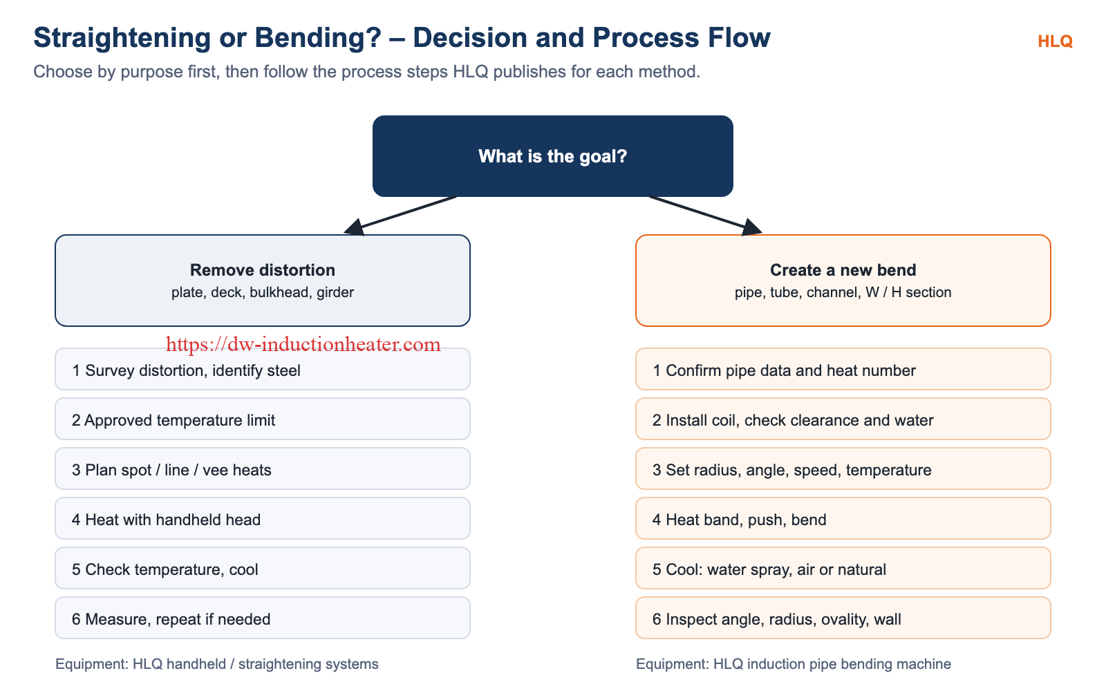
- Engineering Selection Guide
- Common Engineering Mistakes
- Common Problems and Solutions
- Real Project Case Study
- Honest Limitations of Both Methods
- Final Recommendation
- FAQ
Induction straightening and induction bending both use electromagnetic induction to heat steel locally. Otherwise they are different processes with opposite goals. Straightening removes unwanted distortion from plates, decks, bulkheads and girders, while bending forms a planned curve in pipes, tubes and structural sections. This guide compares the two on temperature, forming force, equipment, energy, quality checks, safety, cost and standards. It is written for shipyards, bridge and steel-structure contractors, pipe fabricators and purchasing engineers who need to know which process and equipment their job actually requires.
Quick Answer
Choose induction straightening when a part has already been distorted, for example by welding or impact, and must be brought back to its design shape. The steel is heated locally and kept below its approved limit; for bridge carbon steels, provisions citing FHWA guidance set 1200 °F (about 650 °C). Choose induction bending when a pipe, tube or section must be formed into a new radius and angle. A narrow 360° band of the pipe is heated to forming temperature (800–1080 °C for carbon steel pipe in HLQ data) while the pipe is pushed through the coil and bent. The two processes are not interchangeable, and many shipyards and fabricators need both.
Comparison Overview
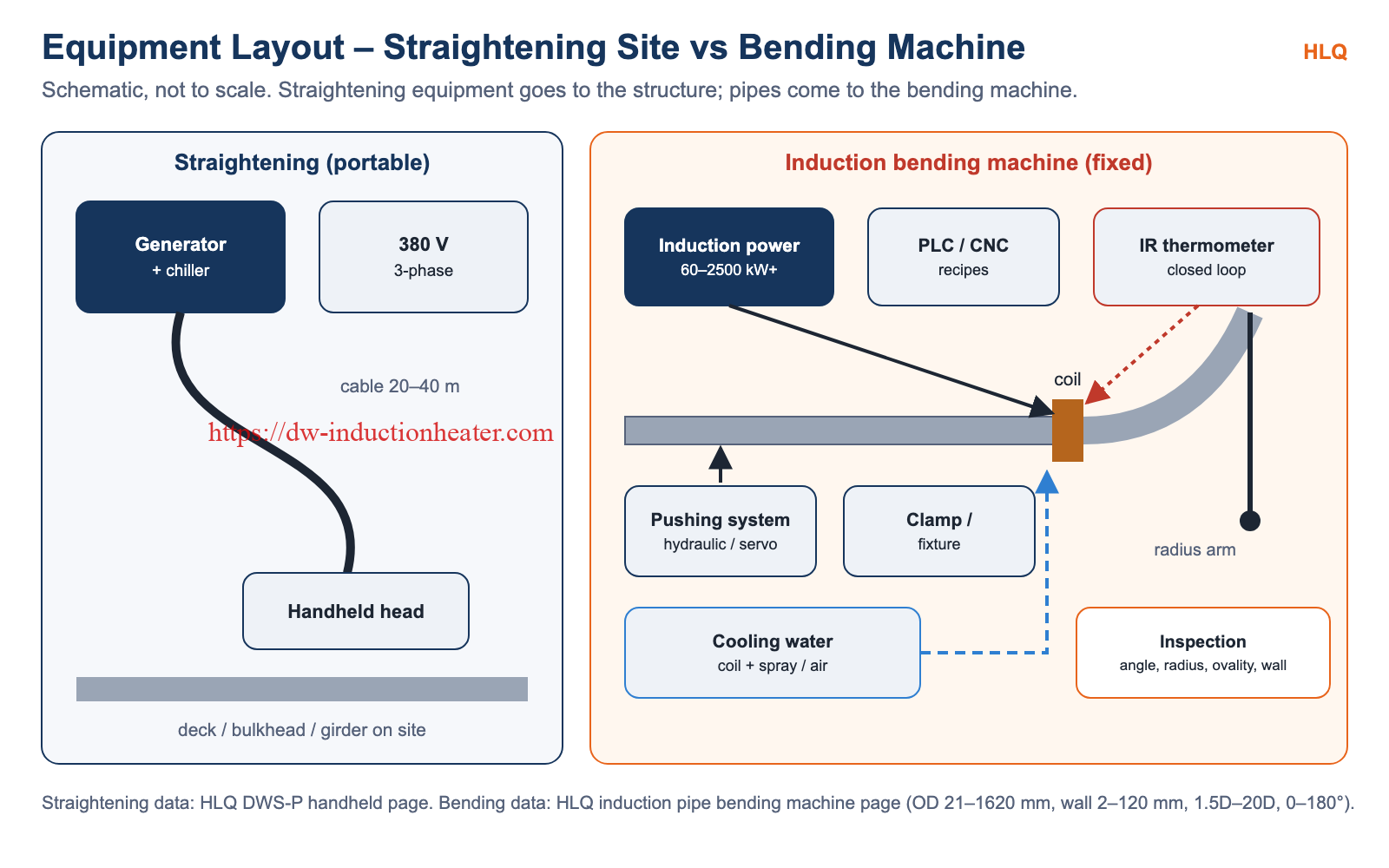
Induction straightening is a correction process. Welding and cutting distort thin decks, bulkheads and stiffened panels, and girders can be bent by fabrication or impact. A portable induction heating head applies local heats in a planned pattern, and the steel straightens as the heated zones cool and contract. Equipment ranges from handheld remote induction heaters to larger induction straightening heating machines.
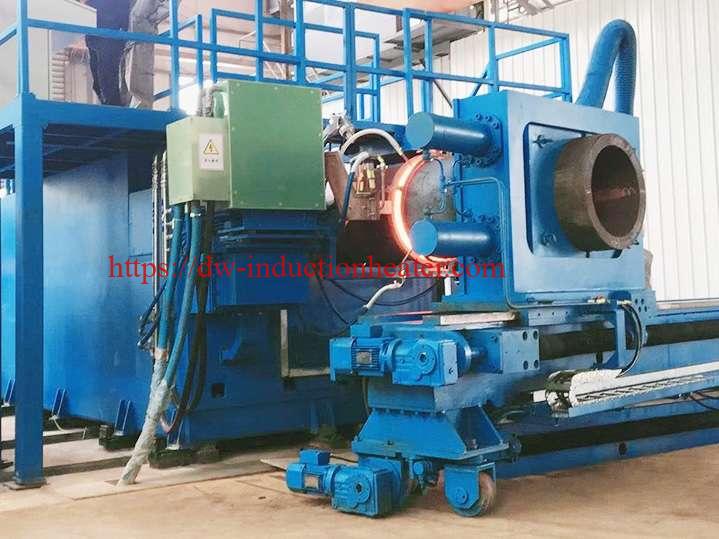
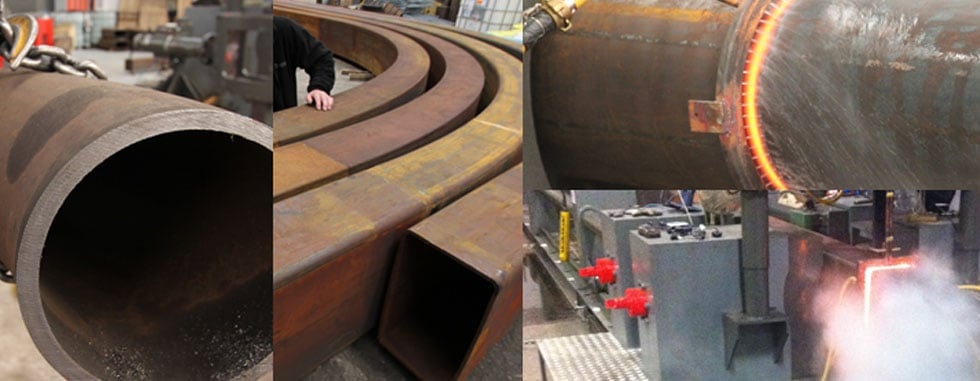
Induction bending is a forming process. A machine clamps the pipe, heats a narrow ring with a coil, pushes the pipe forward and bends the hot band with a radius arm or rolls. This produces custom long-radius bends that replace welded elbows. HLQ supplies this as the induction pipe bending machine.
Working Principle Comparison
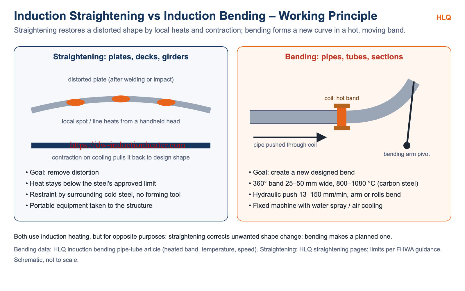
Straightening works in three steps:
- A heated spot or line tries to expand.
- The cold steel around it restrains that expansion, so the hot zone thickens (upsets) instead.
- On cooling, the zone contracts and shortens, pulling the distorted plate or member back toward its design shape.
No forming tool is needed; restraint comes from the structure itself. Spot, line and vee heating patterns decide where the shortening happens.
Bending also works in steps:
- A solenoid coil around the pipe heats a 360° band, usually 25–50 mm (1–2 in) wide for carbon steel pipe.
- Once the band is ductile, the pipe is pushed through the coil at a controlled speed of 13–150 mm/min.
- The leading end, clamped to a pivoting bending arm (or held between rolls for larger radii), bends within the hot band. The cold, non-ductile pipe on each side of the band supports it.
- The bend is cooled by water spray, forced air or natural cooling, and can then be stress relieved or tempered to obtain the required post-bend properties.
More detail: induction bending pipe and tube.
Key Technical Parameters
| Parameter | Induction Straightening | Induction Bending | Engineering Impact |
|---|---|---|---|
| Purpose | Remove distortion and restore design shape | Create a new designed bend | Decides which process applies |
| Typical workpieces | Plates, decks, bulkheads, frames, girders, beams | Pipes, tubes, channels, W and H sections | Different tooling and machines |
| Heating zone | Local spots, lines or vees | 360° band, 25–50 mm wide (carbon steel pipe) | Coil type: flat heating head vs solenoid coil |
| Steel temperature | Below the approved limit (bridge carbon steels: 1200 °F ≈ 650 °C) | 800–1080 °C for carbon steel pipe (HLQ data) | Straightening limits must never be set to bending temperatures |
| Forming force | Restraint of surrounding cold steel; limited external jacking | Hydraulic or servo-hydraulic push; bending arm or rolls | Bending needs a rigid machine bed |
| Speed | Seconds to minutes per heat (HLQ ship reference: 30–210 s) | 13–150 mm/min pushing speed | Different productivity metrics: m² vs bends per shift |
| Power | 25–60 kW handheld (DWS-P); 25–300 kW systems | 60–2500 kW+ | Bending power scales with pipe OD and wall thickness |
| Frequency | 20–50 kHz (DWS-P handheld); 0.5–15 kHz (straightening systems) | 0.5–30 kHz typical; lower for larger and thicker pipe | Heating depth and coupling |
| Size range | Steel thickness up to 15 / 30 / 60 mm by system size | Pipe OD 21–1620 mm, wall 2–120 mm, radius 1.5D–20D, angle 0–180° | Defines machine selection |
| Mobility | Portable; head on 20–40 m remote cable | Fixed machine; pipes brought to it | Site work vs shop work |
| Cooling of workpiece | Heated zone cools before the next heat | Water spray, air or natural, by material | Affects properties after bending |
| Key standards | FHWA heat-straightening guidance (bridges); IACS Rec. 47 (ships) | ASME B16.49; ISO 15590-1 (pipeline induction bends) | Different acceptance criteria |
Efficiency and Energy Cost Comparison
Both processes heat only a limited zone rather than the whole part, which is the main energy advantage of induction in each case. In bending, rapid circumferential heating of the bending zone uses less energy than hot bending methods that heat the entire pipe.
The energy figures are not comparable between the two processes, because the jobs differ:
- Straightening: HLQ publishes an idealized example for its handheld units. Assuming 50% utilization and 40% coupling, it gives about 9.7 m²/h for the DWS-25P, 11.7 m²/h for the DWS-30P and 23.4 m²/h for the DWS-60P. These are calculated values, not measured straightening rates.
- Bending: power is sized by pipe size and production speed:
| Pipe OD | Wall thickness | Typical power | HLQ machine type |
|---|---|---|---|
| 21–89 mm | 2–12 mm | 60–160 kW | Small tube induction bending machine |
| 89–219 mm | 4–25 mm | 160–300 kW | Medium pipe induction bending machine |
| 219–426 mm | 6–40 mm | 300–600 kW | Heavy-duty pipe bending system |
| 426–720 mm | 8–60 mm | 600–1000 kW | Large pipe induction bending machine |
| 720–1020 mm | 10–80 mm | 1000–1600 kW | Large-diameter pipeline bending system |
| 1020–1620 mm+ | 12–120 mm | 1600–2500 kW+ | Customized heavy-duty induction bending line |
Temperature Control Comparison
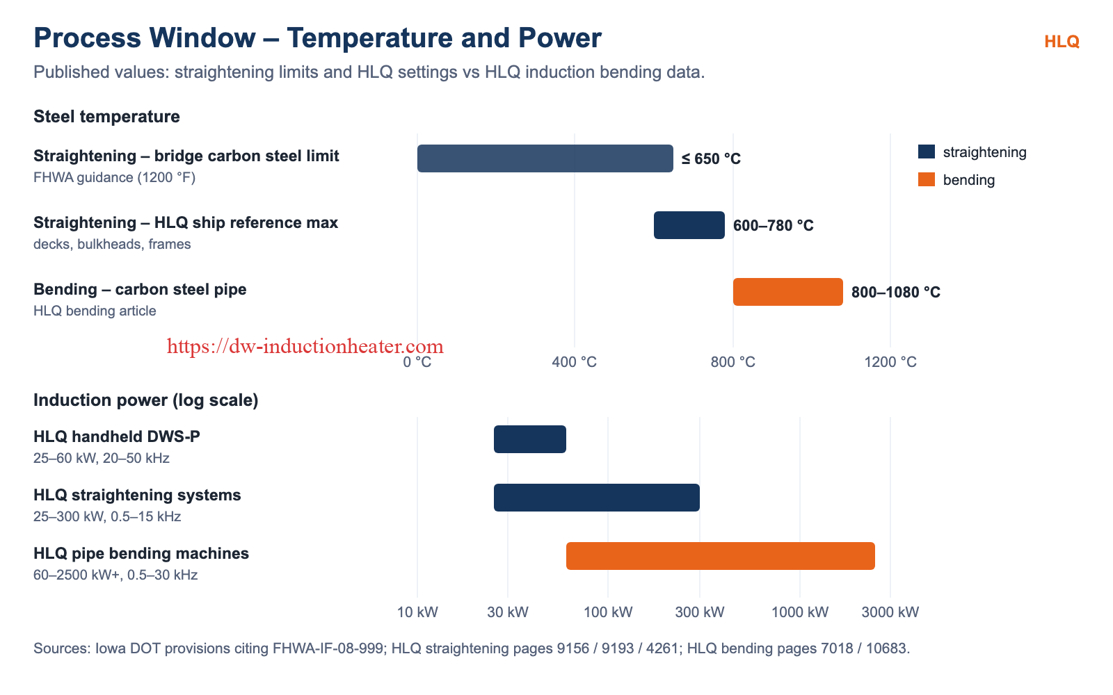
Straightening works under a maximum temperature. Iowa DOT provisions citing FHWA-IF-08-999 set these limits for bridge steels:
- Carbon steels: 1200 °F (≈ 650 °C).
- A514 and A709 Grades 100/100W: 1100 °F (≈ 593 °C).
- A709 Grade 70W: 1050 °F (≈ 566 °C).
For ships, IACS Recommendation 47 contains a line-heating temperature provision that must be confirmed with the classification society. The operator verifies each heat with temperature-indicating crayons or a calibrated pyrometer.
Bending works within a forming window: the band must be hot enough to be ductile (800–1080 °C for carbon steel pipe in HLQ data) and even around the circumference. HLQ bending machines use an infrared thermometer with closed-loop control, and the target temperature is set together with the radius, angle, speed and cooling mode.
Material Quality and Surface Condition
- Straightening: within the approved limit, the main quality risk is overheating. Temperatures above about 700 °C begin to approach the lower critical temperature of steel, according to a TAC paper on the FHWA guidance. Coatings over the heated zones should be expected to need repair.
- Bending: some wall thinning normally occurs on the outer arc of the bend. A correct process keeps thinning, ovality, wrinkles and cracking within the project’s limits. A small radius increases deformation, wall thinning and ovality. Material notes from HLQ:
- Stainless steel needs accurate temperature control to reduce oxidation and distortion.
- Duplex stainless needs a strict thermal procedure.
- Low-temperature steels may need impact property verification after bending.

Safety and Compliance Comparison
| Topic | Induction Straightening | Induction Bending |
|---|---|---|
| Electrical | Generator, remote cable and handheld head near the operator | High-power supply (up to 2500 kW+) in a fixed installation |
| Mechanical | Limited; restraint and any jacking forces must stay within approved limits | High pushing forces, moving radius arm, clamps and heavy pipe |
| Hot material | Local hot spots on large structures | A long, hot pipe bend that must be cooled and handled |
| Cooling water | Generator and head cooling (DWS-P: ≥ 0.5 MPa, ≥ 30 L/min) | Coil cooling with flow switch, plus spray cooling of the bend |
| Common standard | IEC 60519 series for electroheating installations | IEC 60519 series; bends to ASME B16.49 / ISO 15590-1 where applicable |
Both processes avoid open flames. For a direct comparison of straightening methods, see induction straightening vs flame straightening.
Maintenance Comparison
- Straightening equipment:
- Cooling water quality, pressure and flow.
- Remote cable and heating head inspection.
- Pyrometer calibration and emissivity checks.
- Working within the published duty cycle (50% for DWS-P).
- Bending machines:
- Coil condition: correct clearance, water flow with flow switch and temperature monitoring, and heat- and water-resistant insulation.
- Hydraulic or servo pushing system.
- Clamps and radius arm alignment.
- Infrared thermometer calibration.
Total Cost of Ownership
The two investments are on different scales and solve different problems:
- Straightening: a portable 25–60 kW handheld system, or a 25–300 kW system for thicker steel. The return comes from corrected distortion: labour time, repeat heats and rework.
- Bending: a fixed 60–2500 kW+ machine with a pushing system, radius arm and controls. The return comes from custom long-radius bends that replace multiple standard elbows and welds, and from fewer joints to weld and inspect.
Compare each against its real alternative: flame or mechanical straightening for distortion, and purchased elbows or cold bending for pipe routing.
Engineering Selection Guide
| Condition | Recommended Option | Reason |
|---|---|---|
| Welding distortion in ship decks and bulkheads | Induction straightening | Local heats restore flatness; portable equipment on deck |
| Bent bridge girder flange after impact | Induction straightening (within FHWA limits) | Corrects shape without replacing steel |
| Long-radius pipeline or process pipe bends | Induction bending | Custom radius 1.5D–20D, fewer elbows and welds |
| Thick-wall or large-diameter pipe | Induction bending | Up to 1620 mm OD and 120 mm wall with suitable machines |
| Marine pipe systems in a shipyard | Induction bending | HLQ lists shipbuilding pipe bending at 200–500 kW, 2–10 kHz |
| Curved structural tubes or sections | Induction bending | Pipes, channels and W/H sections can be bent |
| A previously bent pipe that is slightly out of tolerance | Engineering review first | Re-heating an induction bend affects its properties; check the bend standard |
Common Engineering Mistakes
- Expecting a straightening head to form bends: forming needs a coil around the pipe, a pushing system and a bending arm or rolls.
- Using bending temperatures for straightening: 800–1080 °C is far above straightening limits such as 1200 °F (≈ 650 °C) for bridge carbon steels.
- Choosing too small a bend radius: this increases wall thinning and ovality.
- Ignoring the inspection standard: bends may need wall thickness, ovality, hardness, NDT, mechanical tests or post-bend heat treatment.
- Undersizing power: bending power must match pipe OD, wall thickness and speed; straightening power must match plate thickness.
- Skipping trials: both processes need settings confirmed on the actual material and geometry.
Common Problems and Solutions
| Problem | Process | Solution |
|---|---|---|
| Over-correction or little effect | Straightening | Review the heating pattern; measure after each heat |
| Temperature above the limit | Straightening | Reduce power or time; verify every heat |
| Ovality or wrinkling | Bending | Check fixture and clamping, radius and temperature uniformity |
| Excessive wall thinning on the outer arc | Bending | Larger radius; correct temperature, speed and cooling |
| Inaccurate bend angle | Bending | Stable pushing speed; prevent pipe slipping in the clamp |
| Coil overheating | Both | Check water flow, flow switch and coil clearance |
Real Project Case Study
HLQ publishes reference data for both processes, intended as starting points to be confirmed by trials on the actual material.
Straightening: reference settings for ship structures (induction straightening of bulkheads and decks):
| Application | Thickness (mm) | Power (kW) | Heating time (s) | Max. temperature (°C) |
|---|---|---|---|---|
| Deck plate | 8 | 40 | 45–60 | 650 |
| Deck plate | 12 | 60 | 70–90 | 700 |
| Bulkhead | 10 | 50 | 60–75 | 680 |
| Frame / stiffener | 6 | 30 | 30–45 | 600 |
The settings above 650 °C are shipbuilding values. They must not be used for bridge members and must be checked against the classification society’s limit.
Bending: recommended power and frequency by application:
| Application | Material | Power | Frequency |
|---|---|---|---|
| Small boiler tube bending | Carbon / alloy steel | 60–160 kW | 10–30 kHz |
| Shipbuilding pipe bending | Carbon / stainless steel | 200–500 kW | 2–10 kHz |
| Power plant steam pipe bending | Alloy / heat-resistant steel | 500–1200 kW | 0.8–5 kHz |
| Oil and gas pipeline bending | Pipeline steel | 800–1800 kW | 0.5–3 kHz |
Customer-specific measurements, such as distortion before and after straightening or ovality and thinning of produced bends, are available on request for qualified projects.
Honest Limitations of Both Methods
- Induction straightening:
- Corrects shape but cannot create new geometry.
- Limited by the steel’s maximum temperature.
- Needs a reasonably flat surface for the heating head, plus power and cooling water on site.
- Handheld units have a 50% published duty cycle and limited heat for very thick members.
- Induction bending:
- Needs a large, fixed machine and pipes brought to it.
- Some wall thinning on the outer arc is normal.
- Small radii increase ovality.
- Some materials need strict procedures or post-bend testing and heat treatment.
- The investment grows quickly with pipe size.
Final Recommendation
- Distortion that must be removed, as in decks, bulkheads, girders and frames: use induction straightening within the approved temperature limit, with a heating plan and measurement after each heat.
- A new curve in a pipe, tube or section: use induction bending, with the radius, angle, temperature, speed and cooling set for the material and the applicable bend standard.
Shipyards and fabricators that do both kinds of work usually need both kinds of equipment, because one cannot replace the other.
FAQ
What is the main difference between induction straightening and induction bending?
Straightening removes unwanted distortion; bending creates a planned curve. They use different temperatures, forces and equipment.
Can a straightening system bend pipes?
No. Bending needs a coil around the pipe, a pushing system and a bending arm or rolls.
What temperature is used for induction bending?
For carbon steel pipe, HLQ data gives a bending temperature range of 800–1080 °C in a 25–50 mm wide heated band.
What is the temperature limit for straightening?
It depends on the steel. For bridge carbon steels, provisions citing FHWA guidance set 1200 °F (≈ 650 °C), and quenched and tempered grades have lower limits.
Which standards cover induction bends?
ASME B16.49 for factory-made carbon steel pipeline induction bends, and ISO 15590-1 for induction bends in petroleum and natural gas pipeline systems.
What is inspected after induction bending?
Bend angle, radius, ovality, wall thinning, surface cracks, and hardness and material properties where required.
What bend radius can induction bending produce?
HLQ machines produce bends from 1.5D to 20D at angles of 0–180°, depending on the model.
Does a shipyard need both processes?
Often yes: straightening for welded decks and bulkheads, and bending for marine pipe systems.
HLQ-Induction-Straightening-vs-Induction-Bending