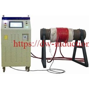


Induction Preheat Welding Machine
Induction Preheat Welding Machine for Pipeline Welding and Industrial Heat Treatment
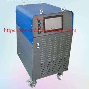
The HLQ Induction Preheat Welding Machine is an industrial electromagnetic heating system designed for controlled preheating of steel pipes, welded joints, fabricated metal structures and selected pressure components.
The MYD series includes six published models: MYD-40, MYD-50, MYD-60, MYD-80, MYD-100 and MYD-120, providing nominal output power ratings from 40 kW to 120 kW.
The system combines IGBT induction power conversion, flexible induction heating coils, PLC touchscreen control and multi-point temperature monitoring to support industrial welding preparation and selected controlled heating processes.
The published output frequency range for this product series is 2–36 kHz. Standard input voltage is listed as three-phase 380 V, with three-phase 220 V and 440 V configurations described as optional.
Typical applications include oil and gas pipeline welding, steel pipe fabrication, industrial weld repair, localized preheating, interpass temperature management and selected post-weld thermal treatment operations.
Actual heating performance depends on the workpiece material, diameter, wall thickness, heating-zone width, target temperature, heating time, thermal insulation and verified useful heating power.
Quick Answer
What Is an Induction Preheat Welding Machine?
An induction preheat welding machine is an industrial heating system that uses electromagnetic induction to generate controlled heat inside electrically conductive metal before welding begins.
High-frequency alternating current flows through an induction heating coil, generating a changing magnetic field around the workpiece. The magnetic field induces electrical currents in the metal, producing heat through electrical resistance.
The HLQ MYD series provides six published nominal power ratings from 40 kW to 120 kW, with an output frequency range of 2–36 kHz.
Main applications: Industrial welding preheating, pipeline welding, pipe joint heating, selected postheating operations and controlled heating of large steel components.
Control features: IGBT induction power conversion, PLC touchscreen operation, flexible heating coils and published multi-point temperature-monitoring capabilities.
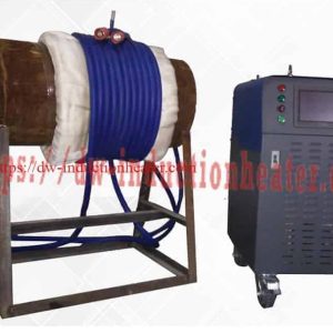
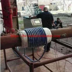
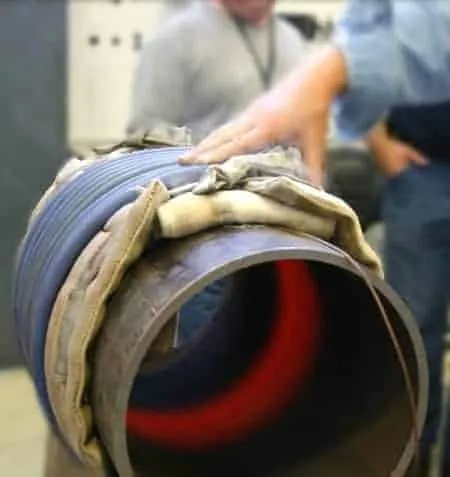
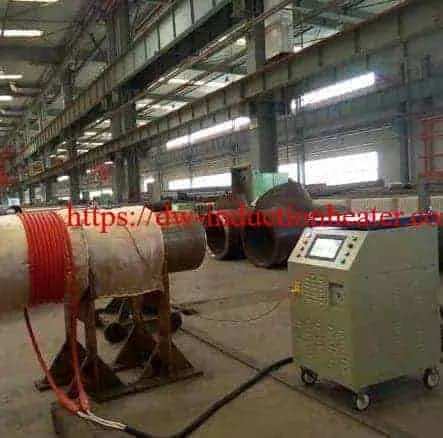
Correct pipe installation: Place thermocouples directly against the steel pipe, cover the sensors and pipe with thermal insulation blankets, secure the blankets using non-metallic insulating straps, and wind the induction heating cable around the outside of the insulation.
Engineering requirement: Equipment power must be selected from the workpiece thermal load and required heating cycle rather than pipe diameter alone.
MYD Series at a Glance
| Model | Nominal Output | Published Input Current | Published Machine Weight |
|---|---|---|---|
| MYD-40 | 40 kW | 60 A | 130 kg |
| MYD-50 | 50 kW | 75 A | 136 kg |
| MYD-60 | 60 kW | 90 A | 140 kg |
| MYD-80 | 80 kW | 120 A | 145 kg |
| MYD-100 | 100 kW | 150 A | 168 kg |
| MYD-120 | 120 kW | 180 A | 180 kg |
The input-current values above are historical manufacturer-published figures and require verification against the rated output, power factor, conversion efficiency and continuous operating conditions.
Table of Contents
- What Is an Induction Preheat Welding Machine?
- Key Applications
- Suitable Materials
- Working Principle
- Technical Specifications
- Recommended Model Selection
- Process Workflow
- Common Problems and Solutions
- Engineering Selection Guide
- Advantages and Limitations
- Why Choose HLQ?
- 10 Core FAQs
What Is an Induction Preheat Welding Machine?
An induction preheat welding machine is an electrically powered industrial heating system designed to raise the temperature of selected metal regions before welding.
Many welding procedures require a specified minimum base-metal temperature to control welding conditions and reduce the risk of certain cracking mechanisms.
For suitable steels, preheating can influence weld cooling rates and help manage conditions associated with hydrogen-assisted cracking.
The required preheat temperature depends on material composition, section thickness, restraint, welding process, consumables and the applicable welding procedure specification (WPS).
Unlike conventional flame heating, induction heating generates heat within the conductive metal through electromagnetic effects.
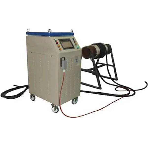
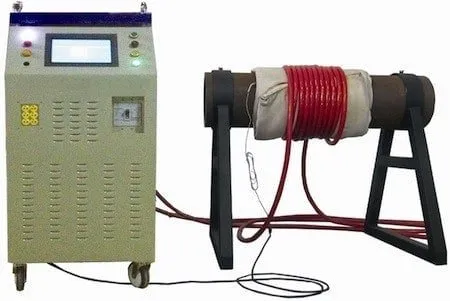
The MYD series uses an industrial induction generator connected to an appropriately matched flexible heating coil.
Main Equipment Components
| Component | Main Function | Engineering Consideration |
|---|---|---|
| IGBT Induction Generator | Converts electrical input into high-frequency induction power. | Rated output, frequency, load matching and continuous duty. |
| PLC Touchscreen | Provides the operator interface for supported heating functions. | Control functions and software configuration. |
| Flexible Induction Heating Coil | Generates an alternating magnetic field around the metal workpiece. | Cable construction, number of turns and electrical matching. |
| Clamp-Type Induction Coil | Provides an alternative workpiece heating arrangement. | Coil geometry and application compatibility. |
| K-Type Thermocouple | Measures workpiece temperature. | Direct metal contact and calibration. |
| Temperature Control System | Monitors and regulates supported temperature functions. | Number of channels and control accuracy. |
| Temperature Recorder | Records heating temperature data when included. | Channel count, storage and traceability. |
| Thermal Insulation Blanket | Reduces heat loss from the workpiece. | Temperature rating, thickness and coverage. |
| Non-Metallic Insulating Straps | Secure insulation and the heating cable. | Electrical insulation and high-temperature resistance. |
| Cooling System | Removes heat from designated generator or coil components. | Model-specific cooling requirements. |
Industrial MYD Series Versus Portable MYD Equipment
The MYD-40 through MYD-120 models are larger industrial systems than the compact 10 kW and 20 kW portable MYD machines.
The higher nominal power ratings can make these models candidates for more demanding heating applications, including larger pipe joints, wider heating bands and higher thermal loads.
However, a higher generator rating does not automatically guarantee a particular heating rate or temperature uniformity.
Actual processing capability must be verified for the selected workpiece and heating configuration.
Key Applications
1. Industrial Pipeline Welding Preheating
Pipeline welding preheating involves raising the temperature of the metal near a weld joint before welding begins.
Induction heating can be used to prepare suitable steel pipeline sections where a qualified welding procedure specifies minimum preheat temperatures.
Typical applications include oil and gas pipelines, process piping and industrial steel pipe fabrication.
For pipe-specific equipment selection, see the HLQ induction pipeline preheating machine engineering guide.
2. Oil and Gas Pipeline Construction
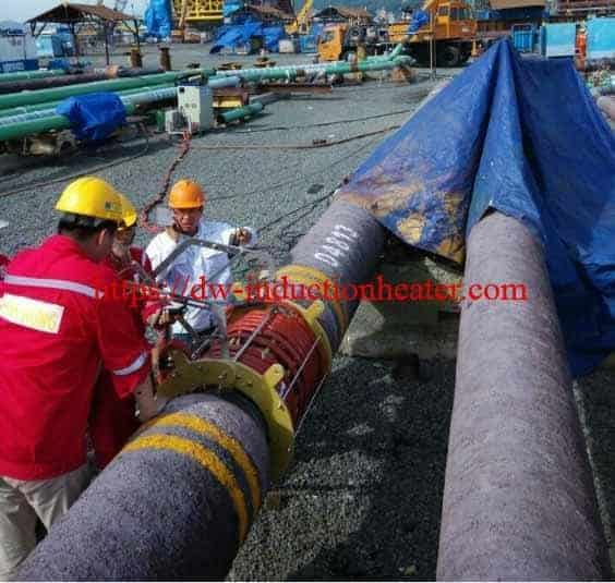
Oil and gas pipeline welding may require controlled preheating depending on material grade, wall thickness and welding requirements.
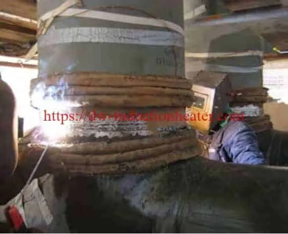
Flexible induction coils can be positioned around suitable pipe joints to provide electromagnetic heating of the conductive pipe wall.
Field operations require appropriate electrical power, safety procedures, temperature measurement and worksite preparation.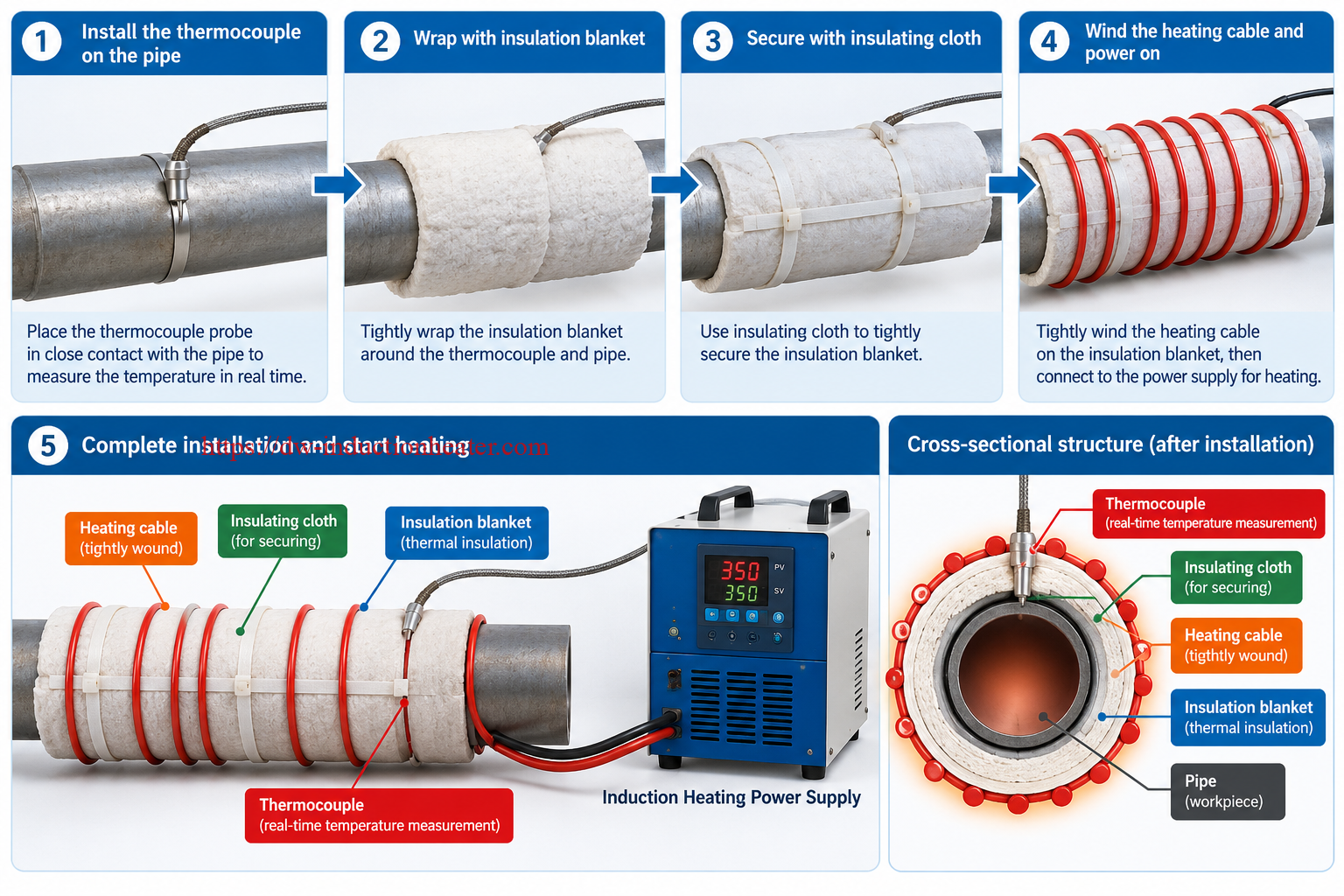
3. Industrial Pipe Fabrication
Fabricated steel pipes, elbows, flanges and pipe fittings may require localized heating before welding or assembly.
Induction heating may be suitable when the workpiece geometry allows a compatible coil arrangement and the required heating cycle is within the equipment capability.
4. Structural Steel Welding
Some structural steel welding procedures require preheating to a defined temperature.
The induction heating arrangement must be selected for the relevant plate thickness, weld geometry and heating area.
For non-cylindrical workpieces, specialized induction coil configurations may be necessary.
5. Weld Repair and Maintenance
Qualified repair procedures may require heating before welding begins.
Induction equipment can be evaluated for industrial maintenance operations involving accessible steel components.
For installed pipelines and pressure-containing systems, confirm that heating is permitted and that operating fluids, residual pressure and combustible materials have been addressed.
6. Localized Postheating
Some welding procedures require controlled heating or temperature holding after welding.
The specified temperature and holding duration depend on the material and the applicable process requirements.
Localized postheating should not automatically be described as formal PWHT.
7. Selected Post-Weld Heat Treatment Applications
Formal post-weld heat treatment may require controlled heating rates, prescribed soaking temperatures, holding periods, controlled cooling and temperature recording.
An induction heater can form part of a qualified PWHT system when the power supply, coil, monitoring and control arrangements are suitable.
Compliance depends on the applicable code and approved thermal procedure, not simply on the generator power rating.
Application Overview
| Application | Heating Objective | Critical Requirement |
|---|---|---|
| Pipeline Welding Preheat | Reach the specified temperature before welding. | WPS and pipe geometry. |
| Steel Pipe Fabrication | Provide localized metal heating. | Heating band and coil configuration. |
| Industrial Weld Repair | Condition the weld region before repair. | Qualified repair procedure. |
| Structural Steel Welding | Control pre-weld temperature. | Material grade and section thickness. |
| Interpass Temperature Management | Manage weld temperature between passes. | Approved temperature limits. |
| Postheating | Maintain a prescribed post-weld temperature. | Holding temperature and duration. |
| Formal PWHT | Apply a qualified post-weld thermal cycle. | Heating and cooling rates, soaking and records. |
Suitable Materials
Electromagnetic induction heating is applicable to electrically conductive materials.
Heating performance depends on magnetic permeability, electrical resistivity, thermal conductivity, heat capacity and the geometry of the workpiece.
Carbon steels are common materials for industrial induction welding preheating, but the correct temperature must always follow the relevant welding procedure.
Material Compatibility Table
| Material | General Suitability | Important Consideration |
|---|---|---|
| Low-Carbon Steel | Generally Suitable | Common welding preheat applications. |
| Structural Carbon Steel | Generally Suitable | Follow applicable WPS requirements. |
| Carbon Steel Pipeline | Generally Suitable | Diameter, wall thickness and heating band. |
| Low-Alloy Steel | Application-Dependent | Material-specific preheat requirements. |
| Cr-Mo Alloy Steel | Conditional | Potentially strict preheat and PWHT requirements. |
| High-Strength Steel | Conditional | Excessive temperature can alter properties. |
| Austenitic Stainless Steel | Requires Evaluation | Electromagnetic coupling differs from carbon steel. |
| Ferritic Stainless Steel | Requires Evaluation | Magnetic characteristics vary with grade and temperature. |
| Cast Iron | Conditional | Thermal gradients and cracking risks. |
| Aluminum | Specialized Application | Requires appropriate induction matching. |
| Copper | Specialized Application | High conductivity influences heating performance. |
Material Properties Affecting Heating
| Property | Effect on Induction Heating |
|---|---|
| Electrical Resistivity | Influences resistive power dissipation inside the metal. |
| Magnetic Permeability | Affects electromagnetic coupling and current penetration. |
| Thermal Conductivity | Controls heat spreading through the workpiece. |
| Specific Heat Capacity | Determines required sensible heating energy. |
| Workpiece Thickness | Influences thermal mass and through-wall temperature distribution. |
| Initial Temperature | Determines the required temperature increase. |
| Heat Treatment Condition | May restrict maximum permissible heating temperature. |
Working Principle
How Does an Induction Preheat Welding Machine Work?
The induction generator converts three-phase electrical input power into high-frequency alternating electrical energy.
This energy is delivered to an induction heating coil positioned around or near the conductive workpiece.
The alternating coil current generates a changing magnetic field.
The magnetic field induces electrical currents inside the metal.
Electrical resistance converts the induced electrical energy into heat within the workpiece.
Heat then spreads through the metal by thermal conduction.
Thermocouples installed directly against the steel surface provide temperature readings for monitoring and available control functions.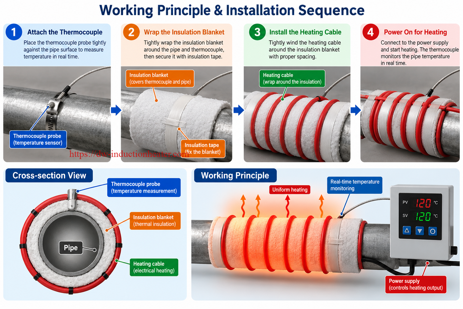
Electromagnetic Induction Heating Sequence
| Stage | Operation | Technical Result |
|---|---|---|
| 1 | Three-Phase AC Input | Electrical power enters the induction generator. |
| 2 | IGBT Power Conversion | The generator produces high-frequency power. |
| 3 | Induction Coil Energization | Alternating current creates a magnetic field. |
| 4 | Eddy Current Generation | Electrical currents develop within the workpiece. |
| 5 | Resistive Heating | Electrical losses generate heat inside the metal. |
| 6 | Thermal Conduction | Heat spreads through the steel. |
| 7 | Temperature Measurement | Thermocouples measure selected workpiece temperatures. |
| 8 | Temperature Control | The operator or controller manages the heating process. |
Correct Arrangement of Temperature Sensors and Heating Cable
For a typical insulated pipeline induction heating installation, the workpiece, temperature sensors, thermal insulation and induction coil must be arranged in the correct sequence.
Correct installation order:
- Clean and inspect the steel pipe surface.
- Install thermocouples directly against the steel surface at the required measurement positions.
- Cover the pipe and temperature sensors tightly with thermal insulation blankets.
- Secure the insulation using suitable non-metallic, high-temperature insulating straps or cloth.
- Wind the induction heating cable around the outside of the thermal insulation blanket.
- Secure the heating cable using approved electrically insulating fixing materials.
- Connect the induction cable and thermocouple leads to their designated equipment connections.
- Verify the electrical installation and temperature measurements before energizing the induction system.
Pipe Heating Cross-Section Structure
| Position | Component | Function |
|---|---|---|
| Inner Workpiece | Steel Pipe | Conductive material heated by induction. |
| Direct Metal Contact | Thermocouple Junction | Measures actual pipe surface temperature. |
| Middle Layer | Thermal Insulation Blanket | Covers pipe and sensors while reducing heat loss. |
| Outer Layer | Flexible Induction Heating Cable | Produces the alternating magnetic field. |
| Fixing Method | Non-Metallic Insulating Straps | Secure the blanket and cable according to the approved installation. |
Important safety requirement: Do not use unapproved metallic bands, steel wires or conductive fixing straps in the active induction heating region.
Metal fixing materials may experience unintended electromagnetic heating or introduce other installation hazards.
Use properly rated non-metallic insulating materials according to the manufacturer’s approved installation instructions.
For coil configuration and related accessories, see HLQ flexible induction heating cables.
Factors Affecting Induction Heating Performance
| Factor | Effect on Heating | Recommended Action |
|---|---|---|
| Output Frequency | Influences induced-current distribution. | Use a suitable frequency and coil combination. |
| Coil Geometry | Determines magnetic-field distribution. | Match the coil to the workpiece. |
| Insulation Thickness | Affects heat losses and coil-to-metal distance. | Use an approved insulation arrangement. |
| Pipe Wall Thickness | Determines heated mass and heat distribution. | Calculate the thermal load. |
| Heating Band Width | Influences the heated volume. | Follow the specified heating-zone requirements. |
| Target Temperature | Determines the required temperature rise. | Follow the approved heating procedure. |
| Ambient Conditions | Affect cooling and heat loss. | Confirm equipment operating limits. |
| Thermocouple Position | Affects temperature measurement. | Install sensors directly on the steel. |
Technical Specifications
The following technical parameters reproduce the original published specifications for the MYD-40 through MYD-120 industrial induction preheat welding machines.
Some historical parameters require verification against current factory specifications, particularly electrical input current, operating environment, temperature accuracy and model-specific cooling requirements.
MYD Induction Preheat Welding Machine Specifications
| Parameter | MYD-40 | MYD-50 | MYD-60 | MYD-80 | MYD-100 | MYD-120 |
|---|---|---|---|---|---|---|
| Nominal Output Power | 40 kW | 50 kW | 60 kW | 80 kW | 100 kW | 120 kW |
| Published Input Current | 60 A | 75 A | 90 A | 120 A | 150 A | 180 A |
| Published Machine Weight | 130 kg | 136 kg | 140 kg | 145 kg | 168 kg | 180 kg |
| Published Output Frequency | 2–36 kHz | 2–36 kHz | 2–36 kHz | 2–36 kHz | 2–36 kHz | 2–36 kHz |
Common Published System Data
| Parameter | Original Published Information | Engineering Clarification |
|---|---|---|
| Standard Electrical Input | 3 × 380 VAC | Verify site frequency and rated supply current. |
| Optional Electrical Inputs | 3 × 220 VAC / 3 × 440 VAC | Confirm availability and input current for each voltage. |
| Output Frequency | 2–36 kHz | Actual operating frequency depends on the connected load. |
| Power Electronics | IGBT | Confirm equipment revision. |
| Control Interface | PLC Touchscreen | Confirm supported functions and software version. |
| Temperature Monitoring | Published six-channel capability | Confirm channel configuration and calibration. |
| Temperature Recorder | Available with optional printer | Confirm recording and export functions. |
| Published Temperature Tolerance | ±3°C | Measurement conditions are not defined. |
| Cooling | Air Cooling | Confirm generator and coil cooling by model. |
| Cabinet Dimensions | 800 × 560 × 1350 mm | Listed as a common size; confirm each model. |
| Packing Dimensions | 900 × 660 × 1560 mm | Confirm actual shipping dimensions. |
| Operating Ambient Temperature | Conflicting published ranges | Requires factory verification. |
Electrical Input Power Assessment
For a balanced three-phase supply, apparent electrical input power is calculated as:
S = √3 × U × I / 1000
Where:
- S = apparent power, kVA.
- U = line-to-line voltage, V.
- I = line current, A.
At three-phase 380 V, the published input currents produce the following calculated apparent-power values:
| Model | Published Input Current | Calculated Apparent Input Power | Nominal Output Power |
|---|---|---|---|
| MYD-40 | 60 A | 39.49 kVA | 40 kW |
| MYD-50 | 75 A | 49.36 kVA | 50 kW |
| MYD-60 | 90 A | 59.24 kVA | 60 kW |
| MYD-80 | 120 A | 78.97 kVA | 80 kW |
| MYD-100 | 150 A | 98.73 kVA | 100 kW |
| MYD-120 | 180 A | 118.47 kVA | 120 kW |
Engineering note: These figures are inconsistent if interpreted as simultaneous continuous input-current and output-power ratings.
Actual electrical input power depends on power factor, voltage, current and operating conditions. Electrical conversion also involves losses.
Confirm the latest rated input current, continuous output capability, power factor and efficiency before selecting transformers, circuit breakers or supply conductors.
Typical System Accessories
| Accessory | Function | Selection Consideration |
|---|---|---|
| Induction Heating Power Supply | High-frequency electrical generator. | Nominal power and verified continuous output. |
| Flexible Induction Heating Coil | Generates the heating magnetic field. | Cable length, electrical matching and temperature rating. |
| Clamp-Type Induction Coil | Alternative coil geometry. | Workpiece dimensions and coupling requirements. |
| Connection Cable | Connects the generator to the induction coil. | Electrical current and insulation rating. |
| K-Type Thermocouple | Measures workpiece temperature. | Quantity, length and calibration. |
| Thermocouple Extension Cable | Connects temperature sensors to the controller. | Correct extension cable type. |
| Temperature Recorder | Records the thermal cycle when equipped. | Channel count and data format. |
| Thermal Insulation Blanket | Reduces external thermal losses. | Thickness and temperature rating. |
| Non-Metallic Fixing Straps | Secure insulation and coil arrangements. | High-temperature electrical insulation. |
The exact scope of supply varies by equipment configuration and must be confirmed before purchase or installation.
Recommended Model Selection
The correct induction preheat welding machine should be selected based on required useful thermal power and process conditions.
Pipe diameter alone is not sufficient for determining generator capacity.
Model Selection Overview
| Model | Nominal Power | Preliminary Application Consideration | Required Verification |
|---|---|---|---|
| MYD-40 | 40 kW | Localized industrial weld preheating with relatively lower thermal loads. | Heated mass, heating time and continuous-duty capability. |
| MYD-50 | 50 kW | Industrial pipe joint heating and selected fabrication operations. | Coil matching and temperature distribution. |
| MYD-60 | 60 kW | Moderate industrial pipe heating requirements. | Wall thickness, band width and electrical supply. |
| MYD-80 | 80 kW | More demanding steel pipe heating applications. | Required ramp time and sustained useful thermal power. |
| MYD-100 | 100 kW | Higher thermal loads and selected large-component heating. | Generator cooling and coil configuration. |
| MYD-120 | 120 kW | High thermal loads requiring greater nominal power. | Continuous output, site electrical capacity and thermal uniformity. |
The application descriptions above are preliminary engineering considerations, not guaranteed processing capacities.
Required Information for Equipment Sizing
| Input Parameter | Why It Matters |
|---|---|
| Steel Grade | Determines thermal and electromagnetic properties. |
| Pipe Outside Diameter | Determines circumference and coil arrangement. |
| Wall Thickness | Determines metal mass and through-wall heat distribution. |
| Axial Heating Band | Determines the required heated volume. |
| Initial Temperature | Establishes the temperature rise. |
| Target Temperature | Determines sensible heat requirements. |
| Required Heating Time | Determines average useful heating power. |
| Holding Period | Determines sustained operating requirements. |
| Cooling Requirements | Determine generator and coil thermal limits. |
| Available Electrical Supply | Determines installation compatibility. |
| Required Temperature Records | Determine thermocouple channels and recorder functions. |
Choosing Between Preheating and PWHT Equipment
Preheating equipment is primarily selected to reach and maintain the required temperature for welding preparation.
Formal post-weld heat treatment may require a more comprehensive temperature-control arrangement, including programmed heating rates, soaking time, controlled cooling and documented temperature records.
For such applications, review the configuration of dedicated induction PWHT equipment.
Process Workflow
Proper installation is essential for reliable temperature measurement, uniform heating and safe operation.
The following workflow describes a typical insulated steel-pipe induction heating application.
Step 1: Inspect the Workpiece
Identify the material grade, pipe diameter, wall thickness, weld location and required heating temperature.
Confirm the applicable welding procedure and inspect the heating area.
Step 2: Prepare Temperature Measurement Locations
Clean the selected metal surfaces where temperature sensors will be installed.
Remove contamination that could interfere with reliable temperature measurement.
Step 3: Install Thermocouples Directly on the Steel Pipe
Attach K-type thermocouples directly to the pipe surface at the specified measurement positions.
Use an approved installation method to ensure reliable thermal contact.
The sensor junction must measure the steel temperature, not the insulation temperature.
Step 4: Wrap the Thermal Insulation Blanket
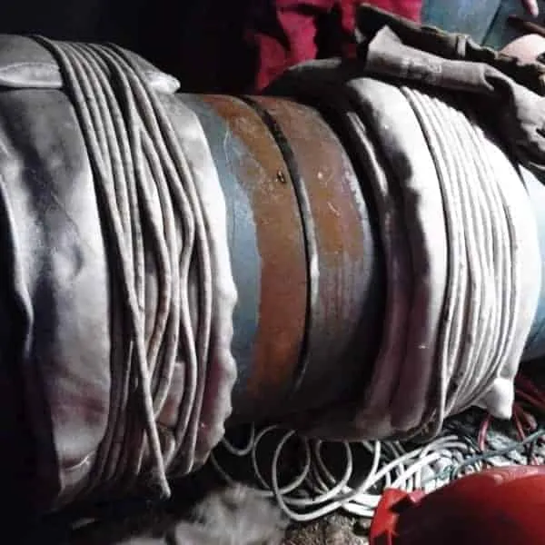
Wrap the steel pipe and thermocouples tightly with suitable thermal insulation blankets.
Cover the specified heating region and avoid unwanted gaps.
Step 5: Secure the Blankets with Non-Metallic Insulating Straps
Use suitable high-temperature, non-metallic insulating straps or cloth to hold the thermal insulation blankets firmly in place.
Do not use unapproved metallic fixing bands or steel wires in the active induction heating region.
Step 6: Wind the Induction Heating Cable
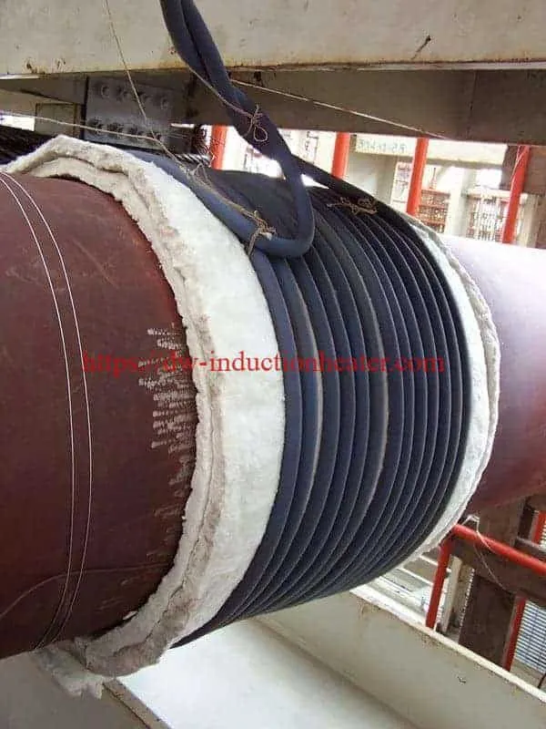
Install the flexible induction heating cable around the outside of the thermal insulation blanket.
Maintain the required coil spacing and arrangement according to the approved equipment configuration.
Step 7: Connect the Heating System
Connect the induction coil and thermocouple cables to the appropriate equipment terminals.
Inspect the electrical supply, grounding, coil connections and cooling arrangements.
Step 8: Set the Heating Parameters
Configure the target temperature and available control functions according to the approved heating procedure.
For formal heat treatment, confirm the required heating rate, soaking time and cooling rate.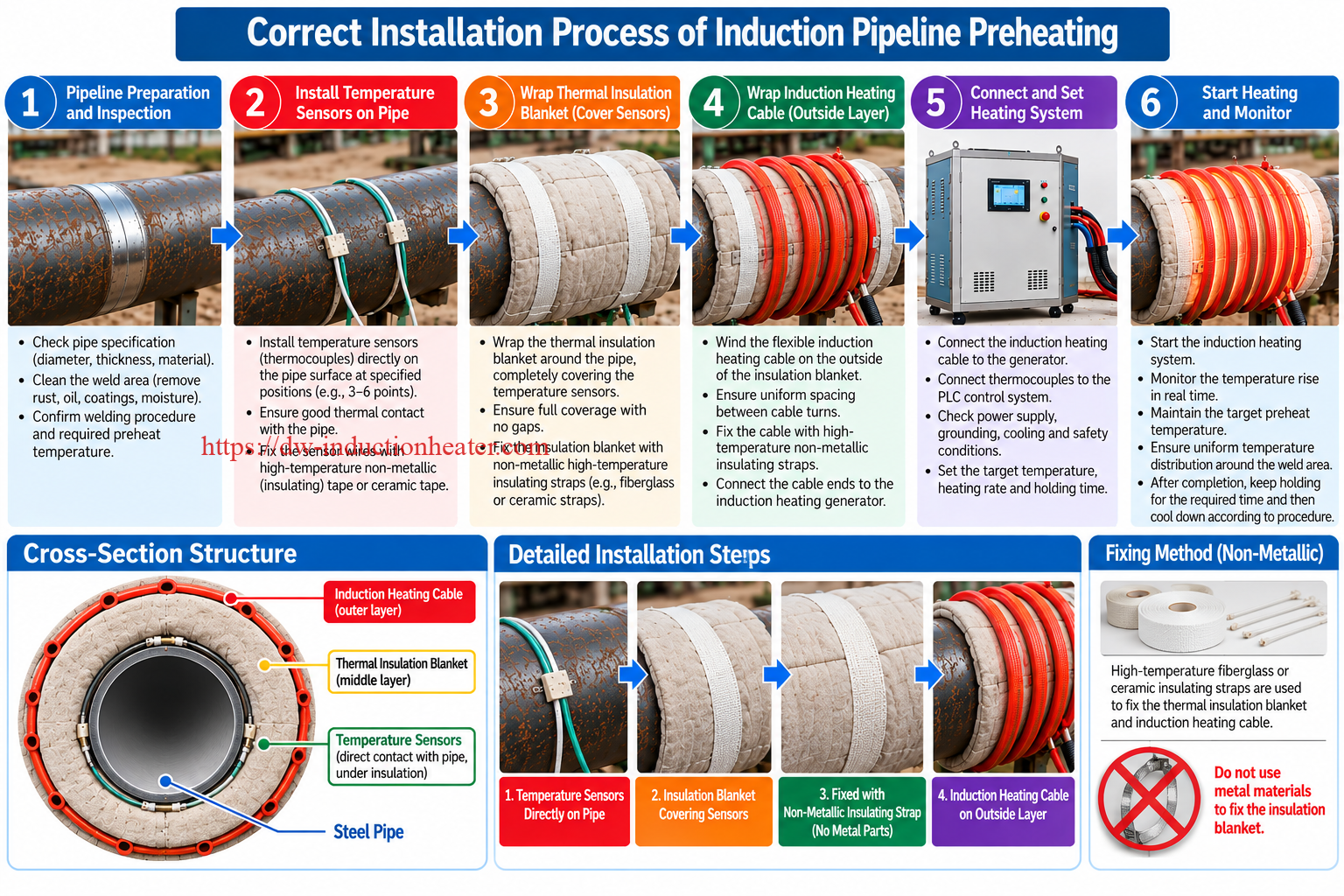
Step 9: Start Heating
Energize the induction heating system and monitor the temperature response of the workpiece.
Verify that the required measurement points reach the specified temperature.
Step 10: Complete the Heating Cycle
Maintain the prescribed temperature for the required duration.
Follow the approved cooling procedure and retain temperature records when required.
Installation Quality Checklist
| Inspection Item | Required Condition |
|---|---|
| Workpiece Surface | Suitable for the specified heating process. |
| Thermocouples | Direct metal contact at approved measurement positions. |
| Thermal Insulation | Covering both pipe and sensors. |
| Insulation Fixing | Non-metallic, high-temperature insulating straps. |
| Induction Heating Cable | Installed outside the insulation blanket. |
| Coil Spacing | Matches the approved heating arrangement. |
| Electrical Connections | Correct and secure. |
| Cooling System | Suitable for the planned operating conditions. |
| Temperature Measurement | Reliable readings before heating begins. |
| Operating Procedure | Approved target temperature and thermal cycle. |
Common Problems and Solutions
The heating performance of an induction preheat welding machine depends on electrical input, generator configuration, workpiece material, coil matching, insulation and operating conditions.
Industrial Troubleshooting Table
| Problem | Possible Cause | Recommended Action |
|---|---|---|
| Slow Heating | Insufficient useful thermal power or high workpiece mass. | Recalculate heating load and verify equipment selection. |
| Uneven Temperature Distribution | Irregular coil spacing or uneven heat losses. | Inspect cable arrangement and insulation coverage. |
| Incorrect Thermocouple Reading | Poor sensor contact with the steel. | Reinstall sensors directly against the metal. |
| Temperature Overshoot | Excessive heating rate or control response delay. | Review approved heating parameters and feedback response. |
| Heating Cable Overheating | Incorrect electrical matching or cable configuration. | Stop operation and inspect the approved heating circuit. |
| Unexpected Heating of Fixing Materials | Conductive metal straps near the induction coil. | Stop operation and remove unapproved metallic materials. |
| Generator Overheating | Insufficient cooling or excessive operating duty. | Check the cooling system and operating limits. |
| Unstable Power Output | Electrical supply or load-matching problems. | Inspect the supply and heating circuit using approved procedures. |
| Insufficient Holding Temperature | Thermal losses exceed useful heating power. | Review insulation, coil configuration and generator capacity. |
| Inconsistent Temperature Records | Sensor installation or recording configuration problems. | Check sensor calibration, channel assignment and recorder settings. |
Preventive Maintenance Checklist
| Component | Inspection Requirement | Purpose |
|---|---|---|
| Induction Cable | Inspect insulation and mechanical condition. | Maintain safe operation. |
| Output Connections | Check according to approved electrical maintenance procedures. | Reduce connection-related faults. |
| Thermocouples | Inspect attachment and calibration. | Maintain reliable temperature measurement. |
| Thermal Insulation | Inspect for tears, moisture and thermal damage. | Maintain heat-loss control. |
| Non-Metallic Straps | Check thermal deterioration and mechanical condition. | Maintain secure installation. |
| Generator Cooling | Inspect applicable fans, ventilation and coolant circuits. | Maintain correct equipment temperature. |
| PLC Controller | Verify control functions and fault indications. | Support reliable operation. |
| Temperature Recorder | Check recording and data retrieval functions. | Maintain process traceability. |
Engineering Selection Guide
Proper generator selection begins with the amount of thermal energy required by the workpiece and the time available for heating.
The nominal output rating of an induction generator does not equal the useful thermal power absorbed by the selected metal region.
1. Calculate the Heated Pipe Mass
For a cylindrical pipe with a selected axial heating band, the heated metal mass can be estimated using:
m = π × (D − t) × t × L × ρ
Where:
- m = selected metal mass, kg.
- D = outside diameter, m.
- t = wall thickness, m.
- L = axial heating-band length, m.
- ρ = material density, kg/m³.
2. Calculate the Required Thermal Energy
The approximate sensible heat required is:
Q = m × Cp × ΔT
Where:
- Q = thermal energy, kJ.
- m = heated metal mass, kg.
- Cp = average specific heat capacity, kJ/(kg·K).
- ΔT = required temperature increase, K.
This formula estimates the energy needed to heat the selected workpiece volume under simplified conditions.
It does not include all thermal losses or heat conducted into adjacent metal during the actual process.
3. Engineering Example: Heating a 323.9 mm Steel Pipe
Consider a hypothetical carbon-steel pipeline welding preheat application.
| Engineering Parameter | Assumed Value |
|---|---|
| Pipe Outside Diameter | 323.9 mm |
| Wall Thickness | 12.7 mm |
| Axial Heating Band | 400 mm |
| Initial Temperature | 25°C |
| Target Temperature | 200°C |
| Temperature Increase | 175 K |
| Assumed Steel Density | 7,850 kg/m³ |
| Assumed Average Specific Heat | 0.50 kJ/(kg·K) |
4. Calculate the Selected Pipe Mass
m = π × (0.3239 − 0.0127) × 0.0127 × 0.400 × 7850
m ≈ 38.99 kg
5. Calculate the Sensible Heat
Q = 38.99 × 0.50 × 175
Q ≈ 3,411 kJ
Converting to kilowatt-hours:
Q = 3411 / 3600
Q ≈ 0.948 kWh
This value is the approximate sensible heat required by the selected pipe-band volume.
It is not the electrical consumption of the generator.
6. Estimate Idealized Heating Time
If the average useful thermal power absorbed by the selected pipe region is known:
Heating Time = Required Thermal Energy / Average Useful Thermal Power
| Assumed Average Useful Thermal Power | Calculated Idealized Heating Time |
|---|---|
| 5 kW | 11.37 minutes |
| 10 kW | 5.69 minutes |
| 15 kW | 3.79 minutes |
| 20 kW | 2.84 minutes |
| 25 kW | 2.27 minutes |
| 30 kW | 1.90 minutes |
Engineering clarification: The useful thermal powers in this table are hypothetical assumptions, not measured performance results for any MYD model.
Actual heating time may be longer because of axial heat conduction, radiation, convection, coil coupling, required temperature uniformity and equipment operating limitations.
7. Why Generator Power Differs from Useful Heating Power
| Power or Energy Term | Definition | Engineering Consideration |
|---|---|---|
| Electrical Input Power | Electrical power drawn from the supply. | Depends on voltage, current and power factor. |
| Generator Output Power | High-frequency electrical output to the induction circuit. | Depends on generator efficiency and load. |
| Useful Thermal Power | Thermal power absorbed by the relevant workpiece region. | Depends on electromagnetic coupling and heat distribution. |
| Thermal Losses | Heat lost to surroundings or adjacent regions. | Depends on insulation and operating conditions. |
8. Important Parameters for Industrial Model Selection
| Parameter | Effect on Equipment Sizing |
|---|---|
| Pipe Diameter | Influences circumference and coil length. |
| Wall Thickness | Influences metal mass and heat distribution. |
| Heating Band Width | Determines selected heated volume. |
| Target Temperature | Determines required sensible heat. |
| Heating Time | Determines average useful power demand. |
| Thermal Insulation | Affects external heat losses. |
| Material Grade | Affects electromagnetic and thermal behavior. |
| Operating Duty | Determines sustained output requirements. |
| Site Electrical Supply | Determines installation feasibility. |
| Temperature Uniformity | May require multiple measurement points and adjusted coil layouts. |
9. Welding Preheating Versus Formal PWHT
| Process | Purpose | Control Requirement |
|---|---|---|
| Preheating | Establish temperature before welding. | Specified minimum preheat temperature. |
| Interpass Temperature Control | Manage temperature between welding passes. | Approved temperature range. |
| Postheating | Maintain temperature after welding when required. | Prescribed holding temperature and time. |
| PWHT | Apply a qualified post-weld thermal treatment. | Heating rate, soaking temperature, holding period, cooling rate and records. |
Industrial pressure equipment and critical welded structures may require compliance with specific design codes and approved thermal procedures.
For related applications, see HLQ induction heating for pressure vessels.
Advantages and Limitations
Main Advantages
1. Industrial Power Range
The published MYD series provides six nominal ratings from 40 kW to 120 kW for industrial induction heating applications.
2. Localized Electromagnetic Heating
Induction heating generates heat within conductive metal materials rather than relying only on external heat transfer.
3. Flexible Coil Arrangements
Compatible flexible induction heating cables can be arranged around suitable cylindrical and other accessible workpiece geometries.
4. PLC Touchscreen Control
The published system includes PLC-based operator control for supported heating functions.
5. Multi-Point Temperature Monitoring
The source page describes multi-point temperature measurement and six-channel capability.
The exact sensor configuration and control performance must be confirmed for the selected equipment.
6. Temperature Recording Options
Temperature recording may support process documentation when the appropriate recorder and software functions are provided.
7. Reduced Dependence on Open Flames
Induction heating does not require a combustion flame as the primary heat source.
Nevertheless, the hot workpiece, electrical power system and surrounding environment still require suitable industrial safety controls.
Important Technical Limitations
| Limitation | Engineering Explanation | Recommended Action |
|---|---|---|
| Electrical Input Rating | Historical input-current values conflict with nominal output ratings. | Verify current factory electrical specifications. |
| Continuous Operating Duty | The source does not fully characterize full-load operating conditions. | Confirm sustained output and cooling requirements. |
| Temperature Precision | The stated ±3°C tolerance lacks test conditions. | Verify measurement and control performance. |
| Energy-Saving Claims | Published savings percentages lack comparative test data. | Use measured application-specific efficiency results. |
| Material Compatibility | Different metals have different electromagnetic properties. | Evaluate the actual material and heating arrangement. |
| Large Workpiece Mass | High thermal loads may require longer heating time. | Calculate required energy and useful power. |
| Coil Installation | Incorrect arrangement may affect heating distribution. | Follow approved coil geometry and fastening procedures. |
| PWHT Compliance | Generator power and PLC control alone do not establish code compliance. | Use a qualified heating procedure and verified recording system. |
Induction Heating Compared with Other Heating Methods
| Comparison | Induction Heating | Flame Heating | Resistance Heating |
|---|---|---|---|
| Heat Generation | Electrical losses inside conductive metal. | External combustion. | Electrical resistance elements. |
| Open Flame | Not required. | Required. | Not required. |
| Heating Distribution | Depends on coil arrangement. | Depends on flame placement. | Depends on heater placement. |
| Temperature Monitoring | Can use direct-contact thermocouples. | Requires suitable measurement equipment. | Can use thermocouples. |
| Primary Limitation | Electromagnetic coupling and electrical matching. | Combustion and heat-transfer control. | Element contact and thermal transfer. |
| Energy Efficiency | Application-dependent. | Application-dependent. | Application-dependent. |
Quantitative energy savings and heating-speed improvements should be established through representative tests on equivalent workpieces under comparable operating conditions.
Why Choose HLQ?
HLQ Induction Equipment Co., Ltd. supplies industrial induction heating equipment for metal processing, welding preparation, localized thermal treatment and related manufacturing applications.
Industrial MYD Power Configurations
The MYD series provides published nominal output ratings from 40 kW to 120 kW, allowing different generator sizes to be evaluated for industrial heating requirements.
Application-Oriented Induction Coil Design
Flexible and application-specific induction coil arrangements can be evaluated for suitable pipes, fittings and fabricated metal components.
PLC-Based Heating Control
The published equipment supports PLC touchscreen operation and temperature-monitoring functions.
Temperature Recording Options
Selected configurations can be equipped with temperature recording functions for monitored thermal processes.
Engineering-Based Equipment Selection
Appropriate equipment selection requires consideration of material grade, dimensions, heated mass, target temperature, heating time, electrical supply and operating duty.
Related Industrial Thermal Applications
HLQ induction heating equipment covers welding preheating, pipe heating, industrial heat treatment and other application-specific metal heating processes.
For broader equipment comparisons, see HLQ air-cooled induction heating systems and welding preheating and stress relieving systems.
10 Core FAQs
1. What is an induction preheat welding machine?
An induction preheat welding machine is an industrial electrical heating system that uses electromagnetic induction to raise the temperature of conductive metal before welding. It is commonly used for suitable steel pipes, welded joints and fabricated components.
2. What power ratings are available in the HLQ MYD series?
The original product page lists six nominal output ratings: 40 kW, 50 kW, 60 kW, 80 kW, 100 kW and 120 kW.
3. What is the output frequency of the MYD induction preheating machine?
The audited product page lists an output frequency range of 2–36 kHz. Actual operating frequency depends on the equipment configuration and connected induction load.
4. Can the MYD machine preheat carbon steel pipelines?
Yes, when the generator and heating coil are suitable for the pipe geometry, material and required heating cycle. Final equipment selection must consider wall thickness, heating-zone width, target temperature and heating time.
5. Where should thermocouples be installed?
Thermocouple junctions should contact the steel pipe directly at the specified measurement locations. The thermal insulation blanket must then cover the sensors and pipe, while the induction heating cable is installed outside the insulation.
6. Can metallic straps be used to secure the insulation blanket?
Unapproved metallic bands and steel wire should not be used in the active induction heating region. Suitable non-metallic, high-temperature insulating straps should be used according to the approved installation procedure.
7. Does the MYD induction heating machine require water cooling?
The original page emphasizes air-cooled construction. However, the exact cooling requirements of the generator, heating coil and accessories must be verified for each model and operating configuration. Air-cooled generator construction does not automatically establish that every system component requires no water cooling.
8. Is the published ±3°C temperature tolerance guaranteed?
The original page claims ±3°C temperature tolerance but does not define the measurement location, test conditions or calibration requirements. Actual performance must be confirmed against current factory specifications and relevant process requirements.
9. Can the MYD machine perform post-weld heat treatment?
The equipment may be evaluated for selected post-weld thermal treatment applications. Formal PWHT requires a qualified thermal cycle, suitable heating power, temperature monitoring, control functions and process records. Nominal generator power alone does not establish compliance with a particular heat-treatment standard.
10. How do I select the correct induction preheat welding machine?
Identify the material grade, pipe diameter, wall thickness, heating band width, initial temperature, target temperature, required heating time, holding requirements and available electrical supply. Calculate the approximate thermal energy requirement and verify the selected generator’s useful heating performance, cooling requirements and continuous operating duty.