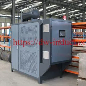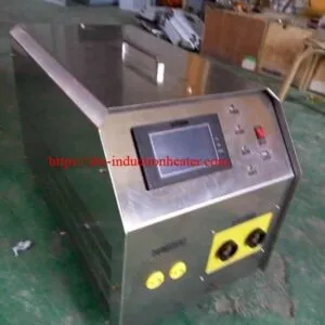


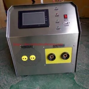

Portable Induction Preheat Welding System
Portable Induction Preheat Welding System for Steel Pipes and Weld Joints
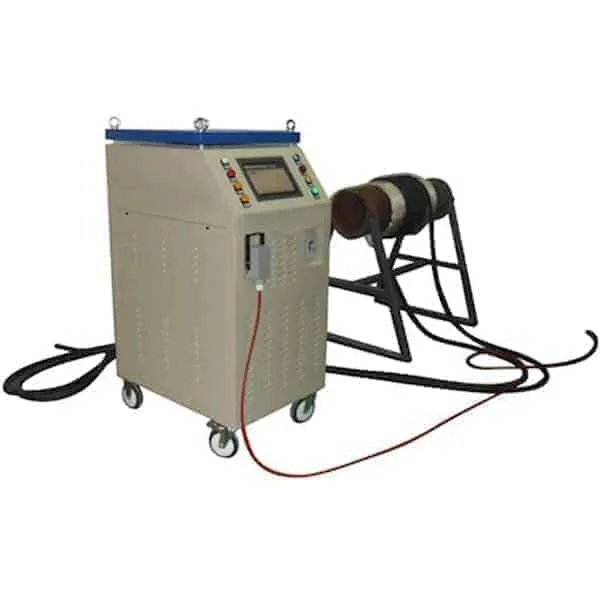
The HLQ Portable Induction Preheat Welding System is a compact, air-cooled induction heating solution developed for localized steel pipe heating, weld joint preheating, metal fabrication and selected industrial maintenance applications.
Available in MYD-10KW and MYD-20KW configurations, the portable system offers published output power ranges of 1–10 kW and 1–20 kW, respectively. Both models operate within a published induction output frequency range of 5–30 kHz.
By generating heat directly inside electrically conductive materials, induction heating provides an alternative to conventional flame-based heating for suitable welding applications.
The system combines a portable induction power supply, flexible induction heating cable, temperature monitoring and application-specific thermal insulation.
Actual heating performance depends on the workpiece material, wall thickness, coil configuration, target temperature, heating-zone width and available useful thermal power.

Quick Answer
What is a portable induction preheat welding system?
A portable induction preheat welding system is an electrically powered machine that uses a high-frequency magnetic field to generate heat inside conductive metal before welding.
The HLQ MYD-10KW and MYD-20KW models are designed for suitable localized heating tasks involving steel pipes, welded joints and fabricated metal components.
Both models use a published three-phase 380 V, 50/60 Hz input supply and operate within a listed induction frequency range of 5–30 kHz.
| Quick Technical Answer | MYD-10KW | MYD-20KW |
|---|---|---|
| Nominal Maximum Output | 10 kW | 20 kW |
| Output Frequency | 5–30 kHz | 5–30 kHz |
| Input Voltage | Three-phase 380 V | Three-phase 380 V |
| Machine Weight | 26 kg | 32 kg |
| Temperature Sensor | K-type thermocouple | K-type thermocouple |
| Primary Application | Localized weld preheating | Higher-load localized preheating |
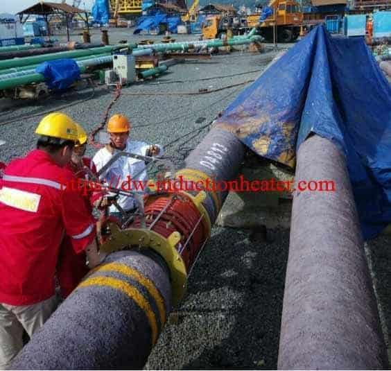
Correct installation: Attach the thermocouples directly to the steel surface. Cover the pipe and sensors with thermal insulation blankets, secure the blankets using suitable non-metallic insulating straps, and then wind the induction heating cable around the outside of the insulation.
Selection note: A 10 kW or 20 kW nameplate does not guarantee a particular pipe heating time. Thermal load calculations and verified operating ratings are required before final equipment selection.
Table of Contents
- What Is a Portable Induction Preheat Welding System?
- Key Applications
- Suitable Materials
- Working Principle
- Technical Specifications
- Recommended Model Selection
- Process Workflow
- Common Problems and Solutions
- Engineering Selection Guide
- Advantages and Limitations
- Why Choose HLQ?
- 10 Core FAQs
What Is a Portable Induction Preheat Welding System?
A portable induction preheat welding system is an industrial heating machine that uses electromagnetic induction to raise the temperature of a selected metal region before welding begins.
Welding preheating is often required when the welding procedure specifies a minimum base-metal temperature. Depending on the steel grade, welding process and joint geometry, preheating may reduce weld cooling rates and help control conditions associated with hydrogen-assisted cracking.
Unlike conventional flame heating, induction heating does not rely on combustion at the workpiece surface. Instead, high-frequency current flowing through an induction coil produces an alternating magnetic field that induces electrical currents in the metal.
The induced currents generate resistive heating within the conductive material.
Main Components
| System Component | Primary Function | Selection Requirement |
|---|---|---|
| Portable Induction Generator | Produces high-frequency electrical power. | Output rating, frequency and duty. |
| Power Control Panel | Controls available heating functions. | Model-specific control capability. |
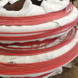
| Flexible Induction Heating Cable | Creates an alternating magnetic field around the workpiece. | Cable dimensions and load matching. |
| K-Type Thermocouple | Measures metal temperature. | Direct metal contact and calibration. |
| Thermal Insulation Blanket | Reduces heat loss from the treatment area. | Appropriate temperature rating. |
| Non-Metallic Insulating Straps | Secure insulation and heating cables. | High-temperature resistance and mechanical strength. |
| Electrical Connections | Connect generator, coil and sensors. | Electrical compatibility and secure installation. |
| Cooling System | Removes heat from designated generator components. | Ventilation and operating-duty limits. |
Portable Design for Industrial Workplaces
The MYD-10KW has published dimensions of 650 × 310 × 410 mm and weighs approximately 26 kg.
The MYD-20KW measures approximately 700 × 330 × 410 mm and weighs 32 kg.
These compact dimensions make the portable MYD series more manageable for relocation between suitable workshop stations and approved field applications.
However, portable equipment still requires appropriate electrical protection, proper cable handling, ventilation and a safe working environment.

Key Applications
1. Carbon Steel Welding Preheating
Carbon steel weldments may require preheating according to their chemical composition, thickness, restraint level and welding procedure.
Induction heating can provide a controlled source of heat for the specified preheat zone when the heating cable is correctly installed and the equipment is appropriately sized.
The target preheat temperature must be established by the approved welding procedure specification (WPS).
2. Steel Pipe Joint Preheating
Pipe welds frequently require heat around the joint circumference before welding.
A flexible induction cable can be arranged around a suitably insulated steel pipe, allowing electromagnetic heating of the underlying metal.
Pipe diameter, wall thickness and heating band width determine the approximate metal mass requiring heat.
3. On-Site Welding Maintenance
Portable induction preheaters may be used in approved field maintenance operations where a compact power generator and flexible cable arrangement are beneficial.
Typical considerations include available three-phase power, ambient temperature, cable routing, operator safety and access to the heating zone.
Additional examples are available in the HLQ portable welding preheating machine application overview.
4. Steel Plate and Fabrication Heating
Localized preheating may be required when welding thick plates, steel fittings, reinforcement components and other fabricated structures.
Suitable induction coil designs can be evaluated for these applications, although the magnetic coupling and thermal response may differ from those of cylindrical pipes.
5. Weld Repair Preparation
Some qualified weld repair procedures require controlled preheating before welding begins.
Portable induction equipment may assist when the required temperature, workpiece geometry and heating time are within the verified equipment capability.
6. Selected Postheating Operations
Certain welding procedures specify controlled heating or temperature holding after welding.
Such operations should be distinguished from formal post-weld heat treatment (PWHT), which may require a complete recorded thermal cycle, multiple temperature measurement points and a prescribed cooling rate.
Application Comparison
| Application | Heating Objective | Critical Requirement |
|---|---|---|
| Pipe Weld Preheating | Reach the specified base-metal temperature. | Pipe geometry and approved WPS. |
| Structural Steel Preheating | Condition the weld area before joining. | Material grade, restraint and joint thickness. |
| Workshop Fabrication | Heat a selected component region. | Coil geometry and metal mass. |
| On-Site Weld Repair | Provide localized heating for an approved repair. | Power availability and worksite safety. |
| Interpass Temperature Management | Maintain temperatures within the qualified range. | Temperature monitoring and welding procedure. |
| Localized Postheating | Hold a specified post-weld temperature. | Approved holding time and temperature. |
Suitable Materials
Induction heating works with electrically conductive materials. Its effectiveness depends on the workpiece’s electromagnetic and thermal properties.
Ferromagnetic carbon steels often exhibit favorable magnetic coupling at suitable temperatures, while non-magnetic stainless steels and highly conductive nonferrous metals can require different coil and power arrangements.
Material Suitability Matrix
| Workpiece Material | General Suitability | Engineering Consideration |
|---|---|---|
| Low-Carbon Steel | Generally Suitable | Common weld preheating material. |
| Structural Carbon Steel | Generally Suitable | Follow applicable welding specifications. |
| Carbon Steel Pipe | Generally Suitable | Heating band and wall thickness determine load. |
| Low-Alloy Steel | Application-Dependent | Requires grade-specific preheat control. |
| Cr-Mo Alloy Steel | Conditional | May require defined preheat and PWHT cycles. |
| Quenched and Tempered Steel | Conditional | Excessive heating may affect mechanical properties. |
| Ferritic Stainless Steel | Application-Dependent | Magnetic characteristics vary with grade and temperature. |
| Austenitic Stainless Steel | Requires Engineering Evaluation | Different coupling characteristics from carbon steel. |
| Cast Iron | Conditional | Thermal stress and crack sensitivity require attention. |
| Aluminum and Copper | Specialized Applications | Coil design and generator matching must be verified. |
Material Properties Affecting Heating Performance
| Property | Effect on Induction Preheating |
|---|---|
| Electrical Resistivity | Influences electrical losses inside the metal. |
| Magnetic Permeability | Affects magnetic coupling and current penetration. |
| Thermal Conductivity | Controls the transfer of heat to adjacent regions. |
| Specific Heat Capacity | Determines the energy required for a temperature rise. |
| Wall Thickness | Affects heated mass and through-wall temperature distribution. |
| Initial Temperature | Determines the required temperature increase. |
| Heat Treatment Condition | May restrict permissible heating temperature. |
Working Principle
How Does an Induction Welding Preheater Work?
The portable induction generator converts three-phase AC input power into high-frequency electrical power.
The generator supplies alternating current to the induction heating cable, which produces an alternating magnetic field around the metal workpiece.
The magnetic field induces electrical currents within the conductive steel. Resistive electrical losses then convert energy into heat.
Heat spreads through the pipe wall and along the workpiece by thermal conduction.
Thermocouples installed directly on the metal surface provide workpiece temperature readings for monitoring and available control functions.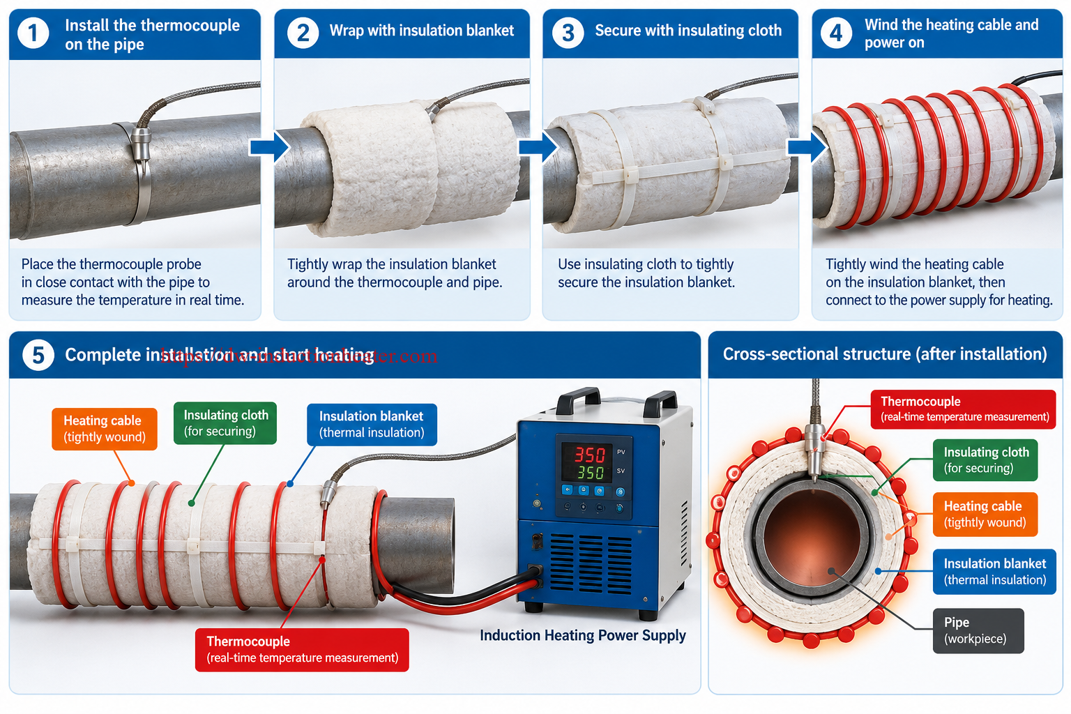
Electromagnetic Heating Stages
| Stage | Process | Technical Result |
|---|---|---|
| 1 | Three-phase input power | Electrical energy enters the generator. |
| 2 | High-frequency conversion | The induction power supply produces high-frequency output. |
| 3 | Induction cable energization | An alternating magnetic field develops. |
| 4 | Eddy current generation | Current is induced in the conductive workpiece. |
| 5 | Resistive heating | Electrical energy is converted into heat within the metal. |
| 6 | Thermal conduction | Heat spreads through the workpiece. |
| 7 | Temperature measurement | Thermocouples measure selected surface temperatures. |
| 8 | Heating control | Available controls adjust the thermal process. |
Correct Layer Arrangement for Pipe Heating
The temperature sensors, thermal insulation and induction cable must be installed in the correct order.
Correct installation sequence:
- Prepare the steel pipe surface.
- Install K-type thermocouples directly against the steel pipe.
- Wrap the thermocouples and pipe tightly with thermal insulation blankets.
- Secure the blankets with suitable non-metallic, high-temperature insulating straps.
- Wind the flexible induction heating cable around the outside of the thermal insulation blankets.
- Secure the cable using approved electrically insulating fixing materials.
- Connect the heating cable and thermocouples to the appropriate equipment terminals.
- Verify the installation before energizing the heating system.
Cross-Section Arrangement
| Position | Component | Purpose |
|---|---|---|
| Inner Workpiece | Steel Pipe | Metal heated by induction. |
| Direct Metal Contact | Temperature Sensor | Measures actual pipe surface temperature. |
| Middle Layer | Thermal Insulation Blanket | Covers pipe and sensors; reduces heat loss. |
| Outer Layer | Induction Heating Cable | Generates the alternating magnetic field. |
| Fixing Method | Non-Metallic Insulating Straps | Secure the insulation and cable as specified. |
Important: Do not use unapproved metallic bands, steel wire or conductive straps around the thermal insulation blanket in the active induction-heating zone. Such materials may experience unwanted induction heating or create other installation hazards.
Suitable non-metallic fixing materials may include properly rated fiberglass or ceramic insulating straps, depending on the operating temperature and equipment instructions.
For specialized coil arrangements, review HLQ flexible induction heating cables and related induction coil configurations.
Why Thermal Insulation Matters
Although heat is generated inside the workpiece, thermal energy can still be lost through convection, radiation and conduction into nearby metal.
Properly installed thermal insulation reduces external heat loss and may help improve heating effectiveness.
However, insulation thickness also changes the distance between the induction cable and the metal, which can influence electromagnetic coupling.
Consequently, insulation thickness and cable arrangement must be considered together during system design.

Technical Specifications
The following specifications reproduce the key technical information published for the MYD-10KW and MYD-20KW portable induction heating systems.
Several historical figures require confirmation because the source does not state complete test conditions or continuous operating limits.
MYD-10KW and MYD-20KW Technical Data
| Parameter | MYD-10KW | MYD-20KW |
|---|---|---|
| Nominal Output Power Range | 1–10 kW | 1–20 kW |
| Input Voltage | 3 × 380 V | 3 × 380 V |
| Input Frequency | 50/60 Hz | 50/60 Hz |
| Published Input Connection | 4 Wires | 4 Wires |
| Published Input Current | 1–15 A | 1–30 A |
| Published Output Current | 0–200 A | 0–300 A |
| Output Frequency | 5–30 kHz | 5–30 kHz |
| Thermocouple Type | K-Type | K-Type |
| Temperature System | Built-In | Built-In |
| Published Maximum Heating Temperature | 500°C | 800°C |
| Machine Dimensions | 650 × 310 × 410 mm | 700 × 330 × 410 mm |
| Machine Weight | 26 kg | 32 kg |
| Published Heating Cable Length | 10–20 m | 10–20 m |
| Published Heating Cable Diameter | 15 mm | 15 mm |
| Published Ambient Temperature | -30°C to +45°C | -30°C to +45°C |
| Published Pipe Outside Diameter | 50–500 mm | 50–500 mm |
Electrical Input Verification
For a balanced three-phase electrical system, apparent input power can be calculated as:
S = √3 × V × I / 1000
Where S is apparent power in kVA, V is line-to-line voltage and I is line current.
| Model | Published Maximum Input Current | Calculated Apparent Input Power | Published Maximum Output |
|---|---|---|---|
| MYD-10KW | 15 A | 9.87 kVA | 10 kW |
| MYD-20KW | 30 A | 19.75 kVA | 20 kW |
Because real electrical conversion systems have losses and do not operate above a power factor of 1, the published input-current and output-power figures are not fully consistent as simultaneous continuous ratings.
The rated input current, power factor, conversion efficiency and permissible continuous operating duty should be verified against current factory test data.
The historical MYD-10KW specification also mentions a maximum 15 kW output at a 150% duty condition, but does not define the allowed operating duration. This figure should not be interpreted as a guaranteed continuous output rating.
Operating Environment and Accessories
| Item | Published Information | Verification Requirement |
|---|---|---|
| Cooling Arrangement | Air-cooled equipment category | Confirm ventilation and operating-duty limits. |
| Ambient Range | -30°C to +45°C | Confirm latest tested operating conditions. |
| Heating Cable | 10–20 m; 15 mm diameter | Confirm supplied length and electrical matching. |
| Temperature Measurement | K-type thermocouple | Confirm channel count and measurement accuracy. |
| Temperature Recording | Not fully defined on source page | Verify whether records can be stored or exported. |
| Thermal Insulation | Used for suitable pipe heating arrangements | Confirm material, rating and scope of supply. |
| Insulating Fixing Straps | Application-specific accessories | Confirm material and thermal rating. |
For an overview of related power-supply configurations, see HLQ air-cooled induction heating system equipment.
Recommended Model Selection
Choosing the correct portable induction heater requires more than comparing nominal output power.
The workpiece material, dimensions, desired temperature rise, heating time and available useful thermal power must all be considered.
MYD-10KW vs. MYD-20KW
| Selection Parameter | MYD-10KW | MYD-20KW |
|---|---|---|
| Nominal Maximum Output | 10 kW | 20 kW |
| Weight | 26 kg | 32 kg |
| Cabinet Size | Smaller | Larger |
| Published Temperature Ceiling | 500°C | 800°C |
| Preliminary Application | Lower thermal loads and localized heating | More demanding localized heating applications |
| Actual Heating Time | Application-dependent | Application-dependent |
| Continuous-Duty Performance | Requires verification | Requires verification |
Preliminary Application-Based Recommendations
| Heating Application | Preliminary Model Consideration | Required Verification |
|---|---|---|
| Small Steel Pipe Weld Preheating | MYD-10KW | Wall thickness, heated length and target time. |
| Localized Steel Fitting Heating | MYD-10KW / MYD-20KW | Material mass and coil coupling. |
| Moderate Pipe Joint Heating | MYD-20KW | Pipe dimensions and average useful power. |
| Industrial Field Welding | Application-Dependent | Electrical input, worksite conditions and WPS. |
| Localized Postheating | Application-Dependent | Holding temperature, time and duty cycle. |
| Large-Diameter, Thick-Wall Piping | Evaluate a Higher-Power System | Full thermal calculation and heating uniformity. |
| Code-Controlled PWHT | Specialized System Assessment | Approved thermal cycle, records and validated control. |
For larger workpieces or higher heating loads, compare a dedicated induction pipeline preheating machine.
Information Required for Equipment Sizing
| Input Data | Reason |
|---|---|
| Material Grade | Determines thermal and electromagnetic characteristics. |
| Pipe Outside Diameter | Influences cable length and coil arrangement. |
| Wall Thickness | Determines approximate heated metal mass. |
| Heating Band Width | Determines the selected heating region. |
| Initial Temperature | Establishes the required temperature increase. |
| Target Temperature | Determines sensible heat requirements. |
| Required Heating Time | Influences average useful power requirements. |
| Continuous Operating Duration | Determines power-system duty requirements. |
| Electrical Supply | Determines installation compatibility. |
| Thermal Procedure | Defines permissible heating and cooling conditions. |
Process Workflow
The following workflow describes a typical steel-pipe induction preheating arrangement. Installation details must always follow the actual equipment instructions and applicable welding procedure.
Step 1: Inspect the Pipe and Welding Procedure
Confirm the steel grade, pipe outside diameter, wall thickness, weld location and specified minimum preheat temperature.
Inspect the heating area for coatings, contamination and environmental hazards.
Step 2: Install Temperature Sensors on the Steel Surface
Attach K-type thermocouples directly to the steel at the specified measurement locations.
Use an approved method to maintain reliable thermal contact.
The thermocouple junctions must measure the workpiece temperature, not the surface temperature of the insulation blanket.
Step 3: Wrap the Pipe and Sensors with Thermal Insulation
Install thermal insulation blankets over both the steel pipe and the temperature sensors.
Cover the required heating zone and avoid unnecessary gaps.
Step 4: Secure Insulation with Non-Metallic Straps
Use suitable high-temperature insulating straps to hold the thermal insulation blankets firmly in position.
Do not use unapproved metal fixing bands or steel wire around the active induction heating area.
Step 5: Wind the Induction Heating Cable
Install the flexible induction heating cable around the outside of the thermal insulation blankets.
Maintain the correct number of turns and coil spacing according to the approved configuration.
Use appropriate non-metallic fixing materials or approved cable supports.
Step 6: Connect the Generator and Temperature Sensors
Connect the induction heating cable and thermocouple leads to the designated equipment terminals.
Verify all connections before energizing the system.
Step 7: Check Operating Conditions
Confirm electrical supply compatibility, ventilation, cable insulation, temperature sensor readings and applicable safety arrangements.
Step 8: Set the Heating Parameters
Set the required heating temperature and any available control parameters in accordance with the approved welding or heating procedure.
Step 9: Perform Controlled Preheating
Start the heating process and monitor the workpiece temperature.
Confirm that the required preheat temperature has been achieved at the specified measurement locations before welding begins.
Step 10: Monitor Welding and Complete the Procedure
Maintain the required preheat or interpass temperatures as specified.
After welding, apply any specified postheating or cooling requirements.
Process Inspection Checklist
| Inspection Item | Acceptance Consideration |
|---|---|
| Pipe Surface | Suitable for temperature measurement and approved heating. |
| Thermocouples | Direct metal contact and correct positions. |
| Insulation Coverage | Specified heating zone covered. |
| Fixing Straps | Approved non-metallic insulating material. |
| Induction Cable | Outside the insulation with correct arrangement. |
| Electrical Connections | Secure and compatible with the equipment. |
| Temperature Control | Suitable for the prescribed process. |
| Operator Safety | Work area and equipment checks completed. |

Common Problems and Solutions
Portable induction preheating performance can be affected by the heating cable, sensor position, generator matching, workpiece geometry and surrounding thermal conditions.
Industrial Troubleshooting Table
| Problem | Possible Cause | Recommended Action |
|---|---|---|
| Heating Is Too Slow | Large thermal load or insufficient useful heating power. | Recalculate metal mass and verify equipment capability. |
| Pipe Temperature Is Uneven | Irregular cable spacing or excessive heat loss. | Inspect cable arrangement and insulation coverage. |
| Temperature Display Is Incorrect | Thermocouple not contacting metal correctly. | Check direct contact and sensor installation. |
| Temperature Overshoot | Heating rate too high or control response delayed. | Review control settings and sensor response. |
| Induction Cable Overheats | Incorrect installation, load matching or operating duty. | Stop operation and inspect the heating circuit. |
| Fixing Material Becomes Hot | Unapproved metallic fastening material. | Stop operation and replace it with approved insulating fixtures. |
| Generator Temperature Rises | Insufficient airflow or excessive equipment load. | Inspect ventilation and continuous-duty limits. |
| Insufficient Heat Penetration | Wall thickness and thermal conduction effects. | Evaluate through-wall temperature and heating time. |
| Unstable Power Output | Load matching, cable or connection problems. | Inspect the system using approved service procedures. |
| Holding Temperature Cannot Be Maintained | Thermal losses exceed available useful heating power. | Review insulation, generator capacity and operating conditions. |
Preventive Maintenance
| Component | Recommended Inspection |
|---|---|
| Induction Cable | Inspect insulation, mechanical wear and termination condition. |
| Temperature Sensors | Check contact, damage and calibration. |
| Thermal Insulation | Inspect for moisture, tears and thermal deterioration. |
| Non-Metallic Straps | Inspect strength and temperature suitability. |
| Generator Cooling | Confirm suitable airflow and clear ventilation paths. |
| Electrical Connections | Check using approved de-energized inspection procedures. |
| Control Functions | Verify measurements and operating indications. |
Preheating and Postheating Are Different Processes
Preheating prepares the metal before welding. Postheating applies heat after welding when a procedure requires it.
For applications focused on the latter process, see portable induction postheating equipment and its application requirements.
Engineering Selection Guide
1. Determine the Required Heated Metal Mass
For a steel pipe, the approximate mass of a selected axial heating band can be calculated using:
m = π × (D − t) × t × L × ρ
Where:
- m = heated steel mass, kg.
- D = pipe outside diameter, m.
- t = pipe wall thickness, m.
- L = selected axial heating length, m.
- ρ = steel density, kg/m³.
2. Calculate the Sensible Heat Requirement
Q = m × Cp × ΔT
Where:
- Q = thermal energy, kJ.
- m = heated mass, kg.
- Cp = average specific heat capacity, kJ/(kg·K).
- ΔT = temperature increase, K.
The equation estimates the energy needed to increase the temperature of the selected metal mass. It does not account for all real operating losses.
3. Engineering Example: Preheating a 168.3 mm Steel Pipe
Consider a hypothetical carbon steel pipe preheating application.
| Engineering Input | Value |
|---|---|
| Pipe Outside Diameter | 168.3 mm |
| Pipe Wall Thickness | 7.11 mm |
| Heating Band Length | 250 mm |
| Initial Temperature | 25°C |
| Target Temperature | 150°C |
| Temperature Increase | 125 K |
| Assumed Steel Density | 7,850 kg/m³ |
| Assumed Average Specific Heat | 0.49 kJ/(kg·K) |
Step A: Calculate the Pipe Heating Band Mass
m = π × (0.1683 − 0.00711) × 0.00711 × 0.250 × 7850
m ≈ 7.07 kg
Step B: Calculate the Sensible Heat
Q = 7.07 × 0.49 × 125
Q ≈ 433 kJ
Q ≈ 0.120 kWh
This is the estimated sensible heat for the selected pipe band, not the actual electrical energy consumed by the generator.
4. Estimate Heating Time
For an assumed average useful thermal power delivered to the selected workpiece region:
Heating Time (seconds) = Q (kJ) / Useful Thermal Power (kW)
| Assumed Useful Thermal Power | Idealized Heating Time | Engineering Interpretation |
|---|---|---|
| 1.5 kW | 289 seconds | Lower useful heat delivery. |
| 3.0 kW | 144 seconds | Moderate useful heat delivery. |
| 5.0 kW | 87 seconds | Higher useful heat delivery. |
| 6.0 kW | 72 seconds | Higher useful heat delivery. |
Important engineering note: The assumed useful power values in this table are hypothetical. They are not measured MYD-10KW or MYD-20KW performance results.
Actual heating time will usually differ because of heat conduction into adjacent pipe sections, thermal radiation, convection, insulation performance, coil coupling and operating limitations.
5. Heating Load Sensitivity
| Changed Parameter | General Effect on Required Energy |
|---|---|
| Greater Pipe Wall Thickness | Increases heated metal mass. |
| Larger Outside Diameter | Increases heated circumference for a given band width. |
| Wider Heating Band | Increases the selected heated volume. |
| Higher Target Temperature | Increases required sensible heat. |
| Lower Initial Temperature | Increases required temperature rise. |
| Poorer Thermal Insulation | Can increase heat losses. |
| Shorter Required Heating Time | Increases average useful power demand. |
6. Engineering Model Selection Procedure
- Identify the workpiece material and applicable welding requirements.
- Determine the outside diameter, thickness and heating band width.
- Calculate the selected heated metal mass.
- Calculate the approximate sensible heat requirement.
- Estimate additional thermal losses and adjacent heated mass.
- Determine the required useful thermal power from the allowable heating time.
- Compare the required thermal load with verified generator and coil performance.
- Confirm electrical input, operating duty and temperature control capability.
- Validate the final heating configuration through a representative trial.
7. Welding Preheating Versus Formal PWHT
| Process | Main Objective | Typical Control Requirement |
|---|---|---|
| Weld Preheating | Prepare the metal before welding. | Specified minimum preheat temperature. |
| Interpass Temperature Control | Manage weld area temperature between passes. | Qualified minimum and maximum limits. |
| Localized Postheating | Maintain a specified temperature after welding. | Holding temperature and time. |
| Formal PWHT | Apply a qualified thermal treatment after welding. | Heating rate, soaking temperature, holding time, cooling rate and records. |
Formal PWHT requires compliance with the applicable procedure and standards. A portable induction heater alone does not guarantee a qualified PWHT cycle.
For applications requiring comprehensive heating-cycle control and documentation, compare dedicated induction PWHT equipment.
Advantages and Limitations
Main Advantages
1. Compact and Portable
The MYD-10KW and MYD-20KW have published machine weights of 26 kg and 32 kg, respectively.
The compact design can be advantageous for suitable welding workstations and selected maintenance locations.
2. Localized Heating
Induction cables allow the magnetic field to be arranged around selected conductive metal components.
3. No Combustion Flame at the Workpiece
The heating process does not require an open gas flame as its primary heat source.
However, hot metal, electrical energy and surrounding flammable materials still require appropriate safety controls.
4. Flexible Cable Installation
Suitable flexible induction cables can be configured around cylindrical steel pipes and selected other component shapes.
5. Temperature Monitoring
The published MYD portable equipment includes K-type thermocouple temperature-monitoring capability.
6. Reduced External Heat Loss with Insulation
Proper insulation can help reduce heat loss from the selected workpiece area.
The actual improvement depends on the thermal conditions and installation configuration.
Technical Limitations
| Limitation | Engineering Consideration |
|---|---|
| Limited Nominal Generator Power | Large pipe sections may need higher-power equipment. |
| Workpiece Dependency | Material and geometry influence coupling and heat transfer. |
| Continuous-Duty Limits | Historical full-load operating limits require verification. |
| Temperature Restrictions | Material limits may be below the published machine temperature ceiling. |
| Electrical Input Requirements | Published input-current figures require clarification. |
| Sensor Placement | Incorrect installation can produce misleading temperature readings. |
| Metal Fixing Materials | Unapproved conductive hardware may experience unwanted heating. |
| Formal PWHT Compliance | Requires validated thermal control, recording and procedure compliance. |
Induction Heating vs. Flame Heating vs. Resistance Heating
| Comparison | Induction Heating | Flame Heating | Resistance Heating |
|---|---|---|---|
| Heat Generation | Within conductive metal | Combustion outside workpiece | Resistive elements |
| Open Flame | No | Yes | No |
| Heating Distribution | Depends on coil arrangement | Depends on flame placement | Depends on element placement |
| Temperature Monitoring | Can use thermocouples | Requires suitable measurement | Can use thermocouples |
| Main Limitation | Electromagnetic coupling and generator matching | Combustion and heat-transfer control | Heating element placement and thermal transfer |
| Energy Efficiency | Application-dependent | Application-dependent | Application-dependent |
Claims regarding energy savings, heating speed and thermal uniformity should be supported by comparable tests on identical workpieces under equivalent operating conditions.
Why Choose HLQ?
HLQ Induction Equipment Co., Ltd. supplies induction heating equipment for industrial metal processing, welding preparation, localized heat treatment and related manufacturing operations.
Portable MYD Product Options
The MYD-10KW and MYD-20KW provide compact nominal 10 kW and 20 kW configurations for suitable localized heating applications.
Application-Oriented Heating Solutions
Portable induction systems can be evaluated for different pipe diameters, wall thicknesses, steel grades and required heating temperatures.
Flexible Heating Cable Arrangements
Flexible cable configurations allow induction heating to be adapted to selected metal workpiece shapes, subject to electrical matching and safe installation requirements.
Temperature Monitoring
K-type thermocouple monitoring allows the heating process to be evaluated against specified workpiece temperatures.
Engineering-Based Equipment Selection
Equipment selection should use verified electrical ratings and calculations based on material mass, target temperature, heating time and heat losses.
Where performance or duty-cycle data are incomplete, representative testing is important before industrial implementation.
10 Core FAQs
1. What is a portable induction preheat welding system?
It is a compact electrical heating machine that uses electromagnetic induction to raise the temperature of conductive metal before welding. It can be used for suitable steel pipe joints, fabricated components and industrial weld preheating applications.
2. What models are available in the HLQ portable MYD series?
The original product page lists MYD-10KW and MYD-20KW, with published nominal maximum outputs of 10 kW and 20 kW.
3. What output frequency does the MYD portable system use?
The published output frequency range is 5–30 kHz. Actual operation depends on the generator, heating cable and connected workpiece load.
4. Can a portable induction heater preheat carbon steel pipes?
Yes, when the induction cable, generator and heating arrangement are suitable for the pipe geometry and required welding procedure. The target temperature must follow the applicable WPS.
5. What pipe diameters are suitable?
The source page publishes an outside-diameter range of 50–500 mm. This does not guarantee a specified heating time for every pipe in that range. Wall thickness and heating band width are also important.
6. Where should temperature sensors be installed?
Temperature sensors must contact the steel pipe directly at the specified measurement points. The thermal insulation blanket then covers the pipe and sensors, while the induction heating cable is installed outside the insulation.
7. Can metal straps secure the insulation blanket?
Unapproved metal straps or steel wire should not be used in the active induction heating zone. Suitable non-metallic, high-temperature insulating straps should be selected in accordance with the equipment installation procedure.
8. Can MYD-10KW continuously deliver 15 kW?
The original specification mentions 15 kW at a 150% duty condition but does not provide an overload duration or operating limits. Therefore, continuous 15 kW output cannot be assumed.
9. Can MYD-20KW be used for post-weld heat treatment?
It may be evaluated for selected thermal treatment applications, but formal PWHT requires an appropriate qualified process, adequate heating power, temperature control, required measurements and records. Nominal power alone does not establish compliance.
10. How do I select the correct induction welding preheater?
Identify the workpiece material, outside diameter, wall thickness, heating band width, initial temperature, target temperature, required heating time, electrical supply and operating duty. Calculate the thermal load and verify the selected generator and cable performance before use.
HLQ-Portable-Induction-Preheat-Welding-System-Brochure
Related products
-

Air Cooling Induction Heating System
-
Electromagnetic Induction Heater 15KW Magnetic Heater
-
Electromagnetic Induction Heater 10KW for heating plastic injection molding machine
-
Induction Heating for Disassembly and Assembly large bearings, shaft couplings, propeller hubs and Turbine Bearings in Shipbuilding Industry and Heavy Machinery Maintenance
-
Induction thermal oil boiler with electromagnetic induction heating system