
Induction Heating for Billet Forging: Engineering Design and Equipment Selection
Quick Answer
Induction heating for billet forging uses an alternating magnetic field to heat conductive metal stock before deformation in a press or hammer. A suitable system must deliver the required temperature distribution throughout the forging zone at the production line’s required cadence.
Equipment selection starts with material grade, billet geometry, starting temperature, forging temperature window and production demand. These inputs determine the useful heating duty, frequency assessment, coil arrangement, residence time, feeding system, cooling requirements and acceptance tests.
The central engineering rule: select the power supply, coil, handling system and temperature-control strategy as one process. A model name, nominal power value or exit surface temperature alone cannot establish successful through-heating.

Table of Contents
- Quick Answer
- What is Induction Heating for Billet Forging?
- Working Principle
- Key Applications
- Suitable Materials and Industries
- Technical Specifications
- Recommended Model Selection
- Process Workflow
- Common Problems and Solutions
- Engineering Selection Guide
- Advantages and Limitations
- Real Engineering Case Study
- Why Choose HLQ?
- 6 Core FAQs
What is Induction Heating for Billet Forging?
Induction billet heating is the controlled preparation of a metal billet, slug, bar or selected bar section for a subsequent forming operation. The heating system establishes the thermal condition needed for deformation; the press or hammer performs the forging operation.
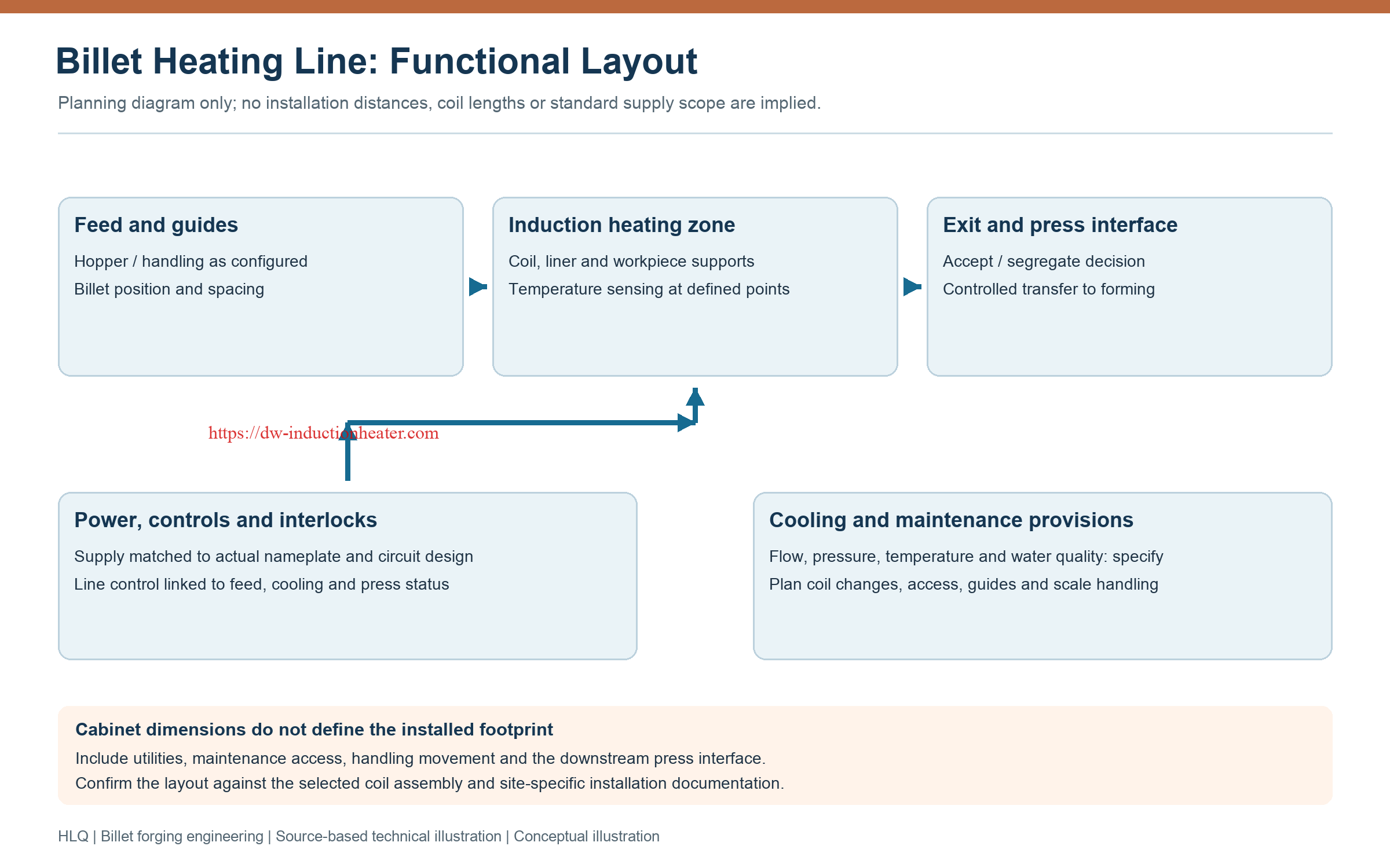
A billet-heating installation normally combines a matched induction power supply, a coil assembly, workpiece supports, material handling, cooling, temperature measurement and control functions. The installed scope depends on the workpiece and production process.
In through-heating, the relevant cross-section must reach an acceptable temperature distribution. In end heating, only the defined forming zone is heated. These duties require different coil geometries, thermal acceptance criteria and handling arrangements.
The broader relationship between heating and deformation is described in HLQ’s guide to induction forging and hot forming.
| Heating duty | Required result | Main design implication |
|---|---|---|
| Whole-billet through-heating | Acceptable surface, core and longitudinal temperature distribution | Coordinate frequency, power distribution and residence time |
| Bar-end or local heating | A defined hot zone with an appropriate transition to the unheated stock | Control active coil length, positioning and end effects |
| Continuous billet supply | Accepted billets delivered at a repeatable interval | Synchronize feeding, heating, measurement and the downstream press |
| Small-part or single-station heating | Repeatable heating of an individually positioned workpiece | Match the coil, fixture and complete handling cycle |
Working Principle
Alternating current in the induction coil creates a changing magnetic field. That field induces eddy currents in the conductive billet, and electrical resistance converts their energy into heat. Thermal conduction redistributes the heat during heating and any subsequent equalization period.
For magnetic materials, magnetic behavior also affects the heating process. Electrical resistivity and magnetic permeability change with temperature, so room-temperature assumptions should not be applied unchanged throughout a forging cycle.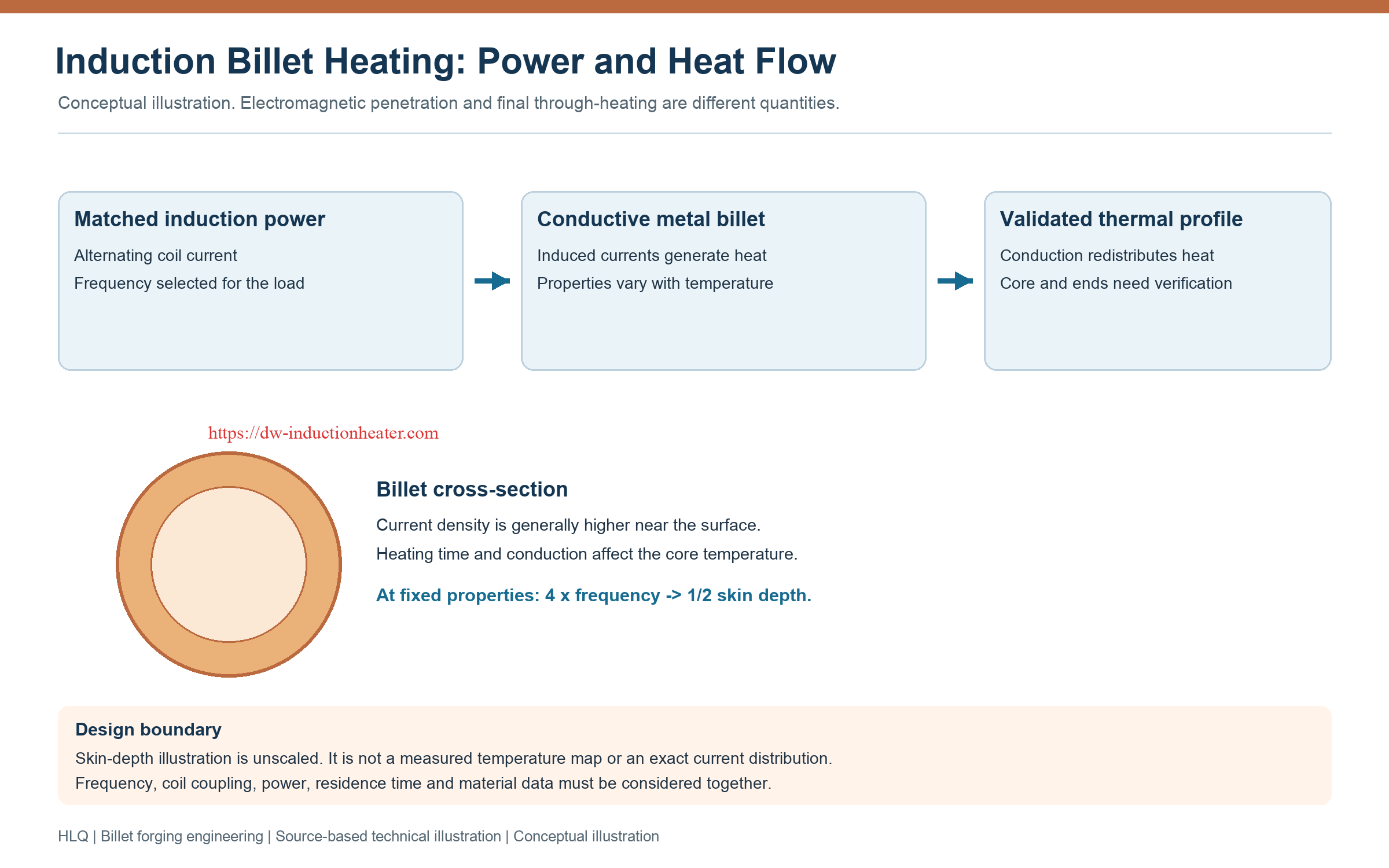
Skin Depth and Through-Heating
For a homogeneous conductor under the usual skin-depth approximation:
δ = √[ρ / (π × f × μ)]
| Symbol | Meaning | Unit |
|---|---|---|
| δ | Electromagnetic skin depth | m |
| ρ | Electrical resistivity | Ω·m |
| f | Operating frequency | Hz |
| μ | Magnetic permeability | H/m |
At fixed resistivity and permeability, skin depth varies with the inverse square root of frequency. The following values are mathematical ratios, not measured performance specifications for a furnace.
| Frequency relative to a reference | Skin depth relative to the reference |
|---|---|
| 0.5 × | Approximately 1.414 × |
| 1 × | 1 × |
| 2 × | Approximately 0.707 × |
| 4 × | 0.5 × |
Skin depth is not the final heated depth. A billet can continue heating internally through thermal conduction even where induced current density is lower. Conversely, a hot surface does not prove that the core has reached the required forging condition. See the dedicated explanation of skin effect in induction heating.
Why Coil Design Changes the Result
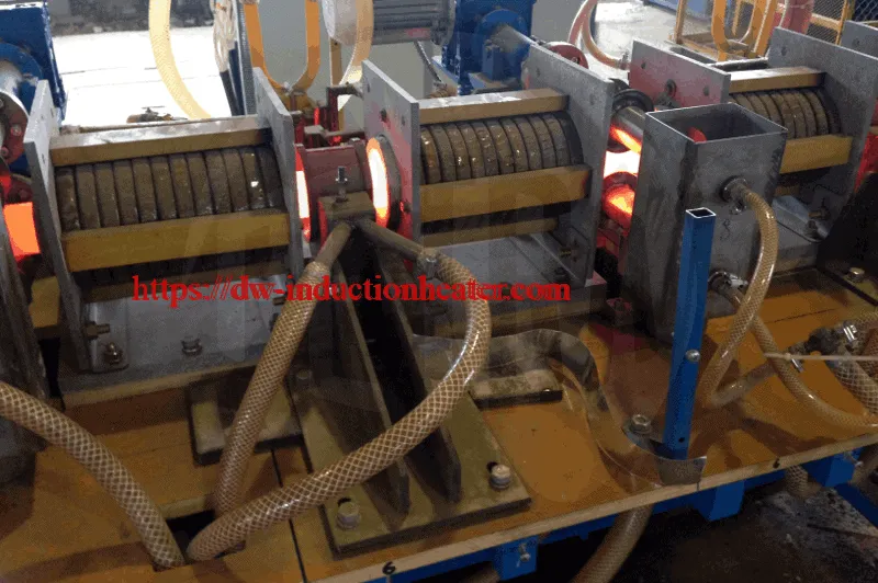
Coil bore, active length, turn arrangement, billet position and the required liner or fixture influence coupling and heat distribution. The coil also forms part of the electrical load seen by the power supply. Changing the workpiece or coil can therefore affect both heating performance and electrical matching.
Key Applications
Billet induction heating is relevant where metal stock must reach a controlled thermal condition immediately before forming. The same general technology can serve different operations, but the heating specification must follow the actual deformation process.
| Application | Heating objective | Engineering priority |
|---|---|---|
| Closed-die forging | Prepare a repeatable billet condition for the forming cycle | Thermal consistency, accepted-billet cadence and transfer time |
| Open-die forging | Heat the required stock section for deformation | Section size, internal temperature and handling sequence |
| Upsetting and heading | Heat the billet or selected end region | Hot-zone length, alignment and repeatable positioning |
| Small precision blanks | Heat individually supported workpieces | Fixture geometry, coil matching and measurement repeatability |
| Automated forging lines | Supply acceptable workpieces to the press | Feed control, temperature decisions, interruption handling and traceability |
Extrusion and rolling also use billet heating, but their temperature profiles and production interfaces should not be copied into a forging specification without review.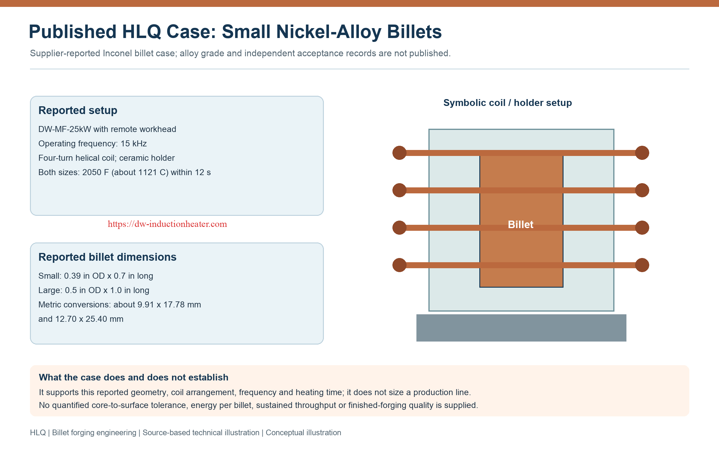
Suitable Materials and Industries
Induction heating applies to electrically conductive materials. Material suitability does not establish one universal frequency or forging temperature. The exact grade, starting condition, section size and approved forming procedure govern the process.
| Material group | Relevant application context | Main engineering consideration |
|---|---|---|
| Carbon and alloy steels | Forged mechanical parts, tools and general engineering components | Temperature-dependent properties, section size, scale and surface-to-core distribution |
| Stainless steels | Grade-dependent forged components | Magnetic behavior varies by grade; confirm heating response and the approved forging window |
| Aluminum alloys | Forged transport and industrial components | Alloy-specific upper temperature limits, uniformity and reliable temperature measurement |
| Copper, brass and bronze | Electrical, fluid-handling and general formed components | Electrical properties, coil coupling, alloy composition and heat transfer |
| Titanium alloys | Specialized forging and hot-forming applications | Grade-specific processing window, exposure and transfer conditions |
| Nickel alloys | Specialized high-temperature component blanks | Alloy identification, local overheating and validated internal temperature distribution |
These are application contexts, not claims of certification or documented deliveries to every industry. A temperature reported for an unspecified nickel or titanium alloy must not be reassigned to a named grade.
Technical Specifications
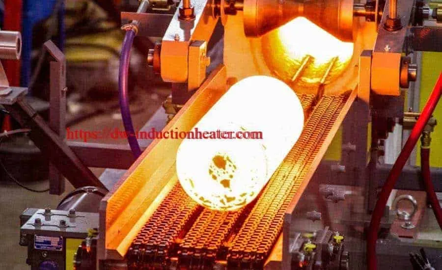
A billet-forging heater specification should distinguish the required process performance from the published equipment ratings. The following DW-MF values are listed in HLQ’s billet-heater and forge-furnace product tables.
| Model | Maximum input current | Listed host dimensions | Listed weight |
|---|---|---|---|
| DW-MF-200 | 320 A | 1000 × 800 × 1500 mm | 110 kg |
| DW-MF-250 | 400 A | 1000 × 800 × 1500 mm | 150 kg |
| DW-MF-300 | 480 A | 1000 × 800 × 1500 mm | 160 kg |
| DW-MF-400 | 640 A | 1500 × 800 × 2800 mm | 170 kg |
| DW-MF-500 | 800 A | 850 × 1700 × 1900 mm | 200 kg |
| DW-MF-600 | 960 A | 850 × 1700 × 1900 mm | 220 kg |
Dimension axes are not identified in the source. The source also qualifies weight by the extension dimensions. Confirm the scope of the listed weights and the complete installed mass before installation planning.
| Parameter | Published value | Engineering interpretation |
|---|---|---|
| Supply | Three-phase 380 V / 410 V / 440 V; 50/60 Hz | Confirm the supplied voltage configuration; automatic voltage switching is not established |
| Oscillating frequency | 0.5–20 kHz, interpreted from the source notation “0.5KHz^20KHz” | The source states that frequency is customized according to workpiece size |
| Duty cycle | 100%; 24-hour continuous operation described | Subject to the specified configuration, cooling and operating conditions |
| Cooling water pressure | 0.1 MPa < pressure < 0.3 MPa | Measurement location, flow and allowable temperature conditions require confirmation |
| Water hardness | Less than 50 | The unit and test basis are not stated; this is not a complete water-quality specification |
| Extension assembly | Customized to material and workpiece size | No universal extension dimensions or installed footprint are established |
Data boundary: this model table does not explicitly establish rated heating output, maximum billet diameter, guaranteed temperature uniformity or kg/h capacity. Model suffixes must not be used as verified output-power ratings.
The source can be reviewed under induction billet heater specifications.
Process Performance That Must Be Specified Separately
| Requirement | Definition needed | Acceptance evidence |
|---|---|---|
| Temperature window | Minimum and maximum at defined locations and process stages | Representative thermal validation |
| Temperature distribution | Allowed surface-to-core, end-to-middle and billet-to-billet variation | Measurement plan appropriate to the workpiece |
| Production rate | Accepted billets per hour or accepted mass per hour | Sustained production trial including normal handling |
| Transfer condition | Maximum delay and acceptable press-entry temperature | Validated heating-to-forging sequence |
| Energy use | Measurement boundary and accepted production basis | Metered energy over a defined operating period |
| Interruption response | Behavior during feed faults, press stops and restart | Verified control and material-handling sequence |
Recommended Model Selection
The best candidate is the system that satisfies the complete heating duty and production interface with verified operating margins. Selecting the largest model or the lowest listed current is not a substitute for defining that duty.
| Process requirement | Configuration to evaluate | Evidence needed before selection |
|---|---|---|
| Small, individually supported billets | A matched generator, workhead, coil and fixture | Representative heating trials; the published DW-MF-25kW case is a reference for its stated workpieces only |
| Repeated whole-billet heating | An inline heating arrangement with controlled feeding | Required absorbed heat rate, verified output capability and sustained temperature performance |
| Large sections needing longer equalization | Frequency and coil-zone arrangements assessed for through-heating | Validated internal temperature profile and actual residence-time requirement |
| Localized upsetting or heading | An end-heating coil and repeatable positioning system | Heated-zone length, transition temperature and complete cycle time |
| Frequent material or size changes | Defined coil and recipe changeover arrangements | Separate qualified settings for each approved product family |
For the listed DW-MF-200 through DW-MF-600 models, compare the calculated duty with confirmed equipment ratings and application trials. Input-current data supports electrical planning, but it does not determine the achievable billet diameter or production rate by itself.
Keep Three Time Quantities Separate
- Heating residence time: how long a billet remains in the effective heating process.
- Discharge interval: the time between successive accepted billets leaving the line.
- Complete production cycle: loading, heating, handling, transfer, forging and any required recovery actions.
A continuous line can contain several billets simultaneously. Its discharge interval therefore need not equal an individual billet’s heating residence time.
Process Workflow
- Identify incoming stock: verify grade, billet dimensions and starting condition against the approved recipe.
- Confirm system readiness: check cooling, power availability, measurement, guides and required interlocks.
- Feed and position: control billet alignment, spacing and movement through the active heating zone.
- Heat and equalize: apply the validated power and motion sequence to achieve the required temperature distribution.
- Measure and decide: compare the measured exit condition with the approved acceptance criteria.
- Transfer or segregate: send accepted billets to forming and handle out-of-window material according to the approved procedure.
- Forge and record: maintain the specified transfer interval and capture the required production records.
HLQ’s original equipment descriptions discuss hopper or bowl feeding, pinch rollers, chain-driven handling and pneumatic pushers. They also describe water-cooled rails or ceramic liners through the coil bore. These are available design approaches described on the site, not a statement that every machine includes every arrangement.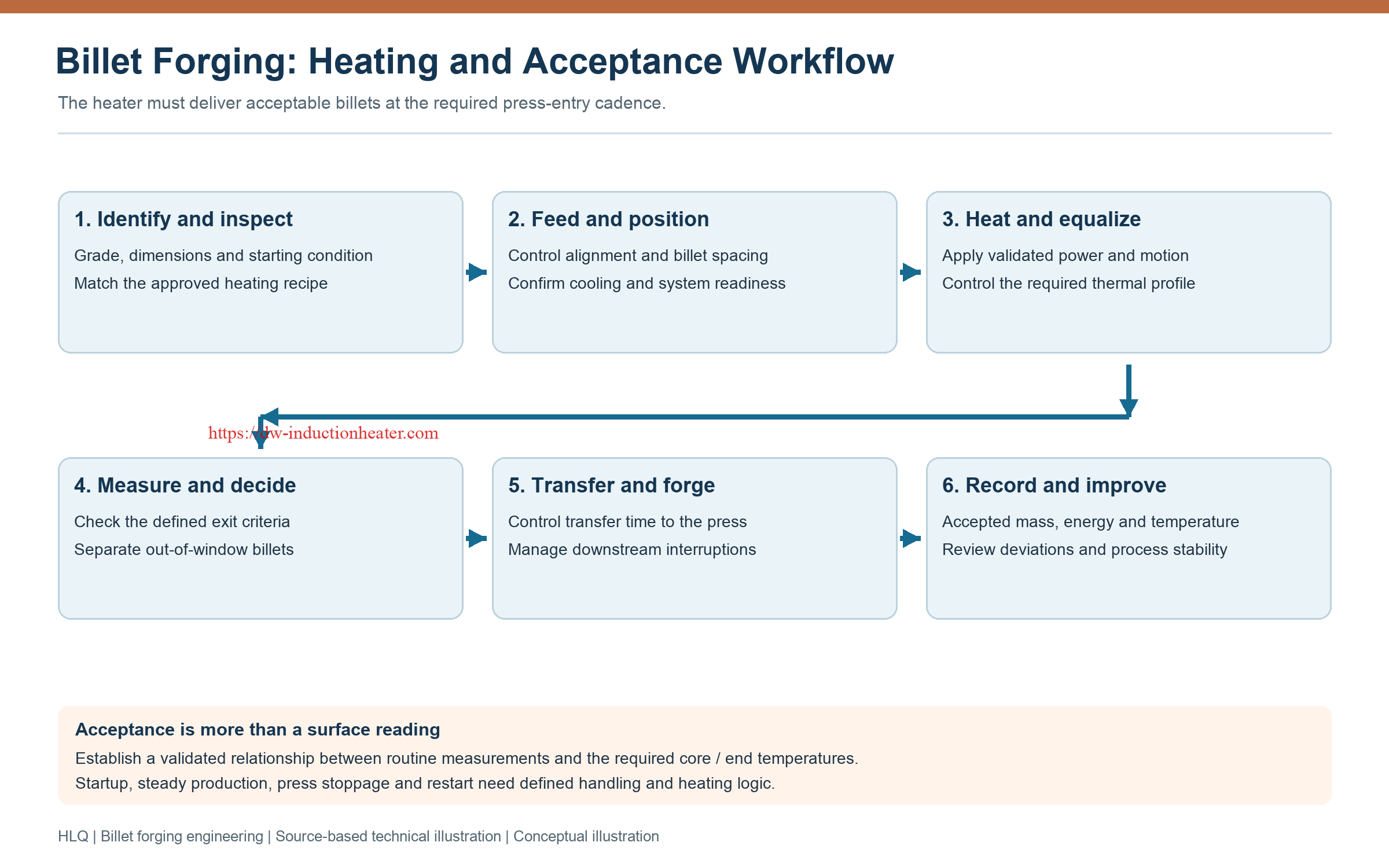
| Line state | Process concern | Required definition |
|---|---|---|
| Startup | Initial equipment and billet temperatures differ from steady production | Startup recipe and first-billet acceptance |
| Steady production | Repeatable loading and heating must be maintained | Feed cadence, power control and acceptance monitoring |
| Downstream press stop | Billets may remain hot for longer than intended | Approved hold, discharge or segregation response |
| Feed interruption | Load and residence conditions change | Coordinated power and handling response |
| Restart | Interrupted billets may have a different thermal history | Material disposition and validated restart sequence |
Common Problems and Solutions
The following table gives engineering investigation paths. It is not a diagnosis of faults in a particular installation.
| Observed condition | Possible contributing factors | Engineering response |
|---|---|---|
| Hot surface and insufficient core temperature | Unsuitable frequency, section size, power distribution or residence time | Verify the internal profile and review the complete heating cycle |
| Overheated billet ends | End effects, coil geometry, positioning or excessive exposure | Map the longitudinal profile and revise the validated coil or recipe |
| Billet-to-billet temperature variation | Stock variation, starting temperature, spacing, feed motion or measurement conditions | Check incoming material, motion repeatability and sensor setup |
| Temperature appears correct but forging behavior varies | Surface measurement does not represent core condition; transfer delays or material variation | Validate press-entry conditions and the relationship between routine readings and internal temperature |
| Excessive oxidation or scale | Temperature, exposure time, atmosphere or interrupted production | Review the grade-specific thermal history and interruption strategy |
| Cooling alarm or component overheating | Restricted flow, unsuitable water condition or cooling-system faults | Follow the prescribed stop procedure and restore confirmed operating conditions |
| Billets stall in the line | Misalignment, worn guides, dimensional variation or unsuitable clearances | Inspect handling equipment and stock under the required isolation procedure |
| High energy per accepted billet | Idle losses, rejects, poor matching or inconsistent operation | Measure energy and accepted output over the same defined period |
Engineering Selection Guide
1. Calculate the Useful Thermal Duty
Use material-specific enthalpy data over the actual temperature interval. A single room-temperature heat-capacity value may not adequately represent a large temperature rise or a transformation range.
| Quantity | Relationship | Units and limits |
|---|---|---|
| Energy absorbed by one billet | Q = m × Δh | m in kg and Δh in kJ/kg give Q in kJ |
| Sensible enthalpy increase | Δh = integral of cp(T) dT | Use grade-specific data; include relevant transformation effects in the complete enthalpy change |
| Useful continuous heating power | Puseful = ṁ × Δh | ṁ in kg/s and Δh in kJ/kg give power in kW |
| Preliminary electrical demand | Pelectrical = Puseful / η | η must have a defined system boundary; include auxiliary demand consistently |
| Steady-motion residence time | tres = Leffective / v | Heated travel length in m divided by speed in m/s; indexed lines require their actual motion sequence |
| Required discharge interval | τ = 3600 / N | N is required accepted billets per hour; τ is seconds per accepted billet |
| Measured specific electrical energy | e = Emetered / Maccepted | kWh divided by accepted kg; define startup, idle and auxiliary-energy treatment |
These relationships support a preliminary design. They do not supply an assumed efficiency, substitute for temperature-distribution analysis or create a guaranteed equipment capacity.
2. Match Frequency and Coil Geometry
Assess the billet cross-section together with temperature-dependent electrical properties, the required heating time and the acceptable thermal gradient. Coil bore must accommodate the billet, dimensional variation, supports and any liner or fixture.
Turn arrangement and active length influence heating distribution, while the assembled coil must remain compatible with the generator and matching circuit. Review induction heating coil design as an application-specific engineering task.
| Design item | Required input | What to verify |
|---|---|---|
| Coil opening | Maximum stock size, liner and support arrangement | Clearance, alignment and coupling |
| Active heating length | Thermal duty, motion profile and required equalization | Temperature profile along the billet |
| Turn arrangement | Workpiece shape and desired heating distribution | End effects and local overheating |
| Electrical matching | Actual coil and workpiece load | Generator operating limits and stable power delivery |
| Workpiece supports | Billet mass, temperature and movement | Wear, friction, alignment and maintenance access |
| Cooling | Heat rejection and component requirements | Flow, pressure, temperature, water quality and interlocks |
3. Validate Measurement and Transfer
A pyrometer reports a surface-related temperature under its measurement conditions. Surface condition, emissivity settings, viewing geometry and field of view can affect the result. Routine measurement should be linked to a validated thermal profile for the actual billet.
Specify whether the acceptance temperature applies at the coil exit, after equalization or at press entry. Transfer time is part of the thermal process, because a billet can satisfy an exit criterion and still reach the press outside its approved forming window.
4. Define the Installed Layout
Plan feeding, heating, sensing, segregation and transfer together with the power cabinet, cooling system, coil-change access and maintenance routes. Published host dimensions do not define the installed line footprint.
5. Agree on Acceptance Tests
- Identify the material grade, representative billet sizes and starting conditions.
- Define temperature acceptance at the required surface, core and longitudinal locations.
- Verify sustained accepted output with the actual feeding and transfer sequence.
- Measure electrical energy using an agreed boundary and production basis.
- Check temperature decisions, segregation functions and specified protective interlocks.
- Verify the approved response to interruption, changeover and restart.
Advantages and Limitations
| Potential advantage | Engineering basis | Limitation or condition |
|---|---|---|
| Controlled heating near the forming operation | Power and residence time can be coordinated with production | The thermal profile and press-entry condition still require validation |
| Application-specific heating zones | Coil geometry can be designed around the required region | Different parts may require different coils and recipes |
| Automation potential | Feeding, measurement and discharge can be integrated | Supplied functions and press interfaces must be defined |
| Flameless heating at the induction zone | Electrical energy is coupled into the conductive workpiece | Hot surfaces, electrical equipment and moving stock still require appropriate controls |
| Potential reduction in unnecessary heat exposure | Heating can be matched to the workpiece and schedule | Oxidation and scale depend on material, temperature, time and atmosphere |
| Potential energy improvement | Duty-specific heating and production control can reduce avoidable losses | Savings must be measured against a defined, comparable baseline |
A meaningful comparison uses the same alloy, billet geometry, entry and exit conditions, accepted output and energy-measurement boundary. Further context is available in the HLQ comparison of induction heating vs gas furnace for billet forging.
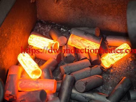
Real Engineering Case Study
Published HLQ Case: Small Nickel-Alloy Billets
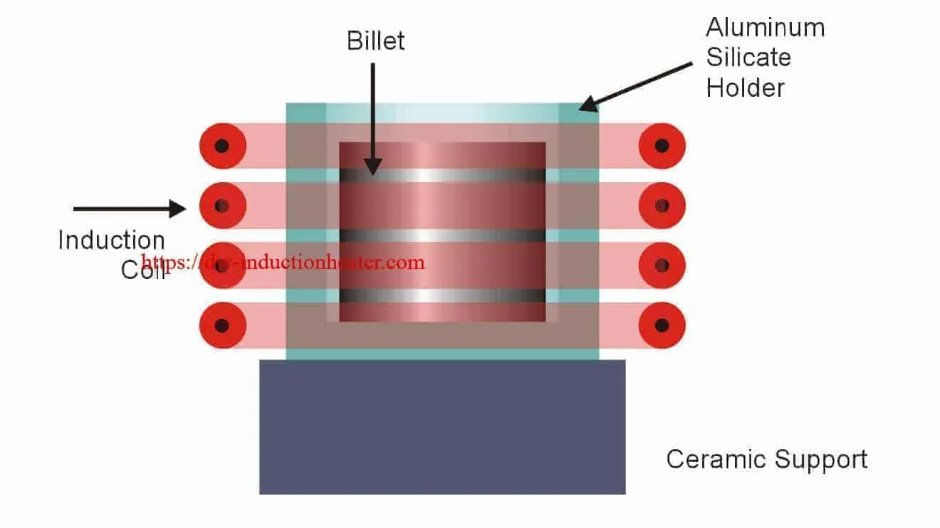
HLQ publishes an induction forging billet case study involving billets identified as Inconel, with the exact alloy grade not stated. Two billet sizes were heated in ceramic holders using a DW-MF-25kW system and an application-specific four-turn helical coil.
The following values are supplier-reported case data. They are not independently verified acceptance results or a universal forging recipe.
| Parameter | Published case information |
|---|---|
| Objective | Heat small nickel-alloy billets before forging |
| Material | Inconel; specific grade not stated |
| Small billet | 0.39 in outside diameter × 0.7 in long; approximately 9.91 × 17.78 mm |
| Large billet | 0.5 in outside diameter × 1.0 in long; 12.70 × 25.40 mm |
| Small holder dimensions | 1.0 in OD × 0.7 in ID × 1.4 in long |
| Large holder dimensions | 1.25 in OD × 0.87 in ID × 1.37 in long |
| Equipment | DW-MF-25kW induction system with a remote workhead |
| Operating frequency | 15 kHz |
| Coil | Four-turn helical coil designed for the application |
| Reported temperature | 2050°F, approximately 1121°C |
| Reported heating time | Both billet sizes reached the stated temperature within 12 seconds |
| Reported outcome | Uniform and repeatable heating, described qualitatively |
Engineering Lessons from the Case
Fixture dimensions matter: the coil must accommodate the holder, not just the bare billet. The published holders are substantially larger than the workpieces they support.
Frequency is application-specific: the reported 15 kHz operating point belongs to these small billets and this coil arrangement. It should not be transferred directly to a large steel billet line.
Heating time does not define production capacity: the 12-second value does not include a documented loading, unloading, transfer or forging sequence. It therefore cannot establish sustained accepted output.
What the Published Case Does Not Establish
- The exact nickel-alloy grade or its approved forging window.
- A quantified surface-to-core temperature tolerance.
- Electrical energy consumed per billet or overall heating efficiency.
- Sustained production rate with normal material handling.
- Mechanical-property or finished-forging acceptance results.
Its value is a traceable example of matching billet geometry, fixture, coil, frequency and heating time. Scaling requires a new thermal and electromagnetic assessment.
Why Choose HLQ?
HLQ publishes billet-heating equipment data, forging application descriptions, coil information and individual heating cases. These resources provide a basis for developing a configuration around the actual workpiece rather than relying only on a broad catalogue description.
The published billet-heater range describes customized extension assemblies, feeding arrangements, temperature measurement and workpiece selection. The appropriate supplied functions should be defined in the equipment specification and checked during acceptance.
For an engineering-led evaluation, the useful comparison is the proposed configuration against a written process requirement: achieved temperature distribution, sustained accepted output, measured energy use, utility requirements and verified control functions. This page does not add unverified certification, service-life or universal energy-saving claims.
6 Core FAQs
1. How do you calculate induction heater power for billet forging?
Start with the required mass flow and grade-specific enthalpy increase: useful heating power equals mass flow multiplied by specific enthalpy change. Convert that useful duty into electrical demand using a justified efficiency and a clearly defined system boundary. Then verify the thermal profile and required output through application design and trials.
2. Which induction frequency is best for billet forging?
There is no single best frequency for all billets. Material properties, section size, required heating time, coil design and temperature-distribution limits must be considered together. Lower frequency increases skin depth at unchanged material properties, but skin depth alone does not establish successful through-heating.
3. Can a surface pyrometer confirm that the billet core is ready for forging?
Not by itself. A surface reading must be related to a validated internal temperature profile for the actual material, geometry and heating cycle. The measurement location, surface condition, emissivity setup and transfer interval also matter.
4. Does a DW-MF model number define its output power or production capacity?
Not unless the applicable specification explicitly defines it that way. The cited DW-MF-200 through DW-MF-600 table lists input current and other equipment data but does not establish rated heating output or guaranteed kg/h. Use confirmed ratings and representative process evidence.
5. Does induction heating eliminate oxidation and guarantee energy savings?
No universal result is established. Oxidation depends on the material, temperature, exposure time and atmosphere. Energy comparisons require equivalent accepted output and thermal conditions, with consistent treatment of startup, idle operation and auxiliary equipment.
6. What information is needed to select a billet-forging heating system?
Define material grade, billet cross-section and length, mass, starting temperature, approved forging window, internal temperature requirements, accepted production rate and transfer time. Add available electrical supply, cooling conditions, feeding method, layout constraints, changeover needs and acceptance criteria.