
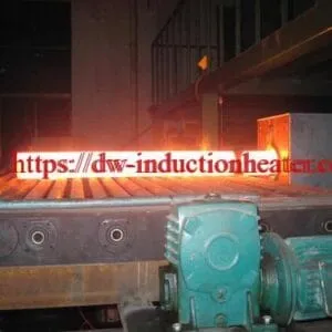
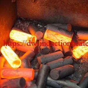
Induction Billet Heater
Induction Billet Heater for Steel and Nonferrous Metal Hot Forming
Quick Answer
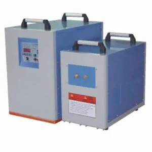
An induction billet heater uses an alternating magnetic field to generate heat inside a conductive metal billet before hot forming. The HLQ product page lists six models, DW-MF-200 through DW-MF-600, for billet and bar heating applications involving steel, iron, copper, brass, bronze and aluminum alloys.
Model selection requires the material grade, billet dimensions, starting and target temperatures, temperature uniformity requirement and production rate. The published model table does not establish rated output power, billet size capacity or hourly throughput.
Table of Contents
- Quick Answer
- What is an Induction Billet Heater?
- Key Applications
- Suitable Materials
- Working Principle
- Technical Specifications
- Recommended Model Selection
- Process Workflow
- Common Problems and Solutions
- Engineering Selection Guide
- Advantages and Limitations
- Why Choose HLQ?
- 6 Core FAQs
What is an Induction Billet Heater?
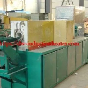
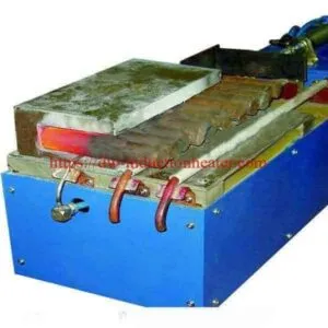
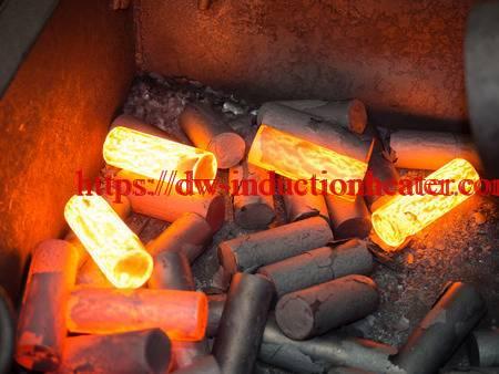
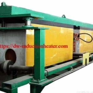
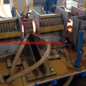
An induction billet heater combines an induction power supply, a heating coil and a workpiece handling arrangement to prepare billets or slugs for a subsequent forming operation. Through-heating aims to bring the required billet cross-section into an acceptable forming temperature window.
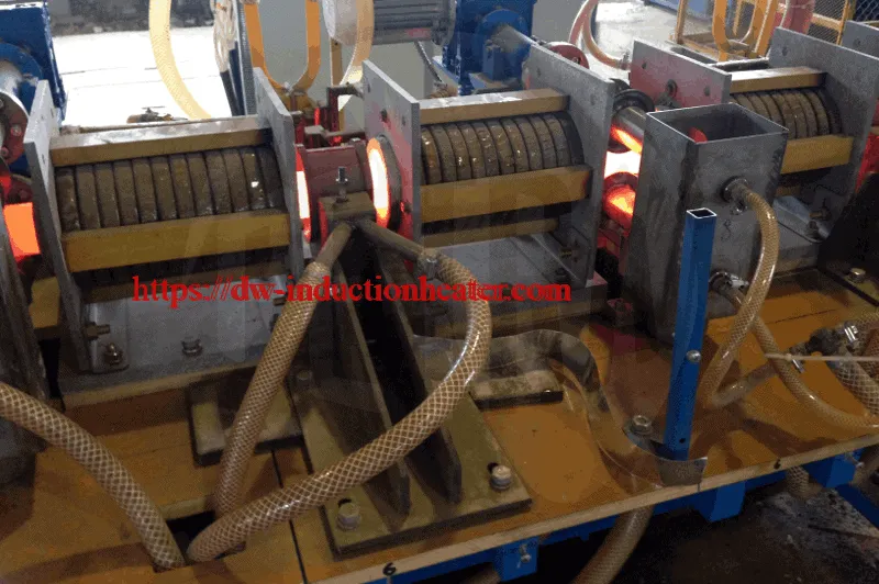
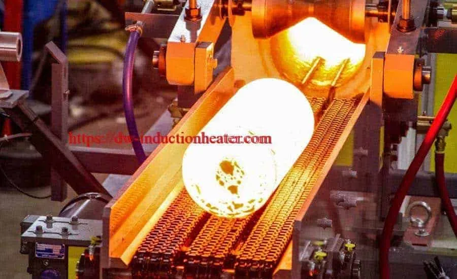
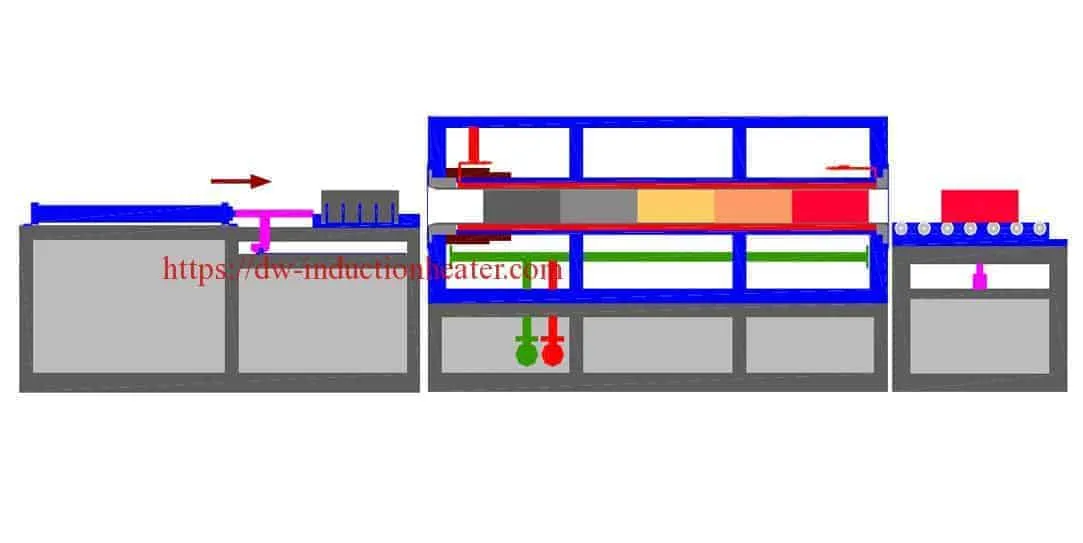
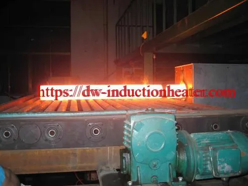
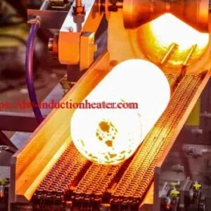
The original product description discusses feeding short billets from a hopper or bowl, moving them through the coil and discharging the heated workpieces. The appropriate feeding mechanism, coil assembly and temperature measurement arrangement depend on the billet and production process.
For the underlying technology, see induction heating principles.
Key Applications
The principal application described on this product page is billet, slug or bar heating before hot forming. A heating line must deliver an acceptable temperature distribution while remaining synchronized with the downstream operation.
- Steel and iron billet preparation for suitable hot forming processes.
- Copper, brass and bronze stock heating with a material-specific recipe.
- Aluminum alloy billet heating within the alloy’s approved processing window.
- Repeated billet heating where feeding, measurement and discharge functions are configured for the production sequence.
Related process information is available under induction forging and hot forming.
Suitable Materials
The original page identifies the following material groups. Inclusion in the list does not establish that one coil or one operating recipe is suitable for every grade and billet size.
| Material group | Selection consideration | Information required |
|---|---|---|
| Steel and iron | Electrical and magnetic properties change with temperature; heating time and frequency affect the temperature profile. | Grade, section size, target temperature and acceptable surface-to-core difference. |
| Copper | Coil coupling and electrical properties must be considered for the actual workpiece. | Grade, geometry, starting temperature and production rate. |
| Brass and bronze | Alloy composition determines the appropriate processing window. | Alloy designation and approved forming conditions. |
| Aluminum alloys | The heating recipe must respect the specific alloy’s temperature limits. | Alloy, billet dimensions, temperature window and transfer time. |
Working Principle
Alternating current in the induction coil creates a changing magnetic field. This field induces eddy currents in the conductive billet, and electrical resistance converts their energy into heat. Thermal conduction redistributes heat within the billet during heating and any subsequent equalization period.
Current distribution is affected by the skin effect. For a homogeneous conductor under the usual skin-depth approximation:
δ = √[ρ / (π f μ)]
- δ: electromagnetic skin depth, in metres.
- ρ: electrical resistivity, in ohm-metres.
- f: frequency, in hertz.
- μ: magnetic permeability, in henries per metre.
At unchanged material properties, increasing frequency reduces skin depth. Skin depth is not the same as the final heated depth or a guarantee of core temperature. Billet geometry, temperature-dependent properties, power distribution and residence time also matter.
See the explanation of skin effect in induction heating for additional context.
Technical Specifications
The following values reproduce the published product data. They are source-listed specifications, not independently measured performance results.
| Parameter | DW-MF-200 | DW-MF-250 | DW-MF-300 | DW-MF-400 | DW-MF-500 | DW-MF-600 |
|---|---|---|---|---|---|---|
| Maximum input current | 320 A | 400 A | 480 A | 640 A | 800 A | 960 A |
| Host dimensions, as grouped in the source | 1000 × 800 × 1500 mm | 1500 × 800 × 2800 mm | 850 × 1700 × 1900 mm | |||
| Listed weight | 110 kg | 150 kg | 160 kg | 170 kg | 200 kg | 220 kg |
| Parameter | Published information | Qualification |
|---|---|---|
| Input supply | Three-phase; 380 V / 410 V / 440 V; 50/60 Hz. | Confirm the supplied voltage configuration. The list does not establish automatic switching between voltages. |
| Oscillating frequency | Original notation: 0.5KHz^20KHz; interpreted as 0.5–20 kHz. Frequency is customized according to workpiece size. | Confirm the selected operating frequency and adjustment range for the actual system. |
| Duty cycle | 100%; described as suitable for 24-hour continuous operation. | This is the published rating, subject to the specified operating and cooling conditions. |
| Cooling water pressure | 0.1 MPa < water pressure < 0.3 MPa. | The source uses strict inequalities and does not specify the pressure measurement location. |
| Cooling water hardness | Water hardness < 50. | The source does not state a unit or test basis. Do not interpret this number as a complete water treatment specification. |
| Extension assembly | Customized according to the material and dimensions of the heated workpieces. | No standard extension dimensions are published. |
| Weight qualification | The source adds that weight depends on extension dimensions. | Confirm the scope of the listed weights and the complete installed equipment weight. |
| Power electronics | IGBT type is listed in the original feature table. | The page does not provide a circuit topology, efficiency curve or power quality test result. |
Data boundaries: The dimension axes are not identified in the source. The page does not specify rated heating output, maximum billet diameter, billet length range, heating temperature range, guaranteed temperature uniformity, cooling flow rate or production capacity. Model suffixes must not be treated as verified output power ratings.
Recommended Model Selection
Select a candidate model from the required heating duty and verified equipment capability. The published input-current values support an initial electrical comparison, but they do not establish which model can heat a particular billet at a specified production rate.
| Selection step | Required evidence | Decision supported |
|---|---|---|
| Define the billet | Material grade, cross-section, length, mass and dimensional variation. | Coil opening, handling arrangement and material properties. |
| Define the thermal duty | Starting temperature, exit temperature window and required temperature distribution. | Heating energy, residence time and frequency assessment. |
| Define production demand | Billets per minute or kg/h, downstream cycle and interruption pattern. | Required sustained heating rate and line synchronization. |
| Compare candidate models | Confirmed output rating, coil design, application calculations and representative trials. | Selection among DW-MF-200, 250, 300, 400, 500 and 600. |
| Verify installation | Supply configuration, installation drawing, cooling requirements and equipment mass. | Site compatibility and final configuration. |
Related equipment is listed in the medium frequency induction heating equipment category. Specifications from another product must not be transferred to these models without confirmation.
Process Workflow
- Verify incoming stock: Check material identity, billet dimensions and consistency with the approved recipe.
- Check system readiness: Verify cooling, handling equipment, measurement equipment and required interlocks.
- Feed the billets: Present workpieces to the coil using the configured feeding mechanism.
- Apply the heating recipe: Control power and residence time to achieve the validated temperature distribution.
- Measure the exit condition: Compare the measured temperature with the approved acceptance window.
- Transfer or segregate: Move acceptable billets to forming and separate out-of-window billets under the approved procedure.


The original page describes automatic feeding, temperature measurement, workpiece selection and discharge. Their implementation and inclusion in a particular supply configuration require confirmation.
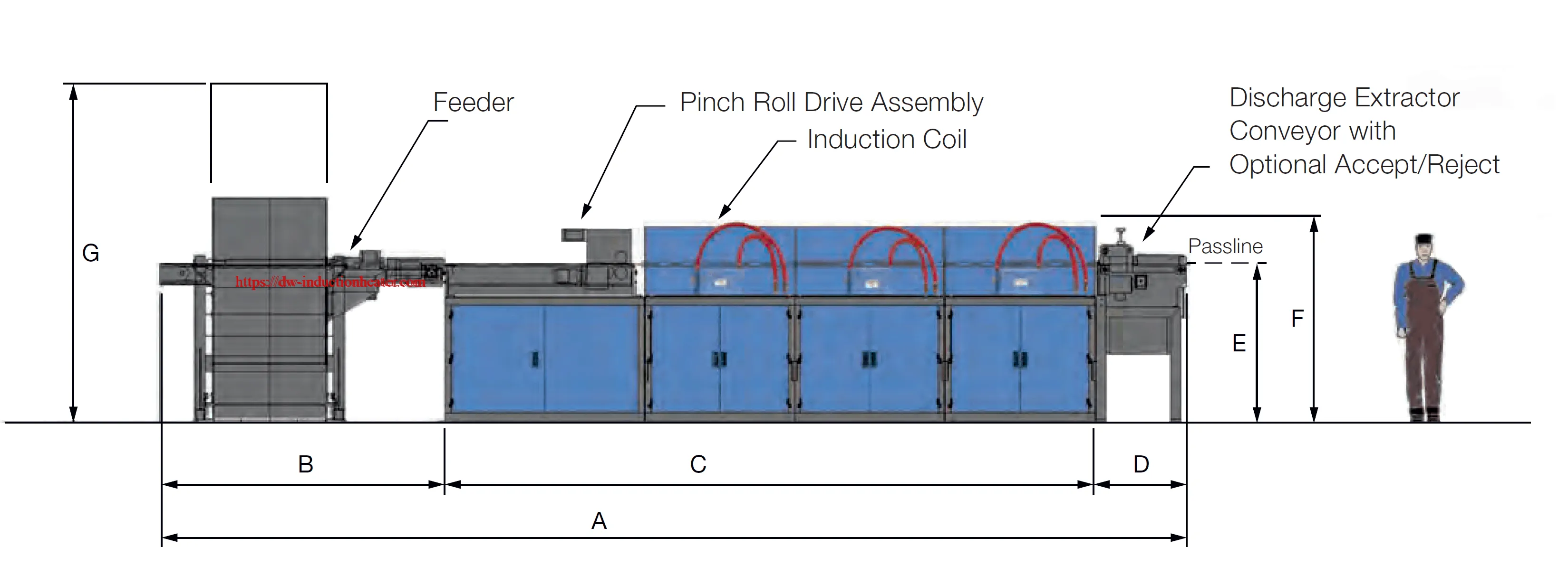
The original description also mentions pinch rollers, chain-driven handling or pneumatic pushers, with water-cooled rails or ceramic liners through the coil bore. These are described handling arrangements, not a statement that every model includes all of them.
Common Problems and Solutions
The following table gives general engineering checks. It is not a record of faults observed on the listed models. Inspection and adjustment must follow the equipment operating procedure.
| Observed condition | Possible factors | Engineering response |
|---|---|---|
| Hot surface with an insufficiently heated core | Frequency, section size, power distribution or residence time may be unsuitable. | Validate the internal temperature profile and review the coil and heating cycle. |
| Billet-to-billet exit temperature variation | Variation in stock size, starting temperature, feed spacing or measurement conditions. | Check incoming stock consistency, handling repeatability and temperature measurement setup. |
| Local overheating | Coil coupling, workpiece position or heating distribution may be uneven. | Review alignment and coil design; verify the temperature profile before changing the recipe. |
| Cooling alarm | Restricted flow, unsuitable pressure, excessive water temperature or a cooling-system fault. | Follow the prescribed stop procedure and restore the required cooling conditions before restarting. |
| Billets stall or move unevenly | Misalignment, damaged guides, unsuitable clearances or inconsistent billet geometry. | Isolate the equipment as required and inspect the feed mechanism, guides and stock dimensions. |
| Unexpectedly high energy per accepted billet | Idle time, rejected billets, transfer losses or poor matching of coil and duty. | Measure energy and accepted production over a defined period, then review the complete process. |
Engineering Selection Guide
A complete heating specification should define the billet, thermal acceptance criteria, required production rate and site utilities. The host cabinet dimensions alone do not establish the installed line footprint.
| Quantity | Relationship | Use and limitation |
|---|---|---|
| Billet heating energy | Q = m × integral of cp(T) dT between starting and target temperatures. | Estimates sensible heat using grade-specific material data. Include transformation energy where relevant. |
| Useful heat rate | Puseful = mass flow rate × required specific enthalpy increase. | Relates production demand to heat absorbed by the billets. Electrical demand also includes system losses. |
| Continuous-line residence time | t = effective heated travel length / feed speed. | Applies to steady motion; indexed feeding requires its actual motion cycle. |
| Specific electrical energy | Measured electrical energy / accepted processed mass. | Allows comparison in kWh/kg when the measurement boundary and production conditions are consistent. |
| Temperature acceptance | Specified surface, core and longitudinal temperature limits. | An exit surface reading alone does not verify the entire internal temperature distribution. |
The coil opening, coupling gap, heated length, lining and workpiece supports must suit the actual billet. Explore related induction heating coils while treating the final coil as an application-specific component.
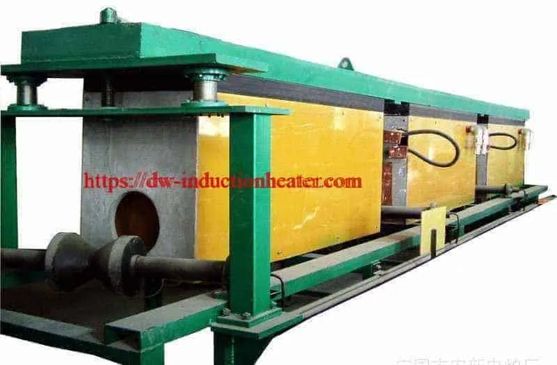
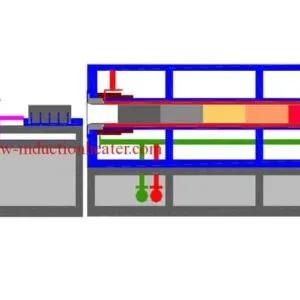
The original description discusses arrangements with four or five coils in series and an overall coil length of 5 m or more for some high-volume, large-section duties. This is a general configuration example; it is not the published standard length of any listed DW-MF model.
Original Layout Illustration

Advantages and Limitations
Potential Advantages
- Electrical energy is coupled into the conductive workpiece without a burner flame at the induction heating zone.
- Power and feed control can support repeatable heating when the process is properly matched and validated.
- Feeding, temperature measurement and discharge can be integrated into the production sequence.
- Coils and handling arrangements can be adapted to the specified billet and process.
Further process context is available in the overview of advantages of induction heating.
Limitations and Conditions
- Uniform through-heating requires a suitable combination of frequency, coil design, power distribution and time.
- Changing material grade or billet dimensions may require a different recipe or coil.
- Oxidation depends on temperature, exposure time, material and atmosphere; induction does not guarantee an oxide-free surface.
- Cooling requirements must be fully specified and maintained.
- Energy savings require a defined baseline and comparable production measurements. No universal saving percentage is established here.
- Electrical, thermal and mechanical hazards require the prescribed protective measures and operating procedures.
Why Choose HLQ?
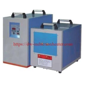
The published HLQ offering provides six identified DW-MF models and describes customization of functions and the extension assembly according to the heating task. The page also describes an integrated equipment arrangement and an operating panel that displays machine status.
Listed protective indications include overcurrent, overvoltage, overheating and insufficient cooling water. Their actual thresholds, interlock logic and supplied scope should be verified in the equipment documentation.
A practical evaluation should compare the proposed configuration with a written process specification and representative billet trials. Relevant acceptance evidence includes the achieved temperature distribution, sustained production rate, measured energy consumption and verified operation of the supplied handling and protection functions.
6 Core FAQs
1. What does an induction billet heater do?
It heats a conductive metal billet or slug before a forming operation. The process must deliver the required temperature distribution throughout the portion of the workpiece that will be formed.
2. Which materials are listed for this HLQ billet heater?
The original page identifies steel, iron, copper, brass, bronze and aluminum alloys. Compatibility with a particular grade and billet geometry requires a matched coil, power supply configuration and validated heating recipe.
3. Does DW-MF-200 mean a verified 200 kW heating output?
The product page does not explicitly define the model suffix as rated output power. It lists maximum input current and other shared specifications. Obtain the confirmed output rating and operating conditions before using the model designation in an energy or capacity calculation.
4. What frequency is published for the equipment?
The original table uses the notation “0.5KHz^20KHz,” interpreted here as 0.5–20 kHz, and says frequency is customized according to workpiece size. Confirm the actual selected frequency and available adjustment range for the supplied equipment.
5. Can the heater operate continuously?
The published table states a 100% duty cycle and describes 24-hour continuous operation. This rating depends on maintaining the specified operating conditions, including suitable cooling. The page does not provide all cooling flow and temperature requirements.
6. How should the correct model be selected?
Define the material grade, billet dimensions and mass, starting and target temperatures, acceptable temperature variation, required production rate and site utilities. Compare the resulting duty with confirmed equipment ratings and representative heating trials. The published table alone cannot establish a guaranteed billet size or kg/h capacity.