
Case Study: Optimization of Bearing Assembly and Disassembly Using Induction Heating Technology
Executive Summary
This case study examines how Volvo Construction Equipment’s manufacturing facility in Eskilstuna, Sweden implemented an induction heating system to optimize their bearing assembly and disassembly processes. The transition from traditional flame heating methods to precision induction technology resulted in a 68% reduction in assembly time, 42% energy savings, and virtually eliminated bearing damage during installation. The project achieved ROI in 9.3 months and significantly improved production quality metrics.
Background
Company Profile
Volvo Construction Equipment (Volvo CE) produces heavy machinery components requiring precise bearing fits for optimal performance and durability. Their Eskilstuna facility specializes in transmission assemblies for wheel loaders and articulated haulers.
Challenge
Prior to implementation, Volvo CE utilized the following bearing installation methods:
- Gas flame heating for large bearings
- Oil baths for medium bearings
- Mechanical pressing for smaller components
These methods presented several challenges:
- Inconsistent heating leading to dimensional variations
- Workplace safety hazards from open flames and hot oil
- Environmental concerns from oil disposal
- Frequent bearing damage during installation
- Lengthy heating cycles impacting production flow
Implementation of Induction Heating System
System Selection and Specifications
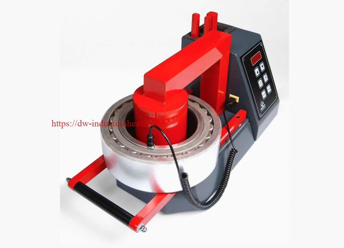
After evaluating multiple vendors, Volvo CE selected an EFD Induction MINAC 18/25 system with the following specifications:
Table 1: Induction Heating System Specifications
| Parameter | Specification | Notes |
|---|---|---|
| Model | MINAC 18/25 | Mobile induction heater |
| Power Output | 18 kW | Variable frequency |
| Input Voltage | 400V, 3-phase | Compatible with factory supply |
| Frequency Range | 10-40 kHz | Automatically optimized |
| Duty Cycle | 100% @ 18 kW | Continuous operation capability |
| Cooling System | Water-cooled | Closed-loop chiller |
| Control Interface | PLC with touchscreen | Temperature and time control |
| Temperature Range | 20-350°C | Precision control ±3°C |
| Heating Coils | 5 interchangeable | Sized for bearing range |
| Temperature Monitoring | Infrared pyrometer | Non-contact measurement |
Process Implementation
The implementation focused on bearings used in gearbox assemblies with the following characteristics:
Table 2: Bearing Specifications in Application
| Bearing Type | Inner Diameter (mm) | Outer Diameter (mm) | Weight (kg) | Interference Fit (μm) | Required Expansion (mm) |
|---|---|---|---|---|---|
| Cylindrical Roller | 110 | 170 | 4.2 | 40-60 | 0.12-0.18 |
| Spherical Roller | 150 | 225 | 8.7 | 50-75 | 0.15-0.23 |
| Angular Contact | 85 | 130 | 2.1 | 30-45 | 0.09-0.14 |
| Tapered Roller | 120 | 180 | 5.3 | 45-65 | 0.14-0.20 |
| Deep Groove Ball | 95 | 145 | 2.8 | 25-40 | 0.08-0.12 |
Data Collection and Analysis
Heating Profile Analysis
Engineers developed optimized heating profiles for each bearing type:
Table 3: Optimized Heating Profiles
| Bearing Type | Target Temp (°C) | Ramp Rate (°C/s) | Hold Time (s) | Total Cycle (s) | Power Setting (%) |
|---|---|---|---|---|---|
| Cylindrical Roller | 120 | 4.0 | 15 | 45 | 65 |
| Spherical Roller | 130 | 3.5 | 25 | 62 | 80 |
| Angular Contact | 110 | 4.5 | 10 | 35 | 55 |
| Tapered Roller | 125 | 3.8 | 20 | 53 | 70 |
| Deep Groove Ball | 105 | 5.0 | 8 | 29 | 50 |
Comparative Process Analysis
A direct comparison was conducted between traditional methods and induction heating:
Table 4: Process Comparison Results
| Metric | Flame Heating | Oil Bath | Induction Heating | Improvement vs. Flame | Improvement vs. Oil Bath |
|---|---|---|---|---|---|
| Average Heating Time (min) | 12.5 | 18.2 | 4.0 | 68% | 78% |
| Temperature Variation (°C) | ±15 | ±8 | ±3 | 80% | 63% |
| Energy Consumption (kWh/bearing) | 3.8 | 5.2 | 2.2 | 42% | 58% |
| Bearing Damage Rate (%) | 4.2% | 2.1% | 0.3% | 93% | 86% |
| Labor Hours (per 100 bearings) | 25 | 30 | 12 | 52% | 60% |
| Setup/Changeover Time (min) | 35 | 45 | 8 | 77% | 82% |
Quality Impact Analysis
The implementation significantly improved assembly quality metrics:
Table 5: Quality Metrics Before and After Implementation
| Quality Metric | Before Implementation | After Implementation | Improvement |
|---|---|---|---|
| Dimensional Accuracy Deviation (μm) | 22 | 7 | 68% |
| Bearing Runout (μm) | 18 | 6 | 67% |
| Early Bearing Failures (per 1000) | 5.8 | 1.2 | 79% |
| Assembly Rework Rate (%) | 3.2% | 0.7% | 78% |
| First-Pass Yield (%) | 94.3% | 99.1% | 5.1% |
ROI Analysis
Table 6: Financial Impact Analysis
| Cost/Benefit Factor | Annual Value (USD) |
|---|---|
| Equipment Investment | $87,500 (one-time) |
| Installation & Training | $12,300 (one-time) |
| Energy Cost Reduction | $18,400 |
| Labor Cost Savings | $42,600 |
| Reduced Scrap/Rework | $31,200 |
| Maintenance Costs | $4,800 |
| Net Annual Benefit | $87,400 |
| Payback Period | 9.3 months |
| 5-Year ROI | 432% |
Technical Implementation Details
Coil Design Optimization
Custom coils were designed for different bearing families:
Table 7: Coil Design Specifications
| Coil Type | Inner Diameter (mm) | Length (mm) | Turns | Wire Gauge (mm) | Target Bearing Range (mm) |
|---|---|---|---|---|---|
| Type A | 180 | 50 | 6 | 8 | 140-190 OD |
| Type B | 230 | 60 | 8 | 10 | 190-240 OD |
| Type C | 140 | 40 | 5 | 6 | 110-150 OD |
| Type D | 290 | 75 | 10 | 12 | 240-300 OD |
| Universal (adjustable) | 180-320 | 60 | 8 | 10 | Emergency/specialty |
Temperature Control Parameters
The system utilized advanced temperature control algorithms:
Table 8: Temperature Control Parameters
| Control Parameter | Setting | Function |
|---|---|---|
| PID Proportional Band | 12% | Response sensitivity |
| PID Integral Time | 0.8s | Error correction rate |
| PID Derivative Time | 0.15s | Response to rate of change |
| Power Limitation | 85% | Prevents overheating |
| Temperature Sampling Rate | 10 Hz | Measurement frequency |
| Pyrometer Distance | 150mm | Optimal measurement position |
| Emissivity Setting | 0.82 | Calibrated for bearing steel |
| Temperature Alarm Threshold | +15°C | Over-temperature protection |
| Control Accuracy | ±3°C | Within operational range |
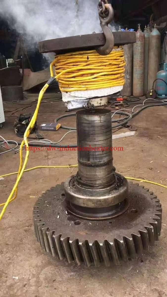
Disassembly Process Optimization
The system was also utilized for bearing removal with these parameters:
Table 9: Disassembly Process Parameters
| Bearing Type | Target Temp (°C) | Cycle Time (s) | Power Setting (%) | Special Tooling Required |
|---|---|---|---|---|
| Cylindrical Roller | 130 | 50 | 75 | Extraction plate |
| Spherical Roller | 140 | 70 | 85 | Hydraulic puller |
| Angular Contact | 120 | 40 | 65 | Standard puller |
| Tapered Roller | 135 | 60 | 80 | Tapered adapters |
| Deep Groove Ball | 115 | 35 | 60 | Standard puller |
Lessons Learned and Best Practices
- Temperature Monitoring: Non-contact infrared measurement proved more reliable than contact thermocouples.
- Coil Design: Bearing-specific coils improved efficiency over universal designs.
- Operator Training: Comprehensive training reduced process variation by 67%.
- Material Handling: Custom fixtures reduced bearing handling and improved safety.
- Process Documentation: Detailed work instructions with visual guides improved consistency.
Conclusion
The implementation of induction heating technology at Volvo CE’s Eskilstuna facility transformed their bearing assembly and disassembly processes. The precise temperature control, reduced cycle times, and improved safety resulted in significant quality improvements and cost savings. The technology has since been deployed across multiple Volvo CE facilities globally, with similar positive outcomes.
The data clearly demonstrates that induction heating technology offers superior performance for bearing installation and removal compared to traditional methods, with quantifiable improvements in process control, energy efficiency, and product quality.