Three-Joint Copper Tee Induction Brazing
Simultaneous Induction Brazing of T-Shaped Copper Assemblies with the HLQ DWS-20
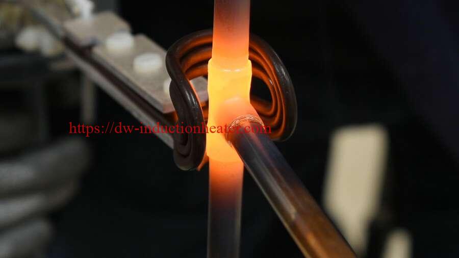
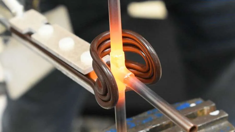
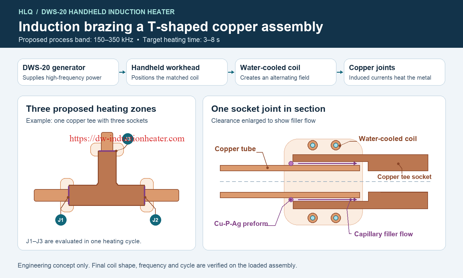
The HLQ DWS-20 Handheld Induction Heater can be configured to evaluate simultaneous brazing of three joints on a T-shaped copper assembly. The proposed setup uses a 150–350 kHz process frequency band, a target heating time of 3–8 seconds per powered cycle, and a custom coil matched to the joint layout. A separate single-joint trial establishes the baseline for filler flow and heat distribution.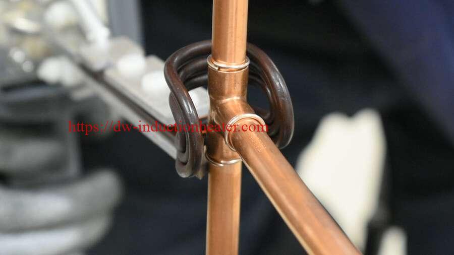
Application: Copper-to-copper induction brazing of tee assemblies and straight tube connections.
Industry: HVAC and refrigeration manufacturing.
Application Objectives
The three-joint trial evaluates whether one heating cycle can bring all joint locations into the filler alloy’s working temperature range. Each joint must reach that range before the first joint to heat shows signs of overheating. The single-joint trial provides a baseline using the actual tube, fitting and filler.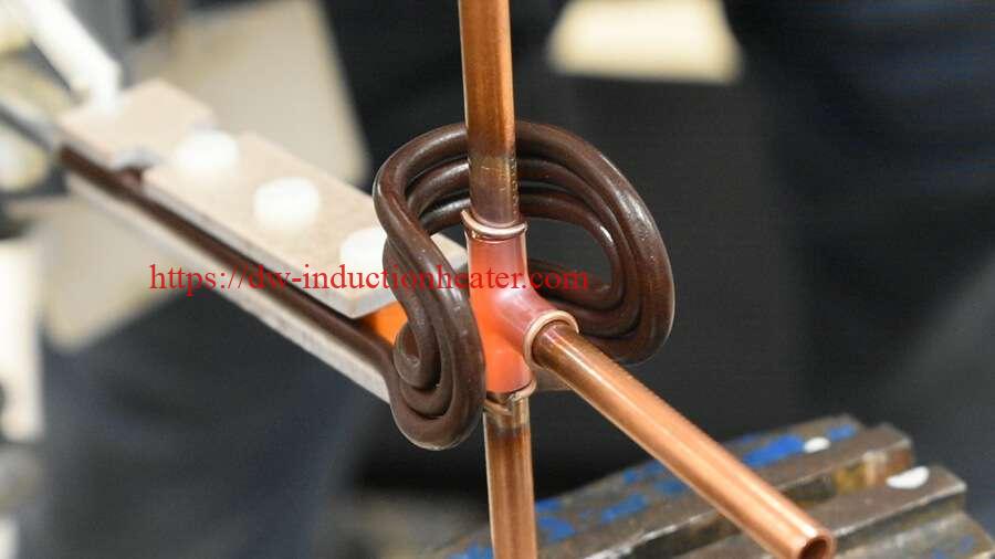
Equipment
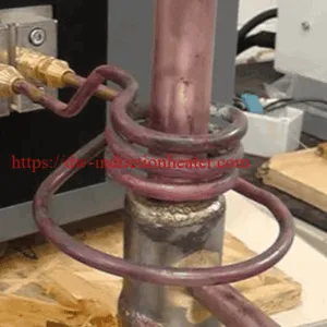
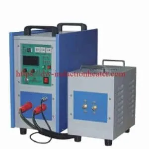
The proposed workstation uses the HLQ DWS-20 with a remote heating head, a custom water-cooled copper coil and a locating fixture. The handheld induction brazing heater brings the coil to the fixture. Locating stops control the assembly position and coil clearance from one cycle to the next.
Materials
- Base material: Copper tubing and copper fittings.
- Reference tube sizes: 6, 8, 10 and 12 mm outside diameter with a nominal 1 mm wall thickness.
- Brazing filler: Preformed copper-phosphorus-silver (Cu-P-Ag) rings. Select ring dimensions and filler quantity for the actual socket clearance.
- Joint preparation: Clean the mating surfaces and follow the selected filler supplier’s guidance on flux for the specific material combination.
Key Process Parameters
| Parameter | Application setting |
|---|---|
| Equipment | HLQ DWS-20 Handheld Induction Heater |
| Proposed process frequency | 150–350 kHz, subject to confirmation with the selected workhead and loaded coil |
| Target heating time | 3–8 seconds of induction power-on time per trial cycle |
| Trial configurations | Single copper tube joint and three joints heated in one cycle |
| Filler form | Cu-P-Ag preformed rings |
Working Principle
High-frequency current in the coil creates an alternating magnetic field. Induced currents heat the copper around the sockets. When the mating surfaces reach the filler alloy’s working temperature, the rings melt and capillary action draws filler into each joint clearance.
Brazing Process
- Prepare the samples. Clean the copper surfaces, check the fit, and place a correctly sized filler ring at each specified joint. Load the assembly into the fixture and verify insertion depth.
- Establish a single-joint baseline. Record the operating frequency, power setting, heating time and filler flow using a representative tube-to-fitting joint.
- Balance the three heating zones. Evaluate custom induction brazing coils on the assembled tee. If one socket heats late, adjust the coil geometry or clearance to improve local heat distribution before extending the cycle.
- Hold and inspect. Keep the assembly in the fixture until the filler solidifies. Check all three joints for wetting, section representative samples to assess filler penetration, and perform the specified leak test where required.

Results and Production Validation
Evaluate the 3–8 second target using the production joint geometry, workhead, coil and fixture. Qualify the simultaneous process when all three joints meet the agreed inspection criteria over repeated cycles. Record the full station cycle separately so production estimates include loading, positioning, cooling and unloading.
When configuring HVAC induction brazing equipment for a copper tee, use the production drawing, tube dimensions, filler grade, available coil access and joint acceptance criteria to define the sample trial.