
Induction Heating Applications in Oil, Gas, Petrochemical and Pipeline Industries
Quick Answer
Induction heating in the oil, gas, petrochemical and pipeline industries is the use of electromagnetic induction to generate heat inside conductive metal — pipe walls, weld joints, vessel shells, valves and fittings — without an open flame, without contact with the workpiece, and without circulating hot oil through a jacket.
Across these four industries the technology is used for ten core duties: pipeline weld preheating, pipeline post weld heat treatment (PWHT), heavy oil viscosity reduction, wax and hydrate prevention, reactor vessel and process tank heating, thermal oil process heating, pipeline coating removal, flange and valve heating, offshore and field maintenance heating, and heat exchanger tube and component heating.
Key published figures: 1–400 kHz operating frequency, 5–1000 kW power output, 5–50 mm coupling distance, ±5–10 °C control accuracy, 380–690 V input and 20–200 L/min cooling requirement. Published heating rate for induction is 40–100 °C/min against 10–30 °C/min for resistance and 15–40 °C/min for gas torches, with energy efficiency of 80–90 % against 60–70 % and 30–40 % respectively.
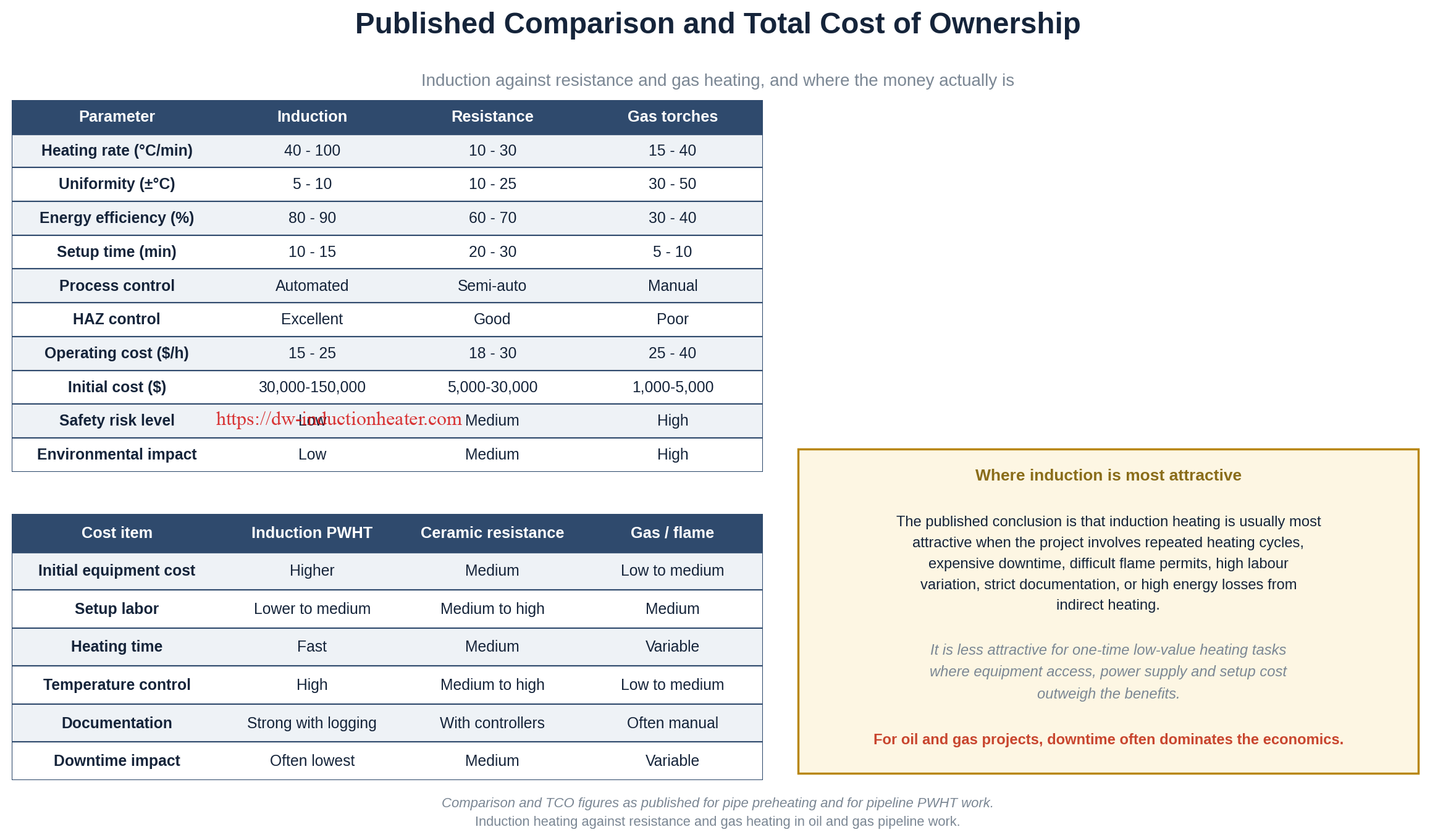
Induction heating is not automatically the correct answer. It is most attractive where a project involves repeated heating cycles, expensive downtime, difficult flame permits, high labour variation, strict documentation requirements, or high energy losses from indirect heating. It is less attractive for one-time, low-value heating tasks where equipment access, power supply and setup cost outweigh the benefit.
Table of Contents
- What is Induction Heating in Oil, Gas, Petrochemical and Pipeline Industries?
- Working Principle
- Key Applications
- Suitable Materials and Industries
- Technical Specifications
- Recommended Model Selection
- Process Workflow
- Common Problems and Solutions
- Engineering Selection Guide
- Advantages and Limitations
- Real Engineering Case Study
- Why Choose HLQ?
- 6 Core FAQs
What is Induction Heating in Oil, Gas, Petrochemical and Pipeline Industries?
Induction heating is an electromagnetic process in which alternating current in an inductor produces a changing magnetic field. That field penetrates a nearby conductive workpiece and induces eddy currents inside the metal. The metal’s own electrical resistance converts those currents into heat, in the metal itself, rather than in a burner, a resistive element, or a circulating hot-oil circuit.
For oil and gas operators, EPC contractors and refinery maintenance teams, this matters because the workpieces are pressure boundaries. A pipeline, a reactor vessel and a heat exchanger tube are all pressure-containing equipment, and local heating around them carries metallurgical, coating and code consequences. Induction heating was examined in detail in our guide to guaranteed induction heating in the oil and gas industry, which sets out the ten applications, the industry constraints and the total cost of ownership framework that this page expands across the petrochemical sector as well.
Across the combined oil, gas, petrochemical and pipeline industries, three characteristics define where induction belongs:
- No direct flame, but still hot work. Induction removes the burner and the open flame from the work area, but it still creates hot surfaces, it still needs a hot work permit on most sites, and it introduces an electrical load into a zone that may be classified as hazardous.
- Heat is generated in the metal. Because the workpiece is the heat source, energy is delivered across the wall rather than through it. For a coated or insulated pipe this is decisive: the coating does not have to survive direct burner impingement, and the field passes through non-conductive insulation to heat the steel underneath.
- Geometry decides the result, not just power. The gap between coil and metal, the number of turns, the frequency and the insulation determine the heating rate, the depth of heat and the uniformity. Rated kilowatts alone determine nothing.
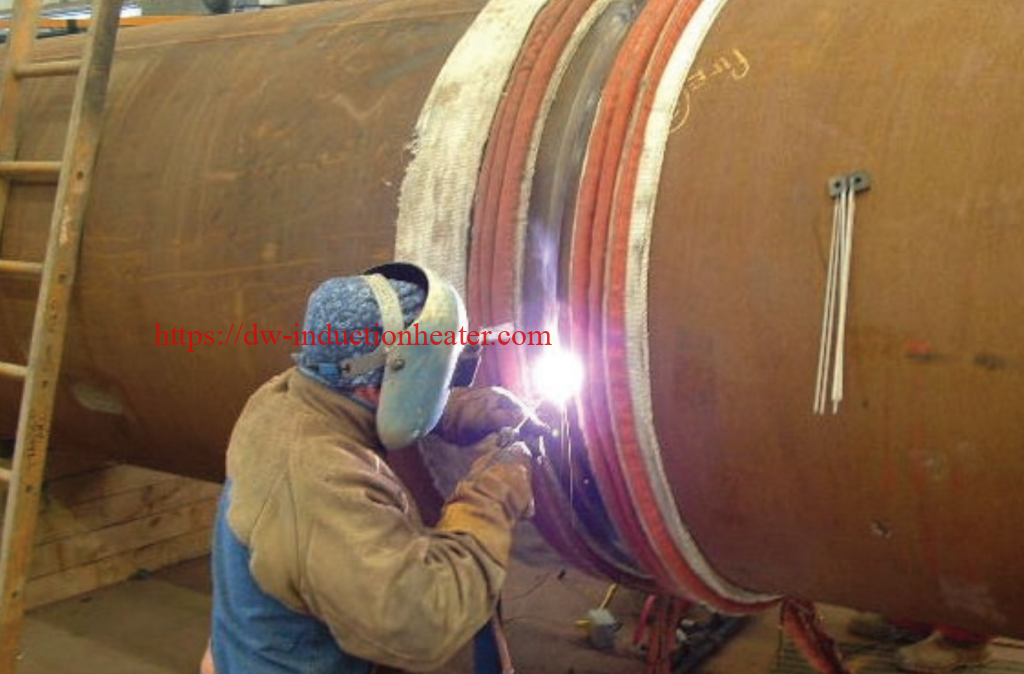
Induction heating is therefore not a general-purpose replacement for fired heaters. It is an engineering choice for a specific set of duties in these four sectors, and the sections below cover the physics, the applications, the materials, the published specification ranges, the selection logic, the cost, and the case data.
Working Principle
The chain of events in any induction heating duty is the same, whether the workpiece is a pipe weld, a reactor shell or a valve body.
- AC power is converted. An IGBT or transistor power supply converts three-phase industrial electricity into an alternating current at a controlled frequency. The oscillation band determines how deep the heat goes.
- A magnetic field is created. Current flowing through the induction coil — a rigid copper coil, a split coil, a scanning coil or a flexible induction heating cable wound on the workpiece — produces a changing magnetic field around the conductor.
- Eddy currents are induced in the workpiece. Where the field crosses into conductive metal it induces circulating currents. Below the Curie point of a ferromagnetic material these currents add to the hysteresis loss; above it, only eddy current contributes.
- Heat is generated in the metal. The induced currents meet the electrical resistance of the steel and become heat, distributed from the outer surface inward to the penetration depth set by frequency.
- The heat is trapped and controlled. Insulation around the heated zone limits losses, thermocouples report real wall temperature, and a PLC or PID controller modulates power to follow the programmed ramp, soak and cooling profile.
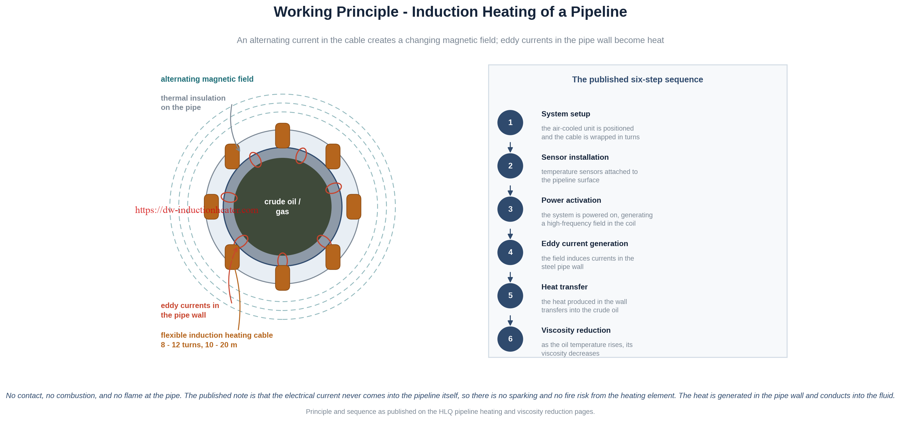
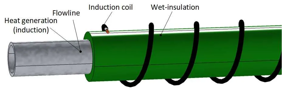
The published principle graphic on our pipeline viscosity article shows the same mechanism applied to an oil line, with heat generated in the steel pipe wall and transferred into the crude oil it contains.

Two practical consequences follow directly from the physics and are used repeatedly in selection:
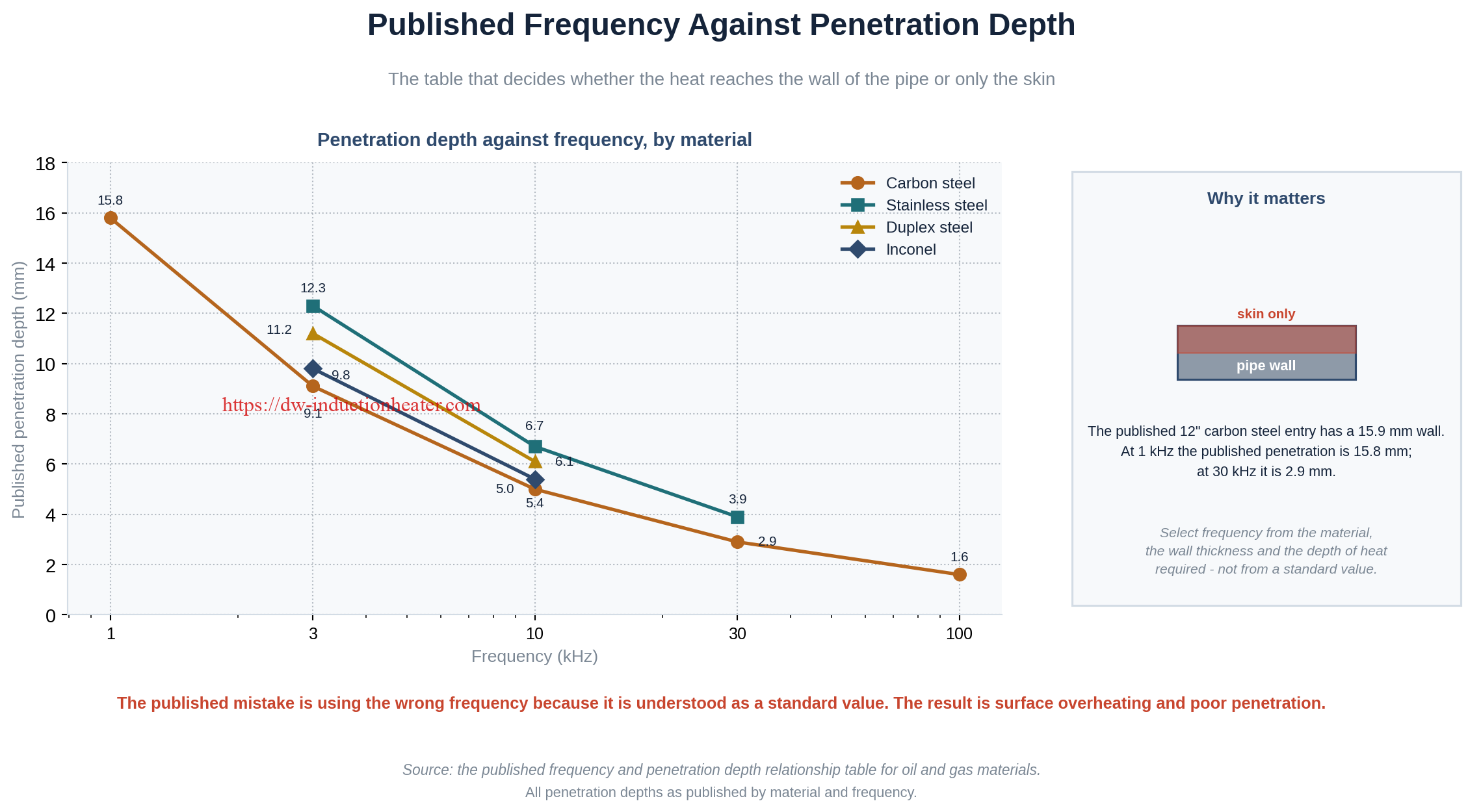
- Frequency sets penetration depth. Published penetration for carbon steel is 15.8 mm at 1 kHz, 9.1 mm at 3 kHz, 5.0 mm at 10 kHz, 2.9 mm at 30 kHz and 1.6 mm at 100 kHz. A pipe with a 25.4 mm wall heated at 30 kHz heats its skin far more than its wall.
- Coupling distance sets efficiency. The magnetic field is strongest next to the coil and falls with distance, so the gap between coil and metal is the cheapest parameter to get right and the most expensive one to get wrong.
Key Applications
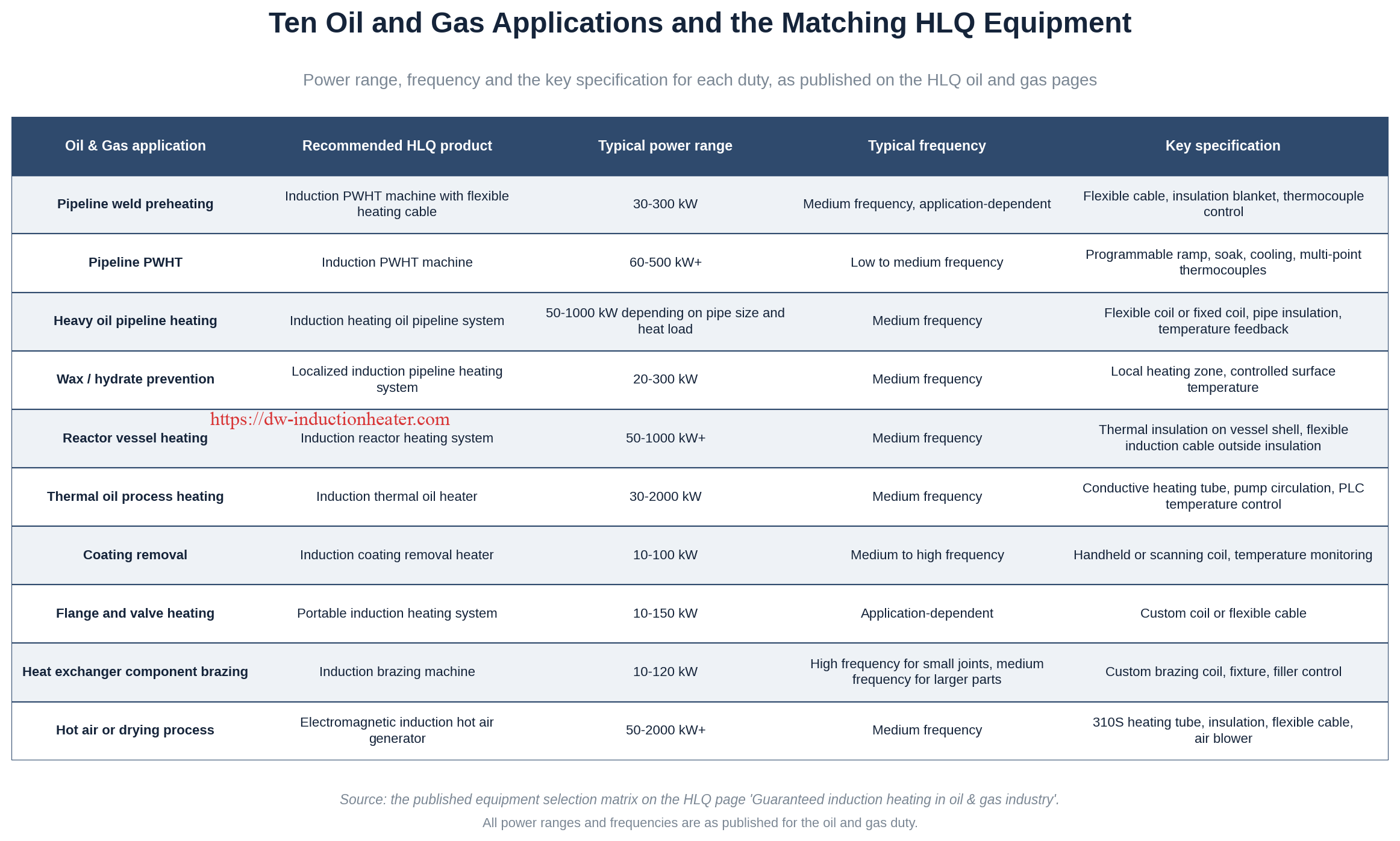
Ten applications are published for induction heating across the oil and gas, petrochemical and pipeline sectors, together with the matching HLQ equipment, power range and frequency for each.
1. Pipeline weld preheating
Preheating the parent metal before the weld is made controls welding cooling conditions and reduces specific cracking risks in hydrogen-sensitive steels. Induction heating gives fast circumferential heating around the weld zone with low setup time, which is where it wins against resistance blankets on large-diameter pipe. The temperature is set by the WPS, not by the equipment.
2. Pipeline post weld heat treatment (PWHT)
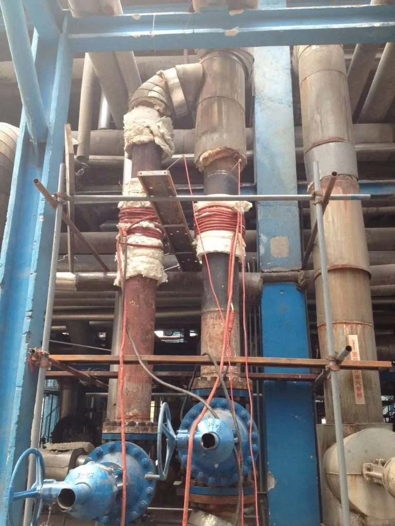
PWHT follows welding and delivers a prescribed soak and cooling cycle to achieve a specified metallurgical and stress-relief condition. It is more demanding than preheating: it needs a documented complete thermal cycle, a controlled ramp, a soak at the procedure temperature and controlled cooling. Induction PWHT equipment wraps a flexible induction heating cable around the weld band with high-temperature insulation blankets, multi-point thermocouples and a programmable controller. For the specific case of a large-diameter carbon steel line, see our article on post weld heat treatment of large diameter carbon steel pipeline using induction heating.
3. Heavy oil viscosity reduction
When heavy crude drops in temperature its viscosity rises sharply and the line can block. Induction heating the steel pipe wall transfers heat into the fluid and restores flow. The published reference case uses a carbon steel pipe of 219 mm outer diameter and 8–12 mm wall carrying heavy crude oil at 40–80 °C, heated by an air-cooled 30–60 kW unit at 10–40 kHz. Detail is on induction heating oil pipelines for reducing viscosity and ensuring flowability.
4. Wax and hydrate prevention
Flow assurance depends on keeping the line above the wax appearance temperature (WAT) and the hydrate formation temperature. Induction heating holds the pipe wall inside that band by precise control and continuous monitoring, rather than by overheating the whole line. It is used on subsea lines where cold seawater drives the formation rate up, and in arctic and cold-climate service. See wax and hydrate prevention in oil and gas pipelines with induction heating.
5. Reactor vessel and process tank heating
Reactor shells, kettles, autoclaves, distillation vessels and process tanks are heated from the outside. The vessel itself becomes the heating body: thermal insulation is wrapped on the shell and the induction coil or flexible cable sits immediately outside the insulation, so the field passes through it and heats the steel. The published duties are resin production, polymerisation, petrochemical processing, distillation and solvent recovery, catalytic reaction, high-viscosity material heating and chemical synthesis. The full engineering treatment is on induction heating for chemical and petrochemical reactors.

6. Thermal oil process heating
A conductive heating tube inside the thermal oil circuit is heated by induction, and the heated oil is circulated by a pump with PLC temperature control. This gives a fuel-free electric process heat source, which matters where flame is restricted or where the site is moving toward electrification. Published power range for this duty is 30–2000 kW.
7. Pipeline coating removal
Induction heating weakens the bond between an aged anti-corrosion coating and the steel beneath it, so the coating can then be stripped mechanically with scrapers instead of being burned off with a flame. It replaces grinding dust and uncontrolled smoke with controlled heat, and it requires fume extraction plus a review of the coating’s maximum allowable temperature.

8. Flange, valve and fitting heating
Flanges, valves, hubs and sleeves are heated for assembly, disassembly and shrink-fit expansion. A portable induction system with a custom coil or a flexible cable covers this duty at 10–150 kW, and the same equipment serves pipe joints, bends and nozzles.
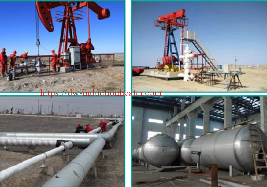
9. Offshore and field maintenance heating
Portable and air-cooled units are deployed to offshore platforms, remote fields and desert sites where there is no fixed plant, limited electrical infrastructure and no cooling water. This duty is where the absence of external cooling water matters most.
10. Heat exchanger tube and component heating
Tube bundles and heat exchanger components are heated locally without affecting the rest of the assembly. Brazing heat exchangers is the published application in this group, at 10–120 kW, with a custom brazing coil, a fixture and filler control.
Suitable Materials and Industries
The requirement is simple and absolute: the metal must be electrically conductive. Induction heating does not directly heat glass, PTFE, ceramic or plastic — those need either a conductive outer shell or a susceptor structure. Published suitability for the petrochemical process vessels in this industry set is given below.
| Material | Induction Heating Suitability | Typical Use | Engineering Notes |
|---|---|---|---|
| Carbon steel | Excellent | Petrochemical vessels, oil tanks, process reactors | Strong magnetic response, high heating efficiency |
| Stainless steel 304 | Good | Chemical reactors, sanitary process vessels | Requires suitable frequency and close coil design |
| Stainless steel 316L | Good | Corrosive chemical reactors, pharmaceutical vessels | Common for corrosion resistance; induction design must be optimized |
| Low-alloy steel | Excellent | Pressure vessels, petrochemical reactors | Good heating performance and structural strength |
| Nickel alloy | Application-dependent | High-corrosion or high-temperature chemical reactors | Requires testing because electrical and magnetic properties vary |
| Glass-lined steel | Possible with caution | Corrosive chemical reactors | Heat is generated in steel shell; glass lining temperature limits must be respected |
| PTFE, plastic, ceramic, glass | Not directly suitable | Special corrosion-resistant systems | Requires conductive outer shell or susceptor heating structure |
For pipeline work specifically, the common materials are carbon steel, low-alloy steel, stainless steel, duplex stainless and nickel alloys, plus coated pipe. Material affects heating rate, frequency selection, magnetic response and temperature limits, so the grade must be confirmed before power is sized. The published approach to pre-heating pipes and tubes in the oil and gas industry with induction heating systems sets out the same material logic for the pipe and tube duties, together with the published heating performance data reproduced in the Technical Specifications section below.

Across these four industries the served sectors are upstream oil and gas production, transmission pipeline construction and repair, refinery and petrochemical processing, offshore and marine installation, chemical manufacturing, and plant maintenance and inspection. HLQ’s own scope, as published on the company page, covers oil and gas, pressure vessels, pipelines, boilers and shipbuilding for PWHT systems, and chemical, petrochemical, recycling and energy applications for custom systems.
Technical Specifications
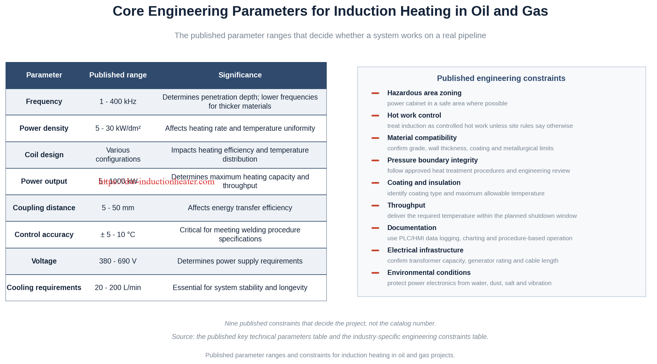
These are the published parameter ranges that decide whether a system works on a real pipeline or vessel, and their significance.
| Parameter | Published Range | Significance |
|---|---|---|
| Frequency | 1 – 400 kHz | Determines penetration depth; lower frequencies for thicker materials |
| Power density | 5 – 30 kW/dm² | Affects heating rate and temperature uniformity |
| Coil design | Various configurations | Impacts heating efficiency and temperature distribution |
| Power output | 5 – 1000 kW | Determines maximum heating capacity and throughput |
| Coupling distance | 5 – 50 mm | Affects energy transfer efficiency |
| Control accuracy | ± 5 – 10 °C | Critical for meeting welding procedure specifications |
| Voltage | 380 – 690 V | Determines power supply requirements |
| Cooling requirements | 20 – 200 L/min | Essential for system stability and longevity |
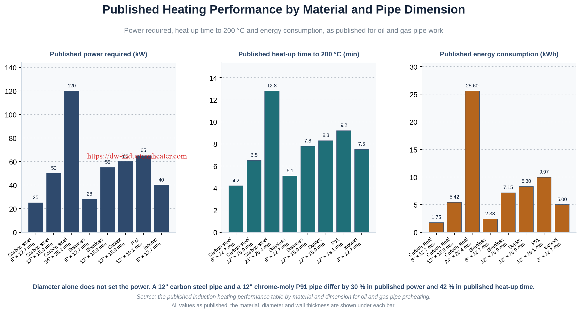
Published heating performance by material and pipe dimension, showing the power required, the heat-up time to 200 °C and the energy consumed for each combination:
| Material | Pipe Diameter (in) | Wall Thickness (mm) | Power Required (kW) | Heat-up Time to 200 °C (min) | Energy Consumption (kWh) |
|---|---|---|---|---|---|
| Carbon steel | 6 | 12.7 | 25 | 4.2 | 1.75 |
| Carbon steel | 12 | 15.9 | 50 | 6.5 | 5.42 |
| Carbon steel | 24 | 25.4 | 120 | 12.8 | 25.6 |
| Stainless steel | 6 | 12.7 | 28 | 5.1 | 2.38 |
| Stainless steel | 12 | 15.9 | 55 | 7.8 | 7.15 |
| Duplex steel | 12 | 15.9 | 60 | 8.3 | 8.30 |
| Chrome-Moly (P91) | 12 | 19.1 | 65 | 9.2 | 9.97 |
| Inconel | 8 | 12.7 | 40 | 7.5 | 5.00 |
Two readings from this table matter in practice. A 12-inch carbon steel pipe with a 15.9 mm wall needs 50 kW, while a 12-inch P91 pipe with a 19.1 mm wall needs 65 kW — the same nominal diameter and roughly 30 % more published power, purely because of wall thickness and alloy content. And between a 6-inch and a 24-inch carbon steel line, published power rises from 25 kW to 120 kW while energy per joint rises from 1.75 kWh to 25.6 kWh.

Published penetration depth by material and frequency — the table that decides whether the heat reaches the pipe wall or only the skin:
| Material | Frequency (kHz) | Penetration Depth (mm) |
|---|---|---|
| Carbon steel | 1 | 15.8 |
| Carbon steel | 3 | 9.1 |
| Carbon steel | 10 | 5.0 |
| Carbon steel | 30 | 2.9 |
| Carbon steel | 100 | 1.6 |
| Stainless steel | 3 | 12.3 |
| Stainless steel | 10 | 6.7 |
| Stainless steel | 30 | 3.9 |
| Duplex steel | 3 | 11.2 |
| Duplex steel | 10 | 6.1 |
| Inconel | 3 | 9.8 |
| Inconel | 10 | 5.4 |
Published power ranges and frequencies by application, with the key specification that governs each duty:
| Oil & Gas Application | Recommended HLQ Product | Typical Power Range | Typical Frequency | Key Specification |
|---|---|---|---|---|
| Pipeline weld preheating | Induction PWHT Machine with flexible heating cable | 30–300 kW | Medium frequency, application-dependent | Flexible cable, insulation blanket, thermocouple control |
| Pipeline PWHT | Induction PWHT Machine | 60–500 kW+ | Low to medium frequency | Programmable ramp, soak, cooling, multi-point thermocouples |
| Heavy oil pipeline heating | Induction Heating Oil Pipeline System | 50–1000 kW depending on pipe size and heat load | Medium frequency | Flexible coil or fixed coil, pipe insulation, temperature feedback |
| Wax/hydrate prevention | Localized Induction Pipeline Heating System | 20–300 kW | Medium frequency | Local heating zone, controlled surface temperature |
| Reactor vessel heating | Induction Reactor Heating System | 50–1000 kW+ | Medium frequency | Thermal insulation on vessel shell, flexible induction cable outside insulation |
| Thermal oil process heating | Induction Thermal Oil Heater | 30–2000 kW | Medium frequency | Conductive heating tube, pump circulation, PLC temperature control |
| Coating removal | Induction Coating Removal Heater | 10–100 kW | Medium to high frequency | Handheld or scanning coil, temperature monitoring |
| Flange and valve heating | Portable Induction Heating System | 10–150 kW | Application-dependent | Custom coil or flexible cable |
| Heat exchanger component brazing | Induction Brazing Machine | 10–120 kW | High frequency for small joints, medium frequency for larger parts | Custom brazing coil, fixture, filler control |
| Hot air or drying process | Electromagnetic Induction Hot Air Generator | 50–2000 kW+ | Medium frequency | 310S heating tube, insulation, flexible cable, air blower |
For petrochemical reactor duties, the published specification envelope is: power rating 10 kW – 1000 kW+, frequency 1 kHz – 100 kHz, three-phase input at 380 V / 415 V / 480 V or custom, reactor capacity 50 L – 50,000 L+, operating temperature ambient to 600 °C+, insulation of ceramic fibre, rock wool or high-temperature blanket, coil type of copper tube coil, flexible induction cable or split coil, cooling by water or air, and PID, PLC, HMI control with thermocouple feedback.
Recommended Model Selection
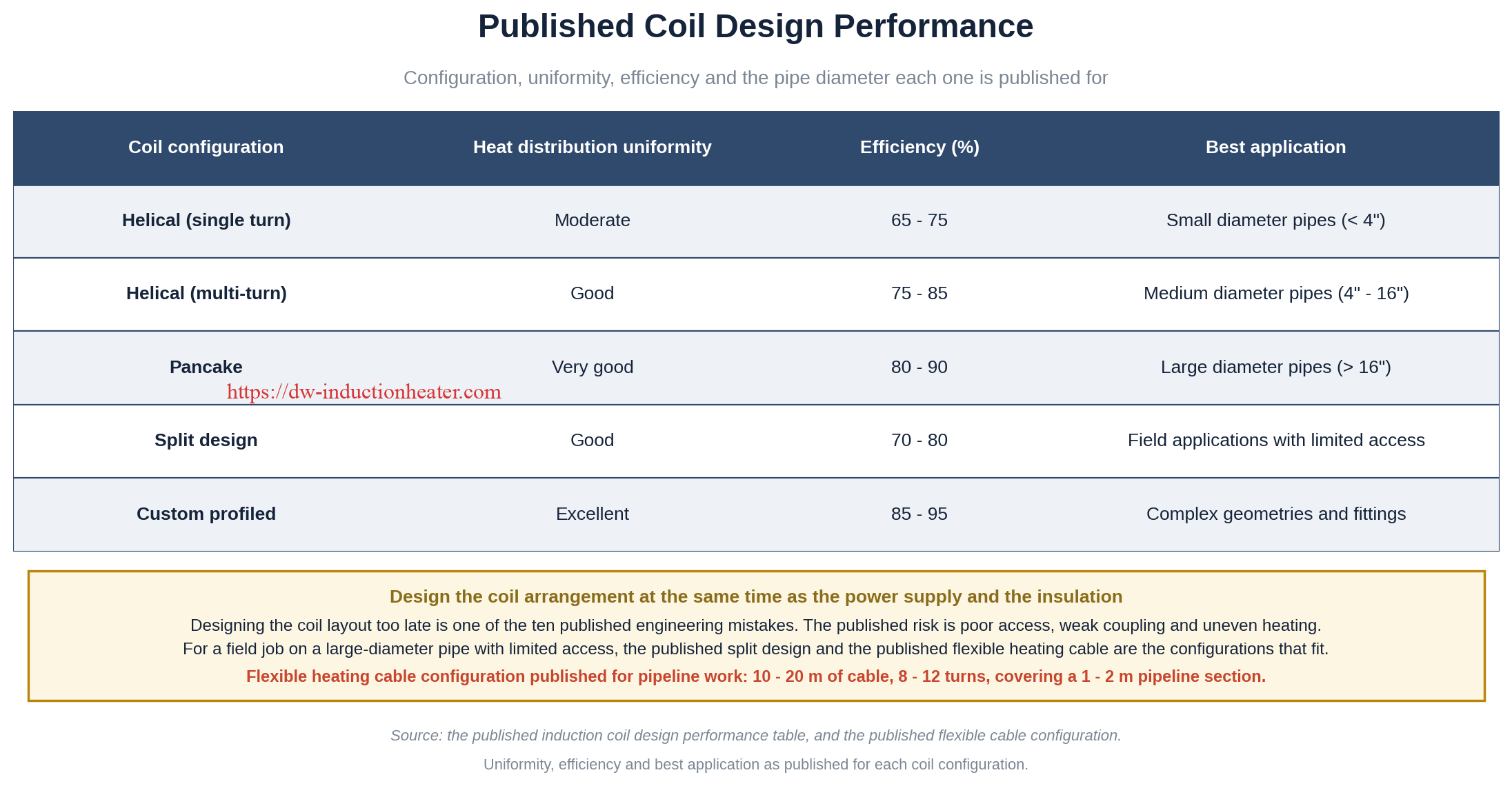
Model selection follows the duty, and the duty follows the heat load — not the pipe diameter alone. The published coil design performance table below determines which inductor arrangement is correct for each geometry before any power figure is chosen.
| Coil Configuration | Heat Distribution Uniformity | Efficiency (%) | Best Application |
|---|---|---|---|
| Helical (Single Turn) | Moderate | 65–75 | Small diameter pipes (<4″) |
| Helical (Multi-Turn) | Good | 75–85 | Medium diameter pipes (4″–16″) |
| Pancake | Very Good | 80–90 | Large diameter pipes (>16″) |
| Split Design | Good | 70–80 | Field applications with limited access |
| Custom Profiled | Excellent | 85–95 | Complex geometries and fittings |
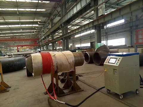
The published flexible heating cable configuration for pipeline work is 10–20 m of cable, 8–12 turns, covering a 1–2 m pipeline section. It is usable on pipeline joints, valves, flanges and bends, which makes it the practical choice for field work where a rigid inductor cannot be fabricated to the geometry.
Selection by duty and scale:
| Duty | Published Power Class | Recommended Inductor | Control and Documentation Requirement |
|---|---|---|---|
| Flange, valve and fitting heating | 10–150 kW | Custom coil or flexible cable | Digital temperature control; record if the procedure requires |
| Coating removal | 10–100 kW | Handheld or scanning coil | Surface temperature monitoring plus fume extraction |
| Pipeline weld preheating | 30–300 kW | Flexible heating cable with insulation blanket | Thermocouple control to the WPS |
| Pipeline PWHT | 60–500 kW+ | Flexible cable or dedicated PWHT coil | Programmable ramp, soak and cooling with chart recording |
| Reactor vessel heating | 50–1000 kW+ | Flexible cable outside insulation, or sectional coil | PLC + HMI with PID and multi-point feedback |
| Thermal oil process heating | 30–2000 kW | Conductive heating tube with pump circulation | PLC temperature control on oil outlet |
For reactor vessels specifically, the published capacity-to-power mapping is: 50–300 L on 10–40 kW with a compact copper coil or flexible cable; 300–1000 L on 40–120 kW with flexible cable or sectional coil; 1000–3000 L on 100–300 kW with multi-zone coil; 3000–10,000 L on 250–800 kW with a multi-zone water-cooled induction coil; and above 10,000 L on custom 500–1000 kW+ with segmented induction heating zones.
Process Workflow
Ten steps separate an objective from a standardised, documented procedure. This is the published implementation roadmap for an oil and gas induction heating project, and it applies unchanged to petrochemical reactor duties.
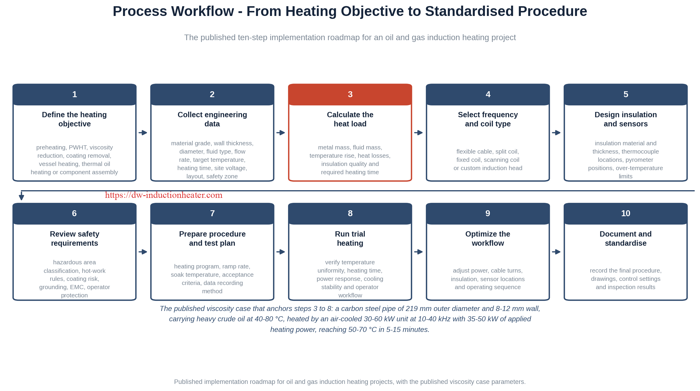
- Define the heating objective. Identify whether the project is preheating, PWHT, viscosity reduction, coating removal, vessel heating, thermal oil heating or component assembly. Each objective has a different temperature band, a different holding requirement and a different documentation burden.
- Collect engineering data. Material grade, wall thickness, diameter, fluid type, flow rate, target temperature, heating time, site voltage, layout and safety zone information.
- Calculate heat load. Metal mass, fluid mass, temperature rise, heat losses, insulation quality and required heating time.
- Select frequency and coil type. Flexible cable, split coil, fixed coil, scanning coil or custom induction head, according to geometry and required depth of heat.
- Design insulation and sensors. Insulation material and thickness, thermocouple locations, pyrometer positions and over-temperature limits.
- Review safety requirements. Hazardous area classification, hot work rules, coating risk, grounding, EMC and operator protection.
- Prepare procedure and test plan. Heating program, ramp rate, soak temperature, acceptance criteria and data recording method.
- Run trial heating. Verify temperature uniformity, heating time, power response, cooling system stability and operator workflow.
- Optimize the workflow. Adjust power, cable turns, insulation, sensor locations and operating sequence.
- Document and standardise. Record the final procedure, drawings, control settings, inspection results and maintenance requirements.
For a localised pipeline heating duty the field procedure runs in six physical steps: system setup, sensor installation, power activation, eddy current generation, heat transfer into the fluid, and viscosity reduction.
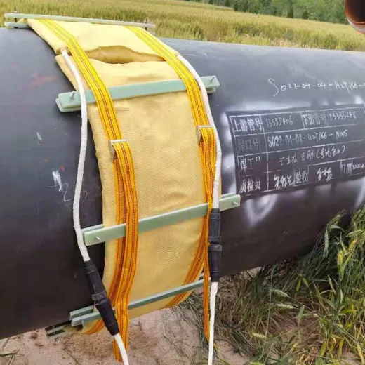
The published field arrangement places the power cabinet, the flexible induction cable, the insulation and the temperature sensors in defined zones, and the published safety practice is that the power cabinet goes in a safe area where possible.

Common Problems and Solutions
The following ten engineering mistakes are published for oil and gas induction heating projects. Each is stated with why it happens, the risk it creates and how to avoid it.
| Engineering Mistake | Why It Happens | Project Risk | How to Avoid It |
|---|---|---|---|
| Selecting power only by pipe diameter | Diameter is visible, but heat load also depends on wall thickness, material, temperature rise, insulation and time | Underpowered system or excessive heating time | Calculate total heat load using pipe mass, fluid mass, target temperature, heating time and losses |
| Ignoring insulation quality | Engineers focus on power supply but underestimate heat loss | Energy waste, slow heating, unstable temperature | Use suitable insulation thickness and install it correctly around the heating zone |
| Using the wrong frequency | Frequency selection is misunderstood as a standard value | Surface overheating, poor penetration, low efficiency | Select frequency based on material, wall thickness, heating depth and coil geometry |
| Placing sensors in unrepresentative locations | Thermocouples are installed where convenient, not where temperature matters | False temperature readings and poor control | Use multi-point thermocouples and define control points according to the heat treatment procedure |
| Assuming induction is always safe because there is no flame | Induction is often marketed as flameless | Hot surface ignition risk, damaged coatings, unsafe operation in hazardous zones | Perform site safety review, hazardous area assessment and hot-work permitting |
| Ignoring coating temperature limits | The metal is the heating target, but coatings are close to the heat source | Coating damage, smoke, toxic fumes or failed corrosion protection | Identify coating type and allowable temperature before applying induction heat |
| Not checking electrical infrastructure | Mechanical engineers may specify heating demand without checking power supply | Voltage instability, generator overload, nuisance trips | Confirm voltage, phase, transformer capacity, grounding, generator rating and cable length |
| Designing coil layout too late | Equipment selection focuses on power supply first | Poor access, weak coupling, uneven heating | Design coil or flexible cable arrangement at the same time as power and insulation selection |
| Underestimating cooling requirements | Cooling is treated as auxiliary equipment | Coil overheating, cable damage, production stoppage | Size cooling system for continuous duty, water quality, ambient temperature and pressure drop |
| Not documenting heating cycles | Manual heating is treated as a craft operation | Compliance gaps and quality disputes | Use data logging, temperature charts and procedure-based records |
Typical process faults and their published engineering solutions:
| Problem | Possible Cause | Engineering Solution |
|---|---|---|
| Slow heating speed | Power is too low, insulation is poor, workpiece mass is high, or material heat load is underestimated | Recalculate heat load, increase power, improve insulation, or use multi-zone heating |
| Uneven temperature | Poor coil distribution, no agitation, incorrect sensor position, or uneven insulation | Optimize coil layout, add agitation, use multi-point sensors and improve insulation wrapping |
| Coil overheating | Insufficient cooling, wrong cable size, poor connection, or excessive current | Check cooling flow, use correct cable rating, tighten connections and verify power matching |
| Temperature overshoot | PID settings too aggressive, sensor lag, or high thermal inertia | Adjust PID parameters, reduce ramp rate and install the sensor closer to the representative heating zone |
| Low heating efficiency | Large air gap, poor magnetic coupling, incorrect frequency, or insufficient insulation | Reduce coil-to-workpiece distance, select proper frequency and increase insulation quality |
| Power supply alarm | Overcurrent, overvoltage, cooling failure, phase loss, or load mismatch | Check input power, cooling system, coil connection, matching capacitor and grounding |
| Local hot spots | Uneven coil pitch, metallic support interference, poor process mixing, or damaged insulation | Use uniform coil spacing, avoid magnetic metal supports near the coil, improve agitation and repair insulation |
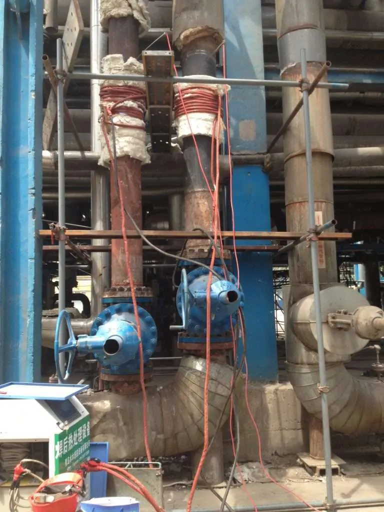
| Electromagnetic interference | Poor grounding, unshielded control lines, or improper cabinet layout | Use proper grounding, shielding, cable separation and an EMC-compliant control cabinet design |
Engineering Selection Guide
This is the selection checklist applied to a pipeline or reactor project before a quotation is written. Each factor is answered from the site survey data, not from the equipment catalogue.
| Selection Factor | What to Check | Recommended Engineering Decision |
|---|---|---|
| Workpiece material | Carbon steel, stainless steel, alloy steel, glass-lined steel | Confirm electrical conductivity and temperature limit before design |
| Wall thickness | Thin wall, medium wall, thick pressure vessel | Use lower frequency for thicker walls and deeper heating |
| Target temperature | Process temperature and workpiece surface temperature | Select insulation, sensor and coil rating according to maximum temperature |
| Heating time | Required time from ambient to target temperature | Calculate heat load and choose power with safety margin |
| Process material | Oil, resin, solvent, polymer, slurry, acid, alkali | Consider viscosity, boiling point, corrosion and agitation |
| Agitation | With agitator or without agitator | Agitation is recommended for uniform internal temperature |
| Installation space | Available clearance around the workpiece | Use flexible induction cable or split coil for limited retrofit space |
| Safety area | Normal industrial area or hazardous area | Use suitable explosion-proof control, grounding and isolation design where required |
| Operation mode | Batch, semi-continuous, continuous | Configure PLC logic according to the process cycle |
| Cooling requirement | Coil, cable, capacitor and power supply cooling | Choose water cooling for high power and continuous operation |
| Hazardous area zoning | Classified areas with flammable gas or vapour | Place the power cabinet in a safe area where possible; use approved enclosures, permits, gas testing, grounding and site-specific safety review |
| Electrical infrastructure | Remote field power availability | Confirm transformer capacity, generator compatibility, cable length and cooling water availability |
For reference, the standards and frameworks that commonly influence these projects are listed below. The applicable standard depends on country, operator, project scope and application, and the specific edition must be confirmed for each project.
| Standard / Framework | Relevant Area | Why It Matters for Induction Heating |
|---|---|---|
| ASME Section IX | Welding and brazing procedure qualification | Relevant when induction heating is used for weld preheating, PWHT or brazing procedure support |
| ASME Section VIII | Pressure vessels | Important when heating reactor vessels, pressure vessels or process containers |
| API 1104 | Pipeline welding | Relevant for pipeline weld preheating, welding qualification and field heat treatment procedures |
| API 650 | Welded tanks for oil storage | Relevant when induction heating is used around storage tank fabrication or repair |
| API 570 | Piping inspection code | Relevant to in-service piping inspection, repair and maintenance heating |
| NACE / AMPP Standards | Corrosion control and protective coatings | Important when induction heating may affect coatings, corrosion protection or surface preparation |
| NORSOK Standards | Offshore oil and gas engineering | Relevant for offshore equipment, materials, welding and safety practices |
| IECEx / ATEX | Explosive atmosphere equipment | Relevant when equipment is used near hazardous areas or classified zones |
| ISO 9001 | Quality management | Supports supplier qualification and manufacturing quality control |
| Site-Specific Hot Work Procedures | Plant safety and maintenance | Often determines whether induction heating can be used and under what controls |

Advantages and Limitations
Published comparison of the three heating technologies used on the same pipeline duty:
| Parameter | Induction Heating | Resistance Heating | Gas Torches |
|---|---|---|---|
| Heating Rate (°C/min) | 40–100 | 10–30 | 15–40 |
| Temperature Uniformity (±°C) | 5–10 | 10–25 | 30–50 |
| Energy Efficiency (%) | 80–90 | 60–70 | 30–40 |
| Setup Time (min) | 10–15 | 20–30 | 5–10 |
| Process Control | Automated | Semi-automated | Manual |
| Heat Affected Zone Control | Excellent | Good | Poor |
| Operating Cost ($/hour) | 15–25 | 18–30 | 25–40 |
| Initial Investment ($) | 30,000–150,000 | 5,000–30,000 | 1,000–5,000 |
| Safety Risk Level | Low | Medium | High |
| Environmental Impact | Low | Medium | High |
Cost comparison across the ownership cycle, as published for pipeline PWHT work:
| Cost Item | Induction PWHT System | Ceramic Resistance Heating | Gas / Flame-Based Heating |
|---|---|---|---|
| Initial equipment cost | Higher | Medium | Low to medium |
| Setup labor | Lower to medium | Medium to high | Medium |
| Heating time | Fast | Medium | Variable |
| Temperature control | High | Medium to high | Low to medium |
| Energy efficiency | High for local metal heating | Medium | Lower for uncontrolled field heating |
| Maintenance | Medium | Medium | Low equipment cost but more safety controls |
| Safety management | Controlled hot surface, no direct flame | Hot electrical elements | Open flame risk |
| Documentation | Strong with data logging | Available with controllers | Often manual |
| Downtime impact | Often lowest | Medium | Variable |
The published 10-year total cost of ownership framework, which is the correct tool for a business case:
| Formula Item | Calculation Method | Notes |
|---|---|---|
| Capital Cost | Equipment + accessories + installation | Include power supply, coil, cooling, sensors, insulation, fixtures |
| Energy Cost | Power consumption × operating hours × electricity/fuel price | Use actual duty cycle, not rated power only |
| Labor Cost | Setup labor + operating labor + supervision | Induction can reduce manual flame heating skill variation |
| Maintenance Cost | Parts + service + downtime for repair | Include coils, cables, cooling pumps, sensors |
| Downtime Cost | Lost production value × downtime hours | Often the largest economic factor in oil and gas |
| Quality / Rework Cost | Rejected work + rework labor + inspection delay | Better heating control can reduce rework |
| Safety / Permit Cost | Fire watch + risk control + compliance procedures | Induction can reduce open-flame exposure but still needs safety review |
Advantages. Fast heating rate with no contact between the heat source and the workpiece; no combustion and no combustion products at the workpiece; heat generated in the metal itself, so it works through insulation; tight temperature uniformity with automated control; no direct open flame, which eases flame-permit and fire-watch burden; strong documentation through PLC/HMI charting; and, on repeated duties, lower setup labour and much lower downtime impact.
Limitations. Higher initial capital cost than gas or resistance equipment; the result depends on correct coil and insulation design, not just rated power; the power supply, cooling system and cable set are all part of the specification; induction does not heat non-conductive materials directly; and it is not automatically safe — hot surfaces and ignition risk remain, so hazardous area assessment and hot work control still apply. It is also less attractive for one-time, low-value heating tasks where equipment access, power supply and setup cost outweigh the benefits.

Real Engineering Case Study
Case Study: Offshore pipeline pre-weld heating, 24-inch carbon steel, 320 welds
A North Sea offshore pipeline project implemented induction heating for pre-weld heating on a 24-inch carbon steel pipeline with a 25.4 mm wall thickness. The project involved 320 welds, each requiring pre-heating to 150 °C. Performance data was collected against the resistance heating method previously used on the same work.
| Metric | Induction Heating | Previous Method (Resistance) |
|---|---|---|
| Average Heat-up Time per Joint (min) | 11.5 | 28.3 |
| Temperature Variation Across Joint (°C) | ±7 | ±22 |
| Energy Consumption per Joint (kWh) | 21.8 | 42.5 |
| Labor Hours per Joint (h) | 0.5 | 1.2 |
| Equipment Downtime (%) | 2.1 | 8.7 |
| Total Project Duration (days) | 24 | 41 (estimated) |
| Total Energy Consumption (MWh) | 7.0 | 13.6 |
| Carbon Emissions (tonnes CO₂e) | 2.8 | 5.4 |
The implementation resulted in a 42 % reduction in project duration and a 48 % decrease in energy consumption compared with the traditional resistance heating method previously used. The wider case treatment, including the method of building the pipeline around the equipment, is covered on our page on post weld heat treatment of large diameter carbon steel pipeline using induction heating.
Published economics for that duty
| Parameter | Value |
|---|---|
| Initial Investment ($) | 85,000 |
| Annual Maintenance Cost ($) | 3,200 |
| Expected System Lifetime (years) | 12 |
| Energy Cost Savings ($/year) | 18,500 |
| Labor Cost Savings ($/year) | 32,000 |
| Project Timeline Reduction (%) | 35–45 |
| Quality Improvement Cost Benefit ($/year) | 12,000 |
| Payback Period (years) | 1.3–1.8 |
| 5-Year ROI (%) | 275 |
| 10-Year NPV ($) at 7% discount rate | 382,000 |
Case Study: Heavy oil transfer line, 219 mm carbon steel
A heavy oil transfer line suffered high viscosity during low-temperature operation, with increased pump load and difficult start-up after shutdown. A localized induction pipeline heating system was installed around the carbon steel pipe section near the pump inlet, thermal insulation was applied over the heated zone, and temperature sensors monitored pipe wall temperature.
| Item | Published Value |
|---|---|
| Pipe material | Carbon steel |
| Outer diameter | 219 mm |
| Wall thickness | 8–12 mm |
| Fluid type | Heavy crude oil |
| Operating temperature | 40–80 °C |
| Viscosity at 25 °C | Very high |
| Viscosity at 40 °C | Moderate |
| Viscosity at 60 °C | Low |
| Power supply | 30–60 kW, 380 V / 50–60 Hz, air cooled, 10–40 kHz, digital temperature control |
| Flexible heating cable | 10–20 m length, 8–12 turns, 1–2 m heating coverage |
| Heating power / time / target | 35–50 kW applied, 5–15 minutes, target 50–70 °C, 20–30 kHz |
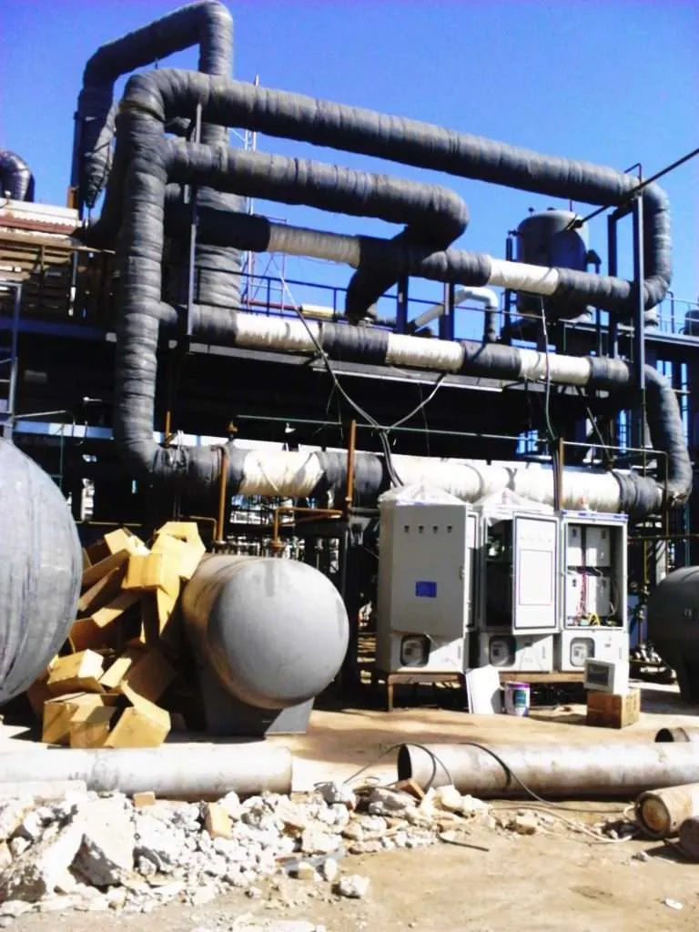
Measured outcomes: start-up time improved, pressure drop was reduced and pump inlet flow became more stable. The system was most effective when combined with insulation and controlled heating rather than continuous overheating.

Why Choose HLQ?
HLQ Induction Equipment Co., Ltd. is an engineering-focused induction heating equipment manufacturer in China, with more than 15 years of experience in induction heating equipment manufacturing and application development. The published company scope covers welding preheating, post weld heat treatment, induction hardening, induction brazing and customized industrial heating, with equipment from transistor converters at approximately 500 Hz to 2.0 MHz and IGBT power sizes from 5 kW to 5000 kW.
For oil, gas, petrochemical and pipeline projects the relevant point is the engineering method rather than the catalogue. As published on the company page, every project starts from the customer’s material, workpiece size, target temperature, heating time, production rhythm, installation space, power supply condition and process objective, and the selection follows from there — power, frequency, induction coil, cooling method, fixture, control system and automation level.
| Evaluation Item | Recommended Verification |
|---|---|
| Power supply | Confirm the actual model rating and available site electrical capacity |
| Operating frequency | Verify the achievable operating range with the proposed coil arrangement |
| Heating cable | Confirm length, thermal rating, current capacity and cooling requirements |
| Temperature monitoring | Confirm thermocouple inputs, calibration and installation arrangement |
| Temperature control | Check programmable heating, soaking and cooling capabilities |
| Data recording | Confirm required temperature records and export formats |
| System protection | Confirm applicable electrical, thermal and cooling protection functions |
| Application testing | Validate actual performance using representative pipe geometry and procedures |
The published product lines that serve this pillar page are the induction PWHT machines for oil and gas pipeline field work, the flexible cable coils for PWHT and preheating welding, the induction pipeline coating machine, the induction thermal fluid pipeline heater, the induction thermal system for heating reactor vessels, and the RPR induction pipeline coating removal system. The broader application background, including how the oil and gas duty list was assembled, is set out in our guide to guaranteed induction heating in the oil and gas industry.

A correctly engineered induction system combines suitable electrical power, effective electromagnetic coupling, reliable temperature measurement, thermal insulation and an approved heat treatment procedure. Equipment capability alone does not establish code compliance — the required PWHT temperature, heating rate, holding period, cooling rate and heated-band dimensions are determined by the approved procedure and the applicable project requirements.
6 Core FAQs
1. What is induction heating in the oil, gas and petrochemical industries?
It is the use of electromagnetic induction to heat conductive metal pipes, vessels, welds, fittings, tanks and process heating surfaces. Heat is generated inside the metal itself, so there is no flame, no contact between the heat source and the workpiece, and no hot-oil circuit. In these industries it is used for pipeline preheating, PWHT, viscosity reduction, wax and hydrate prevention, coating removal, reactor and vessel heating, thermal oil heating, and flange and valve heating.
2. Why is induction heating useful for pipeline welding?
It provides fast, uniform circumferential heating around the pipe weld zone. It helps control preheat and PWHT temperature, reduces operator variation, and can produce documented heating cycles through thermocouple feedback and PLC control. Published performance on a 24-inch carbon steel line shows an average heat-up time of 11.5 minutes per joint against 28.3 minutes for resistance heating, with temperature variation of ±7 °C against ±22 °C.
3. Can induction heating reduce heavy oil viscosity?
Yes. When induction heating is applied to a carbon steel pipeline or metallic heating section, heat transfers from the pipe wall into the heavy oil. Raising the oil temperature reduces viscosity and improves flow, especially at pump inlets, transfer lines, or localized problem sections. Published reference parameters are a 219 mm outer diameter carbon steel pipe with 8–12 mm wall, heated at 35–50 kW to a target of 50–70 °C in 5–15 minutes.
4. Is induction heating safe in hazardous areas?
It reduces open-flame exposure, but it still creates hot surfaces and introduces electrical equipment into the area. Hazardous area zoning, hot work permits, gas testing, grounding, equipment placement and site safety rules must be reviewed before use. The published practice is to treat induction heating as controlled hot work unless the site rules classify otherwise, and to place the power cabinet in a safe area where possible.
5. What equipment is used for induction PWHT?
A typical system includes an induction power supply, a flexible heating cable or coil, insulation blanket, thermocouples, a temperature controller, a cooling system and a data logging system. The heating cycle is programmed according to the approved heat treatment procedure. For pipe applications the published flexible cable configuration is 10–20 m of cable in 8–12 turns covering a 1–2 m pipeline section, with published PWHT power classes of 60–500 kW and above.
6. What power range is typical for oil and gas induction heating?
Small maintenance heating may use 10–50 kW. Pipeline preheating and PWHT often use 30–500 kW. Large pipeline heating, thermal oil heating or reactor heating systems may require several hundred kilowatts up to 2000 kW or more depending on heat load. Published output range across the equipment family is 5–1000 kW, with the wider application envelope reaching 30–2000 kW for thermal oil and hot air duties.
