
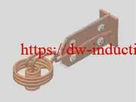
Induction Brazing Coils
Custom Induction Brazing Coils for Industrial Metal Joining
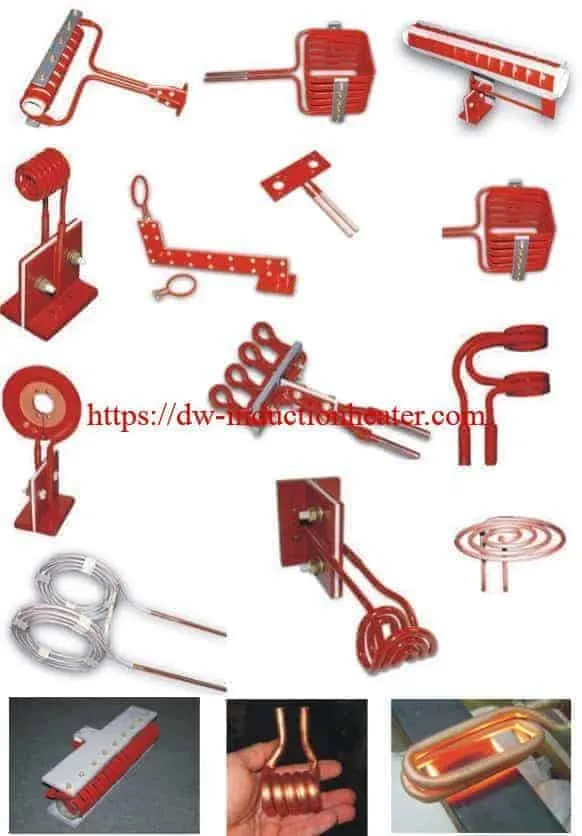
Quick Answer: Induction brazing coils are specially designed copper inductors that generate alternating magnetic fields to heat metal joints for brazing. HLQ Induction Equipment Co., Ltd. provides custom induction brazing coils for copper tubing, HVAC connections, heat exchangers, carbide tools, stainless steel assemblies, aluminum components, and industrial production lines. Available coil configurations include helical, pancake, U-shaped, split, channel, quick-disconnect, and specialized copper inductors. The correct coil design depends on joint geometry, base materials, brazing filler metal, operating frequency, heating power, coupling distance, cooling requirements, and production cycle time.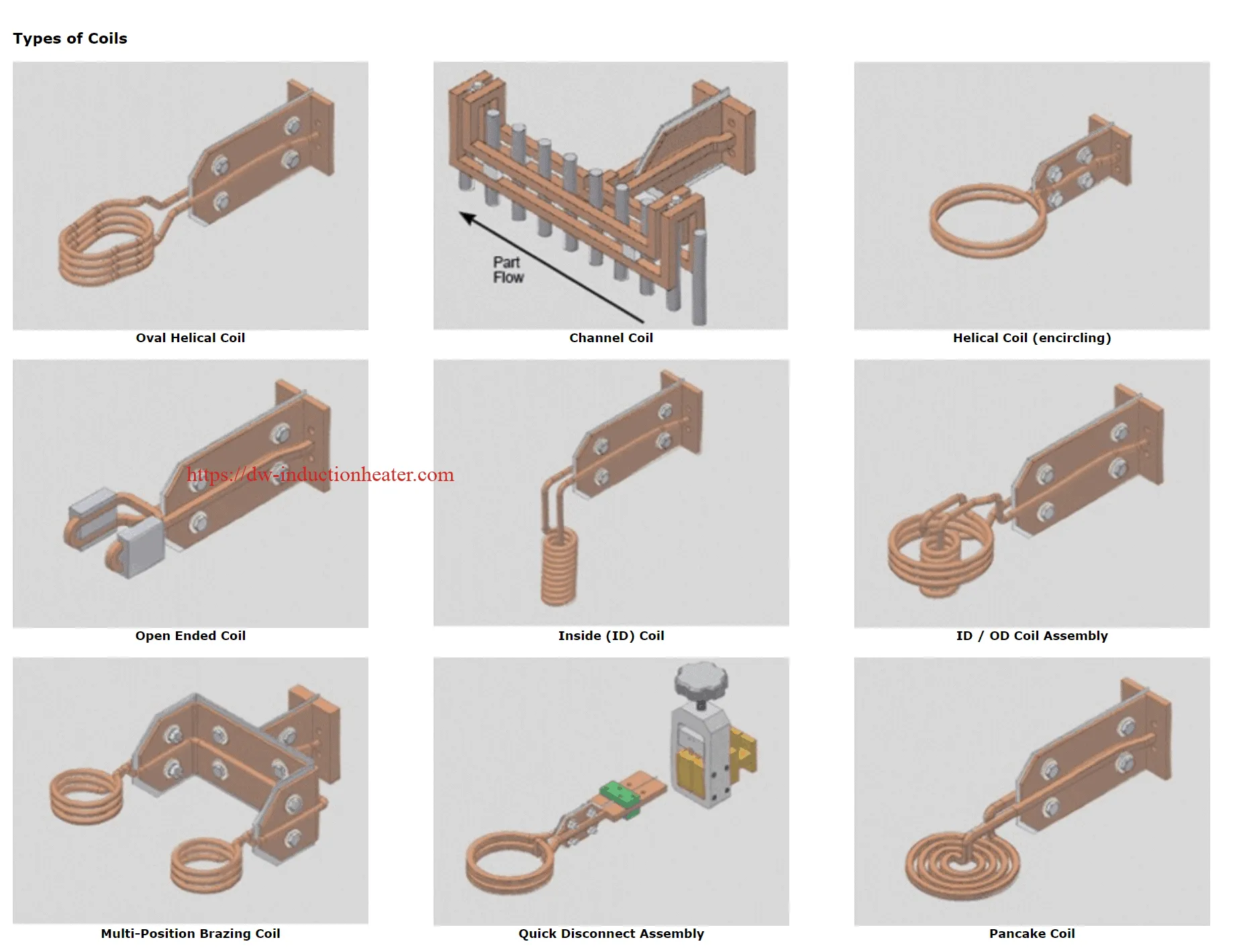
Engineering Selection: An induction brazing coil should be engineered together with the workpiece, brazing filler, fixture, and induction heating power supply. A suitable coil must deliver sufficient heat to the brazing joint while controlling temperature differences between components. The objective is to melt and distribute the filler metal through the joint without melting the base materials.
Table of Contents
- What Is an Induction Brazing Coil?
- Types of Induction Brazing Coils
- Key Applications
- Suitable Materials and Brazing Filler Metals
- Working Principle
- Technical Specifications
- Recommended Coil and Power Supply Selection
- Coil and Fixture Design
- Engineering Calculations
- Induction Brazing Process Workflow
- Coil Cooling and Construction
- Control System and Automation
- Engineering Application Case Study
- Common Problems and Solutions
- Engineering Selection Guide
- Advantages
- Limitations
- Why Choose HLQ Induction Equipment?
- Core FAQs
What Is an Induction Brazing Coil?
An induction brazing coil is a copper inductor designed to generate a controlled alternating magnetic field around a metal joint. When connected to a suitable induction heating power supply, the coil induces electrical currents in conductive components, producing localized heat that allows a compatible brazing filler metal to melt and flow between the joining surfaces.
Unlike fusion welding, induction brazing does not require the base metals to melt. Instead, the brazing filler reaches its liquidus temperature, wets the prepared metal surfaces, and flows into the joint through capillary action.
The induction coil determines where electromagnetic energy is concentrated. Its geometry, operating position, and electrical matching influence heating efficiency, temperature distribution, and brazing repeatability.
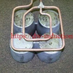
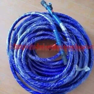
Industrial induction brazing coils are commonly manufactured from high-conductivity copper tubing or specially formed copper conductors. Many high-current designs use internal water-cooling passages to maintain acceptable coil temperatures.

| Function | Engineering Purpose | Effect on Brazing Quality |
|---|---|---|
| Magnetic Field Generation | Produce the alternating electromagnetic field | Determines where induction heating occurs |
| Localized Heating | Concentrate heat near the joint | Limits unnecessary heating of surrounding components |
| Temperature Distribution | Balance heating of the joining components | Supports complete filler metal wetting |
| Electrical Matching | Match the inductor to the power supply | Improves stable operation and useful power transfer |
| Mechanical Positioning | Maintain the specified coil-to-joint relationship | Improves process repeatability |
| Cooling | Remove heat from the coil conductor | Protects coil integrity and operating reliability |
| Production Integration | Allow loading, unloading, and automatic operation | Supports consistent industrial production |
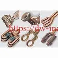
Types of Induction Brazing Coils
Different joint geometries require different induction coil configurations. The most suitable design depends on accessibility, joint dimensions, filler metal placement, and the distribution of metal mass around the brazing area.
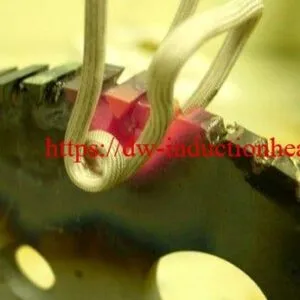
1. Helical Induction Brazing Coils
Helical coils consist of one or more copper turns arranged around a cylindrical joint.
They are commonly used for copper tubes, pipe fittings, cylindrical sleeves, rings, and other components that can be positioned within an encircling coil.
The coil can generate a relatively symmetrical heating field when the joint is correctly centered. However, axial end effects, turn spacing, and nearby conductive components must be considered.
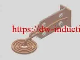
2. Pancake Induction Brazing Coils
Pancake coils use a flat spiral or a related planar conductor arrangement.
They are suitable for accessible flat or nearly flat joints, including carbide tool tips, metal plates, discs, and selected heat exchanger components.
These coils are particularly useful when the workpiece cannot be surrounded by a conventional helical inductor.
3. U-Shaped and Hairpin Brazing Coils
U-shaped or hairpin coils are useful when the brazing joint is accessible from one side but cannot pass through a closed circular coil.
They are commonly considered for closely spaced tube assemblies, localized joints, and components installed near larger supporting structures.
The geometry of the return conductor must be considered because it can influence the magnetic field distribution.
4. Split Induction Brazing Coils
Split coils provide access to fixed or complex assemblies that cannot easily be inserted into a conventional encircling inductor.
They may be useful for large components, assemblies with restricted loading clearance, and production lines with special fixturing requirements.
Reliable electrical contacts and repeatable positioning are especially important for split-coil designs.
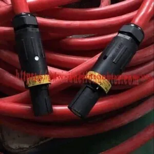
5. Quick-Disconnect Induction Coils
Quick-disconnect designs allow suitable coil assemblies to be changed according to production requirements.
They are useful for manufacturing facilities processing multiple part sizes or different joint geometries.
The connection system must maintain reliable electrical contact, mechanical alignment, and coolant integrity.

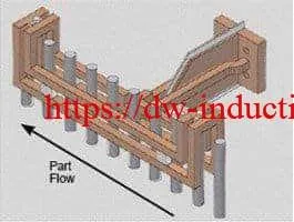
6. Channel and Continuous-Production Coils
Channel coils are designed for applications in which workpieces move through a defined induction heating zone.
They can be considered for continuous or indexed industrial production, particularly when multiple similar components require controlled heating.
Production line speed, workpiece spacing, and consistent joint positioning are important design parameters.

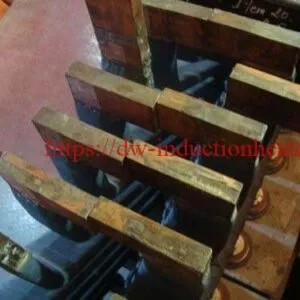
7. ID/OD and Special-Profile Induction Coils
Internal diameter, external diameter, and other custom-profile coils are developed for joints with special geometrical constraints.
These designs may incorporate shaped copper conductors, dedicated fixtures, insulation supports, and magnetic flux concentrators.

| Coil Type | Typical Application | Advantages | Design Considerations |
|---|---|---|---|
| Helical | Copper tube and circular joints | Suitable for circumferential heating | Joint centering, turn spacing, and active length |
| Pancake | Carbide tips and flat assemblies | Accessible surface heating | Heating pattern and coil-to-surface gap |
| U-Shaped | Restricted-access joints | Side access to the heating region | Field balance and conductor return path |
| Split | Fixed or large assemblies | Convenient component access | Contact reliability and mechanical positioning |
| Quick-Disconnect | Multiple product configurations | Convenient coil replacement | Electrical and coolant connection integrity |
| Channel | Continuous and indexed production | Suitable for moving components | Line speed and component spacing |
| Special-Profile | Complex industrial joints | Application-specific heating | Detailed electromagnetic and mechanical design |
Key Applications
Custom induction brazing coils are used in industrial applications requiring controlled joining temperatures, localized heating, and repeatable production cycles.
The coil must be designed around the complete joint assembly rather than only the nominal diameter of one component.
| Application | Base Materials | Recommended Coil Concept | Primary Process Requirement |
|---|---|---|---|
| HVAC Copper Tube Brazing | Copper-to-copper | Helical, split, or U-shaped | Controlled circumferential heating and leak-tight joints |
| Refrigeration Pipe Connections | Copper and brass | Short helical or specialized coil | Joint temperature uniformity |
| Heat Exchanger Manufacturing | Copper, brass, and selected alloys | Multi-position or custom-profile | Repeatable multiple-joint processing |
| Carbide Tool Brazing | Tungsten carbide and steel | Pancake or localized shaped coil | Controlled filler wetting and thermal stress |
| Automotive Components | Steel, copper, and selected aluminum alloys | Application-specific | Consistent process quality |
| Copper-to-Stainless Steel Brazing | Copper and stainless steel | Encircling or customized coil | Balanced heating of dissimilar materials |
| Electrical Component Brazing | Copper and compatible alloys | Localized shaped coil | Limited heating of surrounding assemblies |
| Diamond Tool Brazing | Steel and cutting segments | Pancake or profile coil | Selective heating of the brazing region |
For refrigeration and air-conditioning production, see HLQ’s induction brazing coils and heating solutions for HVAC copper pipes.
Suitable Materials and Brazing Filler Metals
Induction brazing is suitable for many metal combinations, but the brazing filler must be selected according to the base materials, service requirements, joint geometry, and required joining temperature.
The compatibility of the brazing filler is independent of whether an induction coil can successfully heat the joint.
Brazing Filler Metal Selection
Brazing uses a filler metal with a liquidus temperature above 450°C and below the solidus temperature of the base materials.
The filler metal should wet the prepared surfaces and flow through the joint clearance by capillary action.
Induction heating supplies the thermal energy required for brazing, but joint quality also depends on surface preparation, filler composition, oxide control, and cooling conditions.
| Base Materials | Potential Filler Metal Family | Engineering Considerations |
|---|---|---|
| Copper-to-Copper | Suitable Cu-P or Cu-P-Ag alloys | Confirm filler grade, joint clearance, and service environment |
| Copper-to-Brass | Compatible silver-base or approved copper-base brazing alloy | Flux and zinc oxide control may be required |
| Copper-to-Stainless Steel | Qualified silver-base or other compatible filler | Avoid unsuitable phosphorus-bearing fillers on ferrous materials |
| Steel-to-Carbide | Qualified silver-base filler or brazing shim | Control thermal stresses and differential expansion |
| Steel-to-Steel | Application-specific silver-base, copper-base, or other qualified filler | Assess joint strength, atmosphere, and service temperature |
| Aluminum-to-Aluminum | Suitable aluminum-base filler | Control oxide layers and the narrow processing temperature window |
| Mixed Metal Assemblies | Joint-specific qualified filler | Evaluate metallurgical compatibility and thermal expansion |
Important: Copper-phosphorus brazing alloys must not be assumed suitable for steel or nickel-containing base metals. Brittle phosphide formation can compromise joint reliability.
Flux and Surface Preparation
Clean surfaces are essential for successful brazing.
Depending on the filler alloy and base materials, the process may require a suitable flux, protective atmosphere, vacuum conditions, or another qualified oxide-control method.
Some copper-phosphorus alloys provide self-fluxing behavior when joining clean copper-to-copper surfaces, but this property should not be generalized to brass, stainless steel, or other material combinations.
| Factor | Purpose | Potential Defect if Incorrect |
|---|---|---|
| Surface Preparation | Remove contamination and harmful oxides | Poor wetting or incomplete bonding |
| Joint Clearance | Allow suitable capillary flow | Incomplete filler penetration |
| Filler Metal | Provide metallurgical compatibility | Brittleness, corrosion, or inadequate strength |
| Flux or Atmosphere | Control oxide formation | Oxide inclusions and poor flow |
| Heating Uniformity | Bring joint surfaces into the required process window | Uneven wetting and local overheating |
| Cooling Process | Allow stable solidification | Cracking or residual stress |
Working Principle
An induction brazing system uses electromagnetic induction to heat the metal components surrounding a brazing joint.
Alternating electrical current flows through the copper induction coil, generating a changing magnetic field. This field induces electrical currents in the conductive workpiece.
The induced currents generate heat through electrical resistance. Heat also spreads by conduction into adjacent regions of the assembly.
When both joint surfaces reach a suitable brazing temperature, the selected filler metal melts and flows into the joint clearance.
After adequate filler flow, the heating power is stopped and the joint is allowed to cool according to the approved process.
| Step | Process | Engineering Function |
|---|---|---|
| 1 | Electrical Power Supply | Provides electrical energy |
| 2 | Induction Inverter | Generates alternating current at the operating frequency |
| 3 | Induction Brazing Coil | Produces a changing magnetic field |
| 4 | Metal Joint Assembly | Absorbs electromagnetic energy and generates heat |
| 5 | Joint Temperature Increase | Brings the base metal surfaces to the required brazing temperature |
| 6 | Filler Metal Melting | Allows the filler to wet and flow into the joint |
| 7 | Cooling and Solidification | Forms the completed brazed joint |
| 8 | Quality Inspection | Verifies joint acceptance requirements |
Difference Between Induction Brazing and Welding
| Process | Base Metal Melting | Joining Principle |
|---|---|---|
| Induction Brazing | No intentional base metal melting | Filler metal melts and flows by wetting and capillary action |
| Fusion Welding | Base metal is melted | Fusion and solidification of the joint |
| Soldering | No intentional base metal melting | Filler with liquidus at or below 450°C joins the surfaces |
Technical Specifications
HLQ induction brazing coils are available in different configurations according to the application.
Because these are custom-designed inductors, their final dimensions, power compatibility, operating frequency, and cooling requirements depend on the joint geometry and induction power supply.
| Parameter | Specification | Engineering Notes |
|---|---|---|
| Product Name | Custom Induction Brazing Coil | Application-specific copper inductor |
| Manufacturer | HLQ Induction Equipment Co., Ltd. | China |
| Coil Types | Helical, pancake, U-shaped, split, channel, quick-disconnect, and special-profile | Selected according to the joint |
| Conductor Material | High-conductivity copper tubing or formed copper conductors | Material and cross-section selected during design |
| Number of Turns | Single-turn or multi-turn | Project-specific |
| Coil Inner Diameter | Custom | Determined by joint dimensions and clearances |
| Active Heating Length | Custom | Matched to the joint heating zone |
| Operating Frequency | Matched to the induction power supply and workpiece | No universal frequency published for this product category |
| Operating Power | Depends on the generator and heating application | Not a universal standalone coil rating |
| Coupling Distance | Project-specific | Historical page references 3.175–6.35 mm for some helical designs |
| Cooling Method | Typically water cooling for high-current industrial coils | Confirm the selected construction |
| Cooling Water Flow | Engineering-defined | Specify minimum operating flow |
| Cooling Water Pressure | Engineering-defined | Specify permitted pressure range and pressure drop |
| Electrical Connections | Custom terminals or approved quick-disconnect connections | Must match the power supply |
| Mechanical Supports | Application-specific | Maintain the required coil positioning |
| Application Testing | According to project requirements | Verify heating pattern and brazed joint quality |
Recommended Coil and Power Supply Selection
Induction brazing coils are generally selected according to the brazing joint rather than by a fixed coil model number.
The compatible induction heating machine is selected according to the effective heated mass, target brazing temperature, cycle time, material properties, and electrical coupling.
Power and frequency recommendations should be considered preliminary until they are verified using the actual workpiece and coil.
| Application | Material | Recommended Coil | Power Selection | Frequency Selection |
|---|---|---|---|---|
| Small Copper Tube Brazing | Copper-to-copper | Short helical or split coil | Based on joint mass and cycle time | HF/UHF may be considered; verify actual kHz |
| HVAC Copper Fittings | Copper and brass | Helical or U-shaped | Based on fitting mass and thermal balance | Application-specific |
| Carbide Tool Brazing | Tungsten carbide and steel | Pancake or custom-profile | Based on tooling geometry and heating area | Application-specific |
| Copper-to-Stainless Steel | Copper and stainless steel | Customized encircling coil | Consider dissimilar-material heating behavior | Application-specific |
| Heat Exchanger Connections | Copper and compatible alloys | Multi-position or shaped coil | Depends on the number of simultaneous joints | Application-specific |
| Aluminum Tube Brazing | Aluminum alloys | Pancake or special-profile | Controlled to avoid base metal damage | Selected by alloy and geometry |
For localized joining of cutting tools, see the induction brazing carbide tips application.
Coil and Fixture Design
Induction coil design is one of the main factors affecting brazing performance.
A correctly designed coil must provide sufficient heating at the joint while maintaining safe mechanical clearance and suitable electrical matching.
1. Coil-to-Workpiece Coupling Distance
The distance between the copper coil and the workpiece affects electromagnetic coupling.
Reducing unnecessary clearance may improve useful energy transfer, but the minimum gap must also accommodate workpiece tolerances, thermal expansion, electrical insulation, and production movement.
The original HLQ page references approximately 3.175–6.35 mm as a typical design gap for certain helical brazing coils.
This range should be treated as preliminary guidance rather than a universal design standard.
2. Active Heating Length
The active heating length should correspond to the joint geometry and the required temperature distribution.
A coil that is too short may create excessive temperature gradients or require additional heating time for thermal conduction.
A coil that heats an unnecessarily large region may increase the effective heated mass and energy demand.
3. Number of Coil Turns
The number of turns affects inductance, magnetic field distribution, coil current, and electrical matching.
More turns do not automatically improve heating efficiency. The final arrangement should be matched to the inverter and resonant circuit.
4. Joint Positioning
Consistent positioning is important for repeatable brazing.
Even small changes in joint location can modify the coupling conditions and heating distribution.
Dedicated positioning fixtures may be required for high-volume production.
5. Magnetic Flux Concentrators
Where nearby conductive structures could receive unwanted heating, magnetic flux concentrators may help control the field distribution.
Ferrite or other suitable materials must be selected according to frequency, temperature, magnetic properties, and mechanical conditions.
6. Dissimilar-Material Brazing
For copper-to-steel or copper-to-stainless steel brazing, the two components may heat differently because their electromagnetic and thermal properties are different.
The coil should be designed to produce a suitable joint temperature rather than assuming equal heating on both sides.
| Parameter | Influence on Brazing | Engineering Requirement |
|---|---|---|
| Coil Geometry | Determines field distribution | Match the complete joint shape |
| Coupling Gap | Affects useful energy transfer | Maintain safe and repeatable clearance |
| Number of Turns | Affects inductance and load matching | Match to the power supply |
| Heating Length | Influences the heated mass | Cover the required joint region |
| Coil Position | Influences temperature symmetry | Use suitable fixtures |
| Flux Concentrator | Can modify magnetic field concentration | Verify material and temperature limits |
| Cooling Circuit | Controls conductor temperature | Specify flow and pressure requirements |
| Mechanical Access | Influences loading and unloading | Allow sufficient clearance |
Engineering Calculations
Engineering calculations provide an initial estimate of the thermal energy and heating power required for a brazing application.
The calculations must be based on the effective heated mass and the actual process conditions.
1. Theoretical Heating Energy
For a simplified sensible-heating calculation:
Q = m × Cp × ΔT
Where:
- Q = Thermal energy, kJ.
- m = Effective heated mass, kg.
- Cp = Approximate mean specific heat capacity, kJ/kg·K.
- ΔT = Temperature increase, K.
2. Example: Copper Brazing Joint
Consider an illustrative copper tube joint with an effective heated mass of 0.20 kg.
Assume that the joint must be heated from 25°C to 725°C within 20 seconds.
For the preliminary calculation, use an approximate mean specific heat capacity of 0.43 kJ/kg·K.
| Parameter | Value | Data Status |
|---|---|---|
| Material | Copper | Illustrative example |
| Effective Heated Mass | 0.20 kg | Assumed |
| Initial Temperature | 25°C | Assumed |
| Target Temperature | 725°C | Assumed |
| Temperature Increase | 700 K | Calculated |
| Mean Specific Heat | 0.43 kJ/kg·K | Approximation |
| Heating Time | 20 seconds | Assumed |
| Theoretical Heating Energy | 60.2 kJ | Calculated |
| Equivalent Thermal Energy | 0.0167 kWh | Calculated |
| Average Useful Thermal Power | 3.01 kW | Calculated before losses |
The calculated useful thermal power is approximately 3.01 kW.
For illustration only, if the overall electrical-to-workpiece heating efficiency is assumed to be 50%, the estimated average electrical input is approximately 6.02 kW.
This is not a measured machine power requirement. Actual input depends on coil coupling, heat losses, material properties, generator efficiency, fixture heating, and the production cycle.
3. Heating Time and Power Relationship
For the same theoretical heat requirement of 60.2 kJ, the average useful thermal power changes with heating time.
| Heating Time | Useful Thermal Power | Electrical Input at Assumed 50% Efficiency |
|---|---|---|
| 10 seconds | 6.02 kW | 12.04 kW |
| 15 seconds | 4.01 kW | 8.03 kW |
| 20 seconds | 3.01 kW | 6.02 kW |
| 30 seconds | 2.01 kW | 4.01 kW |
| 40 seconds | 1.51 kW | 3.01 kW |
Engineering Note: These are simplified thermal calculations, not measured induction brazing performance. They exclude detailed heat distribution, variable material properties, filler-metal heating, and practical machine operating characteristics.
4. Cooling Water Heat Removal
For a simplified water-cooling calculation, the thermal energy removed by the cooling circuit can be estimated from:
P = mflow × Cp × ΔT
Where the water mass flow rate is expressed in kg/s and Cp in kJ/kg·K.
For example, with a water flow of 3 L/min and an 8°C temperature increase, the approximate cooling heat removal is:
P ≈ 1.67 kW
This is an illustrative calculation rather than the required cooling capacity of any specific HLQ coil.
| Parameter | Illustrative Value |
|---|---|
| Cooling Medium | Water |
| Water Flow | 3 L/min |
| Water Temperature Increase | 8°C |
| Specific Heat Capacity | Approximately 4.18 kJ/kg·K |
| Calculated Heat Removal | Approximately 1.67 kW |
Induction Brazing Process Workflow
Successful induction brazing requires more than an appropriately designed induction coil.
The complete process must control joint preparation, filler placement, heating, cooling, and quality inspection.
| Step | Operation | Engineering Objective |
|---|---|---|
| 1 | Material Identification | Confirm base metal grades |
| 2 | Surface Preparation | Remove contamination and harmful oxides |
| 3 | Joint Assembly | Maintain the specified fit and clearance |
| 4 | Filler Placement | Position the approved brazing filler metal |
| 5 | Coil Positioning | Maintain the required heating geometry |
| 6 | System Inspection | Verify cooling and electrical protection |
| 7 | Induction Heating | Bring the joint into the brazing temperature range |
| 8 | Filler Metal Flow | Allow complete wetting and capillary distribution |
| 9 | Controlled Cooling | Allow joint solidification |
| 10 | Quality Inspection | Verify visual, mechanical, or leak-test requirements |
Coil Cooling and Construction
Industrial induction brazing coils often carry high alternating currents and operate close to hot metal components.
Many designs therefore use water-cooled copper tubing.
The cooling circuit must remove heat generated by electrical losses and heat transferred from the workpiece.
Cooling Water Requirements
The necessary coolant flow depends on the coil current, conductor dimensions, cooling passage geometry, pressure drop, and expected heat rejection.
Cooling-water requirements should be defined for each completed coil design.
| Component | Design Requirement | Verification |
|---|---|---|
| Copper Conductor | Suitable electrical and mechanical dimensions | Dimensional inspection |
| Cooling Passages | Adequate water flow | Flow test |
| Electrical Connections | Reliable current transfer | Connection inspection |
| Cooling Connections | No unacceptable leakage | Pressure or leak test |
| Mechanical Supports | Stable coil positioning | Mechanical inspection |
| Electrical Insulation | Appropriate electrical clearance | Insulation inspection |
| Cooling Protection | Detect inadequate cooling conditions | Functional protection test |
Control System and Automation
An induction brazing coil is part of a complete heating system. The power supply, temperature monitoring, fixtures, and automation equipment determine how the heating cycle is controlled.
Depending on the installation, the system may include programmable power control, cycle timers, temperature monitoring, automated component movement, and PLC integration.
| Function | Purpose | Engineering Consideration |
|---|---|---|
| Power Control | Adjust heating power | Verify actual loaded power response |
| Heating Timer | Control heating duration | Define repeatable cycle parameters |
| Temperature Monitoring | Measure the brazing region | Sensor location and calibration |
| Workpiece Positioning | Maintain repeatable coil alignment | Fixture tolerance and movement |
| Automatic Handling | Improve production consistency | Loading and unloading requirements |
| PLC Integration | Coordinate heating with production equipment | Application-specific control scope |
| Cooling Monitoring | Protect coil and power electronics | Flow and temperature protection |
| Process Recording | Support quality assurance | Record relevant process variables |
Engineering Application Case Study
Induction Brazing of Copper Tubing with a Custom Coil
HLQ has published an induction brazing application involving copper tubing and a DW-UHF-10kW induction heating system.
The objective was to heat a copper tube connection to the required brazing temperature and demonstrate controlled filler metal flow.
The published test used an available split laboratory coil. The application involved heavy-wall 5/16-inch copper tubing and brazing paste.
| Parameter | Published Application Information |
|---|---|
| Application | Copper tubing induction brazing |
| Equipment | DW-UHF-10kW induction heating system |
| Rated Equipment Power | 10 kW |
| Test Workpiece | Heavy-wall 5/16-inch copper tubing |
| Heating Coil | Available split laboratory coil |
| Brazing Material | 505 alloy brazing paste, as reported |
| Temperature Reference | Approximately 815°C |
| Published Heating Cycle | Approximately 5.0–5.2 seconds |
| Temperature Verification | Temperature-indicating paint referenced in the test |
| Final Production Coil | Separate design review required for the complete assembly |
The reported trial demonstrated filler metal flow after approximately 5.0–5.2 seconds of induction heating.
However, the published test was performed with an available laboratory coil. The final production coil for the complete assembly required further design work.
The source also discussed possible magnetic field concentration to reduce unwanted heating of nearby steel components.
This example demonstrates why brazing coil design must consider surrounding conductive structures, joint access, and assembly geometry.
Data Qualification: The values above are taken from a separate HLQ-published application. They do not establish guaranteed heating time, temperature accuracy, or power requirements for every induction brazing coil.
See the complete induction brazing copper tubing case study for the original application description.
Common Problems and Solutions
Induction brazing defects may result from heating conditions, joint design, filler selection, material contamination, or inconsistent workpiece positioning.
| Problem | Possible Cause | Recommended Solution |
|---|---|---|
| Incomplete Filler Flow | Insufficient joint temperature or poor wetting | Verify temperature, filler compatibility, and surface preparation |
| Uneven Heating | Incorrect coil geometry or positioning | Review field distribution and fixture alignment |
| Excessive Heating Time | Poor coupling or excessive heated mass | Review coil design and useful power delivery |
| Local Overheating | Excessive magnetic field concentration | Modify coil geometry or heating parameters |
| Joint Voids | Contamination, poor filler distribution, or unsuitable joint clearance | Review cleaning, assembly fit, and brazing procedure |
| Weak Brazed Joint | Incorrect filler metal or poor metallurgical compatibility | Verify filler specification and joint requirements |
| Coil Overheating | Inadequate cooling or excessive electrical losses | Stop heating and inspect the cooling and electrical system |
| Coil Leakage | Damaged copper tubing or failed connection | Remove the coil from service and repair according to an approved procedure |
| Generator Instability | Electrical mismatch or connection problem | Verify coil and matching-network compatibility |
| Inconsistent Production Quality | Variable joint positioning or heating conditions | Improve fixtures and validate the process recipe |
Engineering Selection Guide
Selecting a suitable induction brazing coil requires an evaluation of the complete joining process.
Step 1: Identify the Base Materials
Determine the actual material grades, wall thicknesses, dimensions, and thermal properties of the joining components.
Step 2: Select the Brazing Filler
Choose a filler metal compatible with both base materials and the intended service conditions.
Confirm its melting range, wetting behavior, and flux or atmosphere requirements.
Step 3: Review the Joint Geometry
Evaluate the joint type, overlap length, clearance, surrounding components, and available coil access.
Step 4: Define the Brazing Temperature
Establish the required temperature range according to the filler metal and base material limitations.
Step 5: Determine Heating Time and Production Rate
Specify the required heating cycle and the number of joints processed per hour.
Include component handling and any additional production operations.
Step 6: Select the Coil Configuration
Choose a helical, pancake, split, U-shaped, channel, or custom-profile coil according to joint accessibility and required field distribution.
Step 7: Match the Power Supply
Verify the available induction power, operating frequency, resonant matching, and required coil current.
The coil should not be selected independently of its electrical system.
Step 8: Design the Cooling System
Specify the coolant flow, permitted pressure, inlet temperature, and relevant protection functions.
Step 9: Validate the Heating Process
Use representative assemblies to check heating behavior, filler flow, and joint quality.
Step 10: Confirm Production Repeatability
Verify the heating cycle, workpiece positioning, cooling performance, and applicable quality acceptance requirements.
| Selection Factor | Required Engineering Information |
|---|---|
| Base Materials | Material grades and compatibility |
| Workpiece Geometry | Dimensions, thicknesses, and assembly drawing |
| Joint Design | Joint type, overlap, and clearance |
| Brazing Filler | Alloy grade and melting range |
| Flux or Atmosphere | Required oxide-control method |
| Brazing Temperature | Target joint temperature |
| Heating Time | Required process duration |
| Production Rate | Joints per hour or production cycle |
| Induction Generator | Power supply model and rating |
| Operating Frequency | Compatible frequency range |
| Cooling Conditions | Available coolant flow, pressure, and temperature |
| Quality Requirements | Leak testing, joint strength, or other acceptance criteria |
Advantages
Custom induction brazing coils provide several potential advantages when correctly designed and matched to the complete heating system.
| Advantage | Engineering Benefit |
|---|---|
| Localized Heating | Concentrates useful heating near the joining area |
| Repeatable Heating | Supports consistent cycles when power and positioning are controlled |
| Custom Geometry | Accommodates different joint shapes and access restrictions |
| Process Automation | Supports integration with production equipment |
| No Direct Burner Flame | Eliminates the need for a torch flame at the workpiece |
| Flexible Coil Configurations | Allows specialized heating arrangements |
| Controlled Heat Distribution | Can reduce unwanted heating of surrounding components |
| Process Data Integration | Supports monitoring and quality assurance when suitable controls are used |
Limitations
Induction brazing coil performance depends on the complete joint assembly and heating system.
| Limitation | Engineering Consideration |
|---|---|
| Joint-Specific Design | A coil optimized for one assembly may not be suitable for another |
| Electrical Matching | The inductor must be compatible with the power supply |
| Mechanical Clearance | Workpiece loading and thermal expansion must be considered |
| Cooling Requirements | High-current coils may require reliable water cooling |
| Material Differences | Dissimilar metals may require special heating arrangements |
| Filler Compatibility | Induction heating cannot compensate for an unsuitable brazing alloy |
| Joint Preparation | Contamination and oxide layers can prevent proper filler wetting |
| Process Validation | Critical applications require representative testing |
Why Choose HLQ Induction Equipment?
HLQ Induction Equipment Co., Ltd. provides industrial induction heating systems and custom induction coil solutions for different metalworking applications.
Successful induction brazing requires coordination between the induction coil, power supply, base materials, filler metal, and production process.
Application-Specific Coil Design
Different coil geometries can be developed for copper tubes, carbide tools, heat exchangers, and other joining applications.
Induction Power Supply Matching
The coil design can be reviewed together with the induction generator, operating frequency, and resonant matching requirements.
Industrial Brazing Integration
Custom coils can be incorporated into suitable manual, semi-automatic, or automated brazing systems.
Coil Construction and Cooling
Electrical connections, copper conductor dimensions, mechanical supports, and cooling requirements can be considered during the design process.
Engineering Documentation
Depending on the project scope, the selected design may require dimensional drawings, electrical compatibility review, cooling specifications, and application testing.
Core FAQs
1. What is an induction brazing coil?
An induction brazing coil is a copper inductor designed to generate an alternating magnetic field around a metal joint. The field produces localized heating, allowing a compatible brazing filler metal to melt and join the base materials.
2. What materials can induction brazing coils be used for?
Induction brazing coils can be used with copper, brass, steel, stainless steel, suitable aluminum alloys, carbide tools, and other electrically conductive assemblies. The filler metal and joint design must be compatible with the base materials.
3. What types of induction brazing coils are available?
Common types include helical, pancake, U-shaped, split, channel, quick-disconnect, and custom-profile induction coils. The correct design depends on the joint geometry and production requirements.
4. How is the correct induction brazing coil selected?
Selection depends on the base materials, joint dimensions, filler metal, brazing temperature, heating cycle, power supply, operating frequency, mechanical clearance, and cooling requirements.
5. What is the ideal gap between the coil and workpiece?
There is no universal gap. The original HLQ page references approximately 3.175–6.35 mm for certain helical brazing coil designs. Actual clearance should be determined from electromagnetic coupling, mechanical tolerances, insulation, thermal expansion, and production handling requirements.
6. How many turns should an induction brazing coil have?
The required number of turns depends on coil geometry, electrical matching, field distribution, and the workpiece. Single-turn and multi-turn coils are both used, depending on the application.
7. What induction frequency is suitable for copper brazing?
The operating frequency depends on copper tube diameter, wall thickness, joint mass, coil geometry, and required heating time. High-frequency induction systems are often considered for small copper tube joints, but the actual frequency must be selected for the specific application.
8. Can induction brazing join copper to stainless steel?
Yes. Induction brazing can join copper to suitable stainless steel components when the filler metal, joint design, and heating conditions are correctly selected. The different electromagnetic and thermal properties of the materials must be considered.
9. Why is the brazing filler metal important?
The filler metal must wet the base materials and flow through the joint at a temperature below the base-metal solidus. An unsuitable filler may cause poor bonding, brittle phases, corrosion problems, or inadequate joint strength.
10. Do induction brazing coils require water cooling?
Many industrial induction brazing coils use water-cooled copper tubing because they carry high alternating currents and operate close to hot workpieces. Cooling requirements depend on the specific coil design and operating conditions.
11. Why does an induction brazing coil produce uneven heating?
Uneven heating may result from unsuitable coil geometry, inconsistent coupling distance, incorrect positioning, nearby conductive structures, or different material properties. The coil and process should be evaluated together.
12. Can induction brazing coils be used in automated production?
Yes. Suitable coils can be integrated with automated positioning systems, PLC controls, cycle timers, temperature monitoring, and production handling equipment. The complete process must be validated for repeatable joint quality.
Technical References and Engineering Review
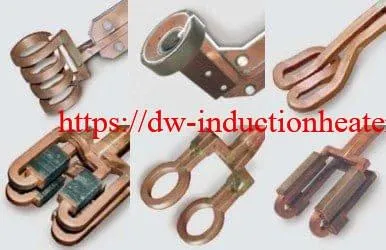
The original HLQ product page also provides technical reference documents covering induction coil design principles.
| Item | Information |
|---|---|
| Manufacturer | HLQ Induction Equipment Co., Ltd. |
| Product Category | Custom Induction Brazing Coils |
| Primary Applications | Industrial metal joining and brazing |
| Electrical Specifications | Application-dependent |
| Engineering Calculation Data | Illustrative estimates unless otherwise identified |
| Application Test Data | Separately identified HLQ-published copper tubing test |
| Last Content Review | October 2026 |
Engineering Disclaimer: Custom induction brazing coil performance depends on the complete heating system, base materials, filler metal, joint geometry, operating frequency, electrical power, cooling conditions, and production requirements. The calculations and examples presented here are intended for engineering selection guidance. Final coil dimensions, power compatibility, heating cycles, and brazing results must be verified for the specific application.
Induction Heating Coil Design and Basic Design