

Induction Weld Heater-Induction PWHT Machine
Induction Weld Heater and PWHT Machine: MYD Series
Quick Answer
This HLQ page presents MYD induction weld-heating equipment with six published output ratings from 40 to 120 kW. The original table lists 2–30 kHz output frequency, while the page describes flexible coils, insulation, K-type thermocouples and recorder options for pre-weld and post-weld heating. A required temperature cycle must come from the material, joint and approved procedure. Several source-page values conflict, so the current configuration requires specification review.

Table of Contents
- What is the Induction Weld Heater and PWHT Machine?
- Key Applications
- Suitable Materials
- Working Principle
- Technical Specifications
- Recommended Model Selection
- Process Workflow
- Common Problems and Solutions
- Engineering Selection Guide
- Advantages and Limitations
- Why Choose HLQ?
- 6 Core FAQs
What is the Induction Weld Heater and PWHT Machine?
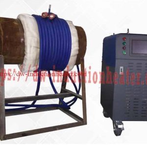
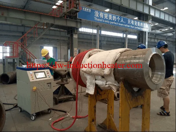
It is an induction heating system presented for localized heating of welded metal workpieces before welding and for related post-weld heat treatment (PWHT). The original page lists a power cabinet, induction coil, connection cable, insulation blanket, K-type thermocouple and temperature-recorder option. The heater supplies heat; it does not perform the weld.
The published six-model table and broader MYD/MYDS comparison describe different levels of product information. A series-wide figure should not automatically be assigned to an individual cabinet.
Key Applications
| Application | Original-page basis | Job-specific decision |
|---|---|---|
| Pre-weld heating | Pre-weld, pipe and steel-structure heating are named. | Set the required temperature, heated band and measurement points. |
| Post-weld heat treatment | PWHT and stress-relief heating are named. | Confirm the applicable thermal cycle and recording requirements. |
| Steel pipeline and sheet work | Steel pipeline, steel structure and steel sheet are listed. | Check grade, thickness, geometry and access. |
| Other local metal heating | Coating, bending and fitting-related heating are listed. | Validate a suitable coil and process for the specific workpiece. |
HLQ groups related products in its induction PWHT machine range.
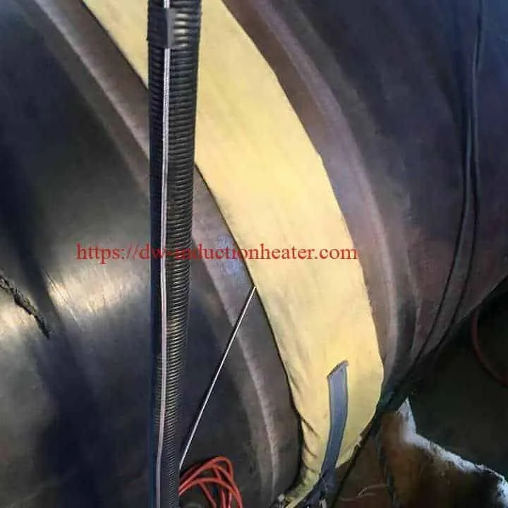
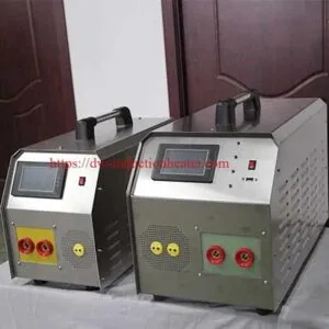
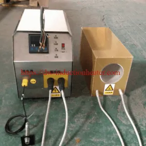
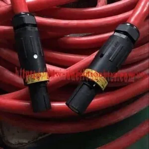
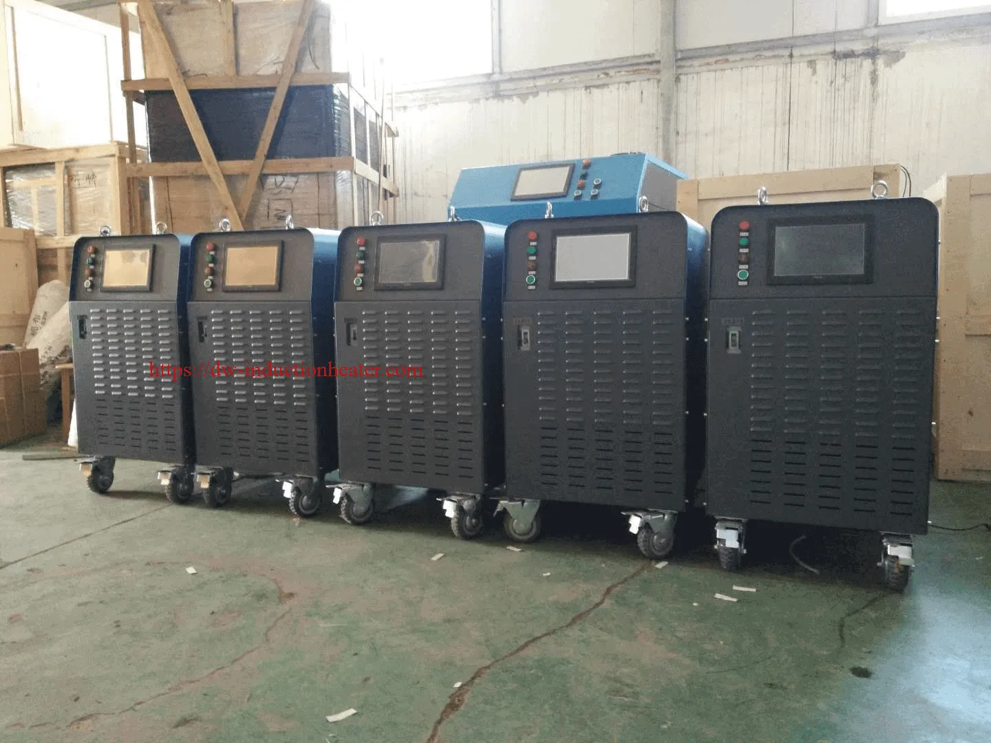
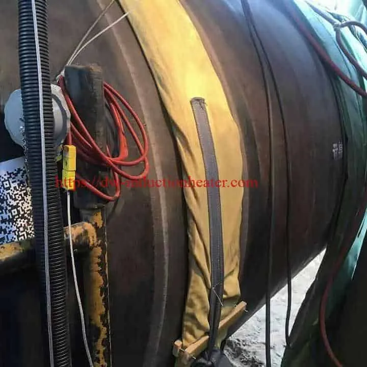
The following PNG uses four original gallery images for visual context. It is not a verified customer case or performance report.

Suitable Materials
Induction heating requires a conductive workpiece and effective coupling between the coil and the intended heating area. The original text specifically names steel pipeline, steel structure and steel sheet. It does not provide an approved material-grade list.
| Workpiece | Source-page evidence | Missing information |
|---|---|---|
| Steel pipeline | Named in the application text. | Pipe grade, wall thickness and joint procedure. |
| Steel structure | Named in the text and represented by a metal-joint image. | Section dimensions and treatment requirement. |
| Steel sheet | Named in the text. | Thickness and heated-band dimensions. |
| Other metal workpieces | Described broadly on the original page. | Material compatibility and suitable process are not established here. |
Working Principle
The MYD power unit drives alternating current through an induction cable positioned around or near the target metal. The changing magnetic field induces currents in the conductive workpiece, generating local heat. Insulation can be part of the setup, while K-type thermocouples provide temperature measurements for the chosen control and recording arrangement.
HLQ describes the underlying method in its basic induction heating principle guide. Coil placement, workpiece geometry and material influence the resulting temperature profile.
| Element | Function | Source boundary |
|---|---|---|
| MYD power unit | Supplies induction output. | Six ratings appear in the main table. |
| Induction cable or clamp coil | Couples heating energy to the target area. | Air-cooled and water-cooled variants are listed. |
| Insulation blanket | Part of the source-listed heating setup. | Two blanket sizes appear in the accessories table. |
| K-type thermocouple | Measures temperature at selected points. | Sensor and cable entries are listed; accuracy is not independently verified. |
| Recorder option | Documents a temperature cycle if fitted. | The original page uses conflicting recorder identifiers. |
Technical Specifications
The following are values published on this page, not independently measured results. Shared rows in the original table do not clearly map machine size, weight, heating size or cooling type to each individual model.
| Model | Listed output power | Listed input current |
|---|---|---|
| MYD-40KW | 40 kW | 60 A |
| MYD-50KW | 50 kW | 75 A |
| MYD-60KW | 60 kW | 90 A |
| MYD-80KW | 80 kW | 120 A |
| MYD-100KW | 100 kW | 150 A |
| MYD-120KW | 120 kW | 180 A |
| Parameter | Published entry | Interpretation limit |
|---|---|---|
| Input voltage | Three-phase 380 VAC default; three-phase 220 VAC and 440 VAC optional | Original table labels the voltage row “Input Power.” |
| Supply frequency | 50/60 Hz | Listed beneath the main table. |
| Output frequency | 2–30 kHz | No model-specific operating frequency is provided. |
| Heating-size entry | Approximately 100–1500 mm diameter | No individual model assignment or wall thickness is stated. |
| Maximum-temperature entry | 900°C | Not a prescribed PWHT setpoint. |
| Heating-speed entry | 5–400°C/min | No workpiece or test conditions are supplied. |
| Machine-size entry | 800 × 560 × 1350 mm | Not assigned to all six individual models. |
| Packing-size entry | 900 × 660 × 1560 mm | Source does not map it by model. |
| Weight entries | 120 kg net; 155–260 kg gross with parts | Individual model and package mapping are unclear. |
| Control entries | 6 channels; “10 curves recorder” | Recorder wording is ambiguous. |
| Other output-power wording | 2–40 kW | Conflicts with the main 40–120 kW model table. |
| Other heating-temperature wording | -30°C to 900°C | The negative value appears in a heating-temperature line; its meaning is unresolved. |
| Other cable-length wording | 10–45 m | Other series and accessory tables list different lengths. |
| Ambient-condition claim | -10°C to 40°C | A source claim without model-specific verification here. |
| Temperature-control claim | ±3°C | Measurement method and test conditions are not given. |
Two original catalogue graphics remain linked for source review. Their branding and some numerical ranges differ from this page’s MYD text table, so they are not displayed as product specification images.
Original image links: catalogue image one and catalogue image two.
Recommended Model Selection
Use the six published power ratings for preliminary screening. Final selection requires the material, joint dimensions, heated band, treatment cycle, available electrical supply and actual cooling configuration.
| Model group | What the page establishes | What remains to check |
|---|---|---|
| MYD-40KW / 50KW / 60KW | 40, 50 and 60 kW are listed in the main table. | Current cabinet data, coil fit and required thermal cycle. |
| MYD-80KW | 80 kW is listed in the main table. | Heating load, temperature channels and cable arrangement. |
| MYD-100KW / 120KW | 100 and 120 kW are listed in the main table. | Cooling type and utilities; the series table also mentions water cooling at 100 kW and above. |
| Entry | MYD | MYDS |
|---|---|---|
| Power ceiling | ≤360 kW | ≤360 kW |
| Separate power-range entry | 10–360 kW | 2.5–360 kW |
| “PLC” entry, unit unspecified | 10 | 4.3 |
| Cooling wording | Air cooling; water at ≥100 kW | Air cooling; water at ≥100 kW |
| Coil-cooling wording | Air for preheat; water for PWHT | Air |
| Maximum-temperature entry | 900°C | 600°C |
| Coil-length entry | 10–50 m | 30–80 m |
| PWHT application marked in source matrix | Yes | No |
The series-wide entries above are not a per-model configuration sheet. For a pipeline-oriented product presentation, see HLQ’s pipeline weld-preheating machine page.
Process Workflow
This is an illustrative engineering workflow. The original page does not publish a qualified ramp, hold or cooling cycle for a named steel grade and joint.
- Identify the metal, welded joint and applicable preheat or PWHT procedure.
- Check the power unit, coil, cooling configuration and temperature-measurement equipment.
- Set up insulation, induction cable and thermocouples at the procedure’s required locations.
- Apply the specified heating and holding cycle while monitoring the required points.
- Cool as specified and retain the required temperature record.
- Review the record before releasing the workpiece through the project process.


HLQ lists flexible induction cable coils for weld preheating and PWHT as a related product.
Common Problems and Solutions
These are general setup checks, not diagnoses of faults in the equipment shown on this page.
| Observed issue | First checks | Why it matters |
|---|---|---|
| Slow temperature rise | Heating load, available supply, coil coverage and insulation. | The source’s heating-speed range has no defined test conditions. |
| Uneven readings across a weld | Coil spacing, heated-band coverage and sensor locations. | Geometry and measurement placement affect the observed profile. |
| Unstable temperature channel | Thermocouple contact, lead condition and channel assignment. | The page lists K-type sensing but no wiring plan for a specific job. |
| Cooling requirement is unclear | Current model and coil specifications. | The page includes both air- and water-cooling entries. |
| Recorder documentation conflicts | Actual installed recorder and its documentation. | Both R-1006 and ER-1006 appear on the source page. |
Engineering Selection Guide
| Project input | Reason to collect it | Page coverage |
|---|---|---|
| Material grade and weld thickness | Determine the governing thermal procedure and heating load. | No grade-specific data. |
| Part diameter and heated-band dimensions | Determine coil fit and heating area. | Only a broad 100–1500 mm entry. |
| Required temperature cycle | Define ramp, hold, cooling and verification needs. | No qualified cycle. |
| Actual electrical rating | Confirm supply and continuous operating load. | Published voltage/current entries require reconciliation. |
| Air- or water-cooled configuration | Define the coil and site utilities. | Both are mentioned; model mapping is unclear. |
| Temperature channels and recorder | Define monitoring and record requirements. | Six channels listed; recorder naming conflicts. |
The following accessory values are reproduced from the original page. Their appearance in an options table does not mean every item is supplied with every model.
| Item | Published detail |
|---|---|
| Heater entries in accessories table | MYD-40KW, MYD-50KW, MYD-60KW and MYD-80KW |
| Induction cable options | 25 m air-cooled, 25 m water-cooled and 25 m high-temperature cable |
| Insulation blanket option 1 | 1500 × 600 × 50 mm; 800°C entry |
| Insulation blanket option 2 | 900 × 600 × 50 mm; 800°C entry |
| K-type thermocouple | 2 m cable entry |
| Thermocouple extension cable | 10 m entry |
| Coil connection cable | 10 m entry |
| Temperature recorder | ER-1006 in options table; R-1006 elsewhere on page |
For a separate treatment-specific presentation, see HLQ’s induction post-weld stress relieving equipment page.
Advantages and Limitations
| Source-supported characteristic | Limit of evidence |
|---|---|
| Six MYD power ratings appear in the main table. | No per-model heating-time or qualified joint-size test is supplied. |
| Flexible coils, insulation and K-type sensing are listed. | The supplied set and cooling method are configuration-dependent. |
| A six-channel control entry is published. | Channel allocation and verified measurement accuracy are not established for every model. |
| Wheeled cabinets appear in source photos. | Published size and weight are not mapped to each model. |
| The page makes qualitative speed, efficiency and uniformity claims. | No defined comparison tests support the claimed 30–80% energy saving here. |
Why Choose HLQ?
This HLQ page provides a six-model MYD table, a broader MYD/MYDS comparison, accessory entries and original equipment and weld-area images. These materials support an initial review of an induction weld-heating setup. Because several specifications conflict within the page and across nearby pages, the current machine data sheet and applicable weld or PWHT procedure should govern final selection. For a smaller published range, see HLQ’s small portable induction PWHT machine page.

6 Core FAQs
1. Does an induction weld heater perform welding?
No. It supplies heat before or after welding. It does not make the weld.
2. Which MYD models are listed in the main table?
MYD-40KW, MYD-50KW, MYD-60KW, MYD-80KW, MYD-100KW and MYD-120KW.
3. What output frequency does the page list?
The MYD text table lists 2–30 kHz. An original catalogue graphic shows a different range for a differently branded series, so that graphic is not used to redefine the MYD specification.
4. Is every listed MYD unit air-cooled?
The page contains both air-cooling and water-cooling descriptions, including a series entry referring to water cooling at 100 kW and above. The actual model and coil configuration must be checked.
5. Is 900°C the required PWHT temperature?
No. It is a published equipment maximum, not a prescribed temperature for every material and joint.
6. Does the page verify 30–80% energy savings?
No. It states that range without a defined comparison baseline, workpiece or test method.