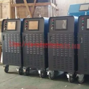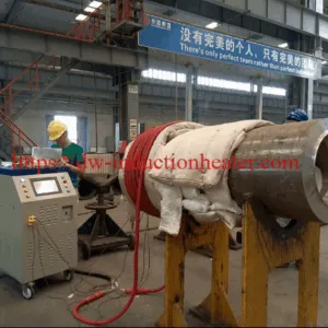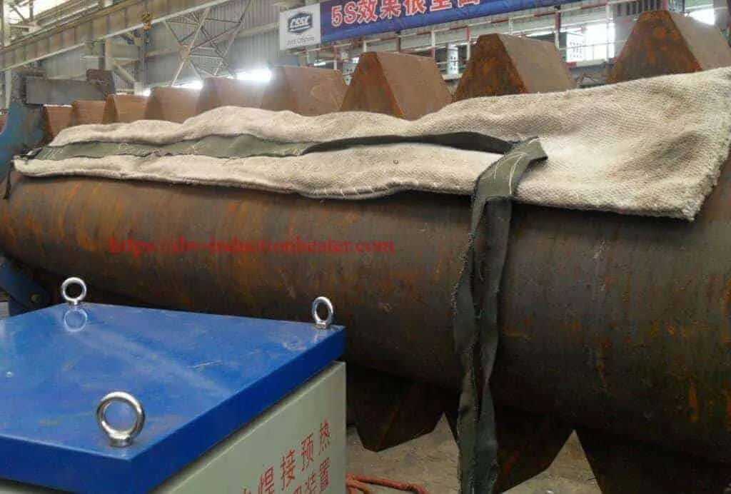


gas-oil pipeline preheat welding machine
MYD Induction Pipeline Weld Preheat Machine for Oil and Gas Pipelines | 40–120 kW
Quick Answer
The HLQ MYD series can heat a defined steel pipeline weld region before welding. The published product table lists six models rated from 40 to 120 kW, with a 2–30 kHz output-frequency range. “Oil and gas” describes pipeline applications on this page; the stated welding-preheat function is to heat the metal pipe joint, not to provide a specified oil or gas fluid-heating duty. The required preheat temperature and measurement method must come from the applicable welding procedure.
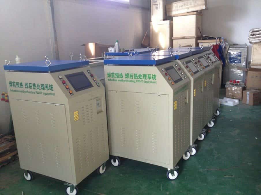
Table of Contents
- What is the MYD Pipeline Weld Preheat Machine?
- Key Applications
- Suitable Materials
- Working Principle
- Technical Specifications
- Recommended Model Selection
- Process Workflow
- Common Problems and Solutions
- Engineering Selection Guide
- Advantages and Limitations
- Why Choose HLQ?
- 6 Core FAQs
What is the MYD Pipeline Weld Preheat Machine?
The MYD is an induction heating arrangement comprising a power unit, a suitable heating coil, temperature sensing, and control or recording components. On this product page, its primary task is to preheat the defined steel pipe region before welding. The page also identifies post-weld heat treatment (PWHT) as another MYD use, but that is a separate procedure after welding. The product is listed in HLQ’s original PWHT Machine category.
A selected MYD power rating does not itself establish the required preheat temperature, weld quality, or suitability for a particular pipeline operating condition.
Key Applications
The original page explicitly names oil, gas, water, and petrochemical pipelines among MYD pipeline-heating fields. For this page, the relevant task is preheating a steel pipe joint before welding; the pipeline service description does not replace a project-specific welding procedure.
| Application named by HLQ | Role of the MYD heater | Process boundary |
|---|---|---|
| Oil pipeline welding | Preheat the defined steel pipe weld region | Pipe and welding procedure determine the required condition |
| Gas pipeline welding | Preheat the defined steel pipe weld region | Site and pipeline requirements must be established separately |
| Water or petrochemical pipeline work | Provide specified pipe-region heating | Do not assume the same preheat procedure applies to every service |
| Post-weld heat treatment | Perform a separately defined heat cycle after welding if required | PWHT is distinct from pre-weld heating |
See HLQ’s induction welding preheating category for related applications.

The following diagram shows application routes named on the source page. It is an illustration, not a verified customer case.

Suitable Materials
For weld-joint heating, the original page names steel pipeline, steel structure, and steel sheet. This product page focuses on steel pipe. It does not provide a qualification table for each steel grade, pipe wall thickness, coating condition, or pipeline service state.
| Source-page workpiece | Stated heating use | Selection information still required |
|---|---|---|
| Steel pipeline | Weld preheat and weld-region heat treatment | Outside diameter, wall thickness, weld location, and approved procedure |
| Steel structure | Weld-joint heating | Section geometry and access |
| Steel sheet | Weld-related heating | Thickness and compatible coil arrangement |
Working Principle
The MYD power unit supplies alternating current to a soft or clamp-type induction coil. The changing magnetic field induces electrical current in the steel pipe, generating heat in the defined joint region. A K-type thermocouple can measure the selected location for control and recording. HLQ explains the general induction heating principle separately.

The diagram below distinguishes pipe-wall heating from pipeline fluid service. It is a functional concept, not an electrical installation drawing.

Technical Specifications
The six model ratings below reproduce the published MYD table. Input currents are stated as published; the original page does not identify their test conditions.
| Published model | Published output power | Published input current | Published output frequency |
|---|---|---|---|
| MYD-40KW | 40 kW | 60 A | 2–30 kHz |
| MYD-50KW | 50 kW | 75 A | 2–30 kHz |
| MYD-60KW | 60 kW | 90 A | 2–30 kHz |
| MYD-80KW | 80 kW | 120 A | 2–30 kHz |
| MYD-100KW | 100 kW | 150 A | 2–30 kHz |
| MYD-120KW | 120 kW | 180 A | 2–30 kHz |
The source table states three-phase 380 VAC as the default, with three-phase 220 VAC and 440 VAC described as options. A separate line states 380 V, three-phase, 50/60 Hz. Confirm the selected model’s electrical configuration.
| Published series-level item | Value stated on the page | How to interpret it |
|---|---|---|
| Maximum stated equipment temperature | 900°C | Not a recommended pipeline weld-preheat temperature |
| Stated heating speed | 5–400°C/min | No test workpiece or conditions supplied |
| Stated heating size | Approximately φ100–1500 mm | Original wording is incomplete; confirm pipe and coil fit |
| Cabinet dimensions | 800 × 560 × 1350 mm | Series-level figure; confirm model-specific construction |
| Packing dimensions | 900 × 660 × 1560 mm | Published series-level figure |
| Net weight | 120 kg | Published series-level figure |
| Gross weight | 155–260 kg with parts; elsewhere 155 kg | Confirm the packed configuration |
| Control and recording | DSP; six channels; ten recorded curves | Confirm the supplied controller and recorder |
| Temperature sensor | K-type thermocouple | Confirm number, placement, and cable length |

The source lists soft and clamp coils. Related coil products appear in HLQ’s induction heating coils category.
| Accessory listed on the source page | Published detail | Point to confirm |
|---|---|---|
| Cable coil | 25 m air-cooled, water-cooled, and high-temperature entries | Compatibility with the chosen MYD unit and welding duty |
| Insulation blanket | 800°C rating; 1500 × 600 × 50 mm or 900 × 600 × 50 mm | Suitability for the actual process |
| K-type thermocouple | One accessory entry gives a 2 m cable | Another page line gives a 5–45 m connecting cable |
| Extension and connection cables | 10 m thermocouple extension and 10 m coil connection cable entries | Actual supplied cable package |
| Temperature recorder | R-1006 in one table; ER-1006 in the accessory list | Exact recorder designation |
Specification cautions: A separate “2–40 kW” bullet conflicts with the main 40–120 kW model table. The page describes air cooling but also lists water-cooled coil options and water cooling in its series comparison. It gives both 10–45 m and 10–50 m coil-length ranges. Its stated ±3°C control tolerance and 30–80% energy-saving range lack sufficient test conditions for a project guarantee.
Recommended Model Selection
The source provides no verified mapping from a pipe size, wall thickness, welding procedure, or required preheat time to one MYD model. Use its published power and input-current figures as candidate ratings, then verify the job’s thermal and electrical requirements.
| Candidate models | Published output power | Published input current | Selection still depends on |
|---|---|---|---|
| MYD-40KW / MYD-50KW / MYD-60KW | 40 / 50 / 60 kW | 60 / 75 / 90 A | Pipe geometry, heat-band width, coil fit, and supply |
| MYD-80KW | 80 kW | 120 A | Required heat input, operating cycle, and cooling package |
| MYD-100KW / MYD-120KW | 100 / 120 kW | 150 / 180 A | Electrical capacity and model-specific cooling |
HLQ’s related induction preheating welding system page describes a broader weld-heating application. Its content should not be used as a pipe-specific model-selection chart.
Process Workflow
The workflow below describes pipe-wall preheating before welding. The actual target temperature, measurement position, and requirements during welding must come from the approved welding procedure. If PWHT is required afterward, it is a separate heating cycle; see HLQ’s induction PWHT system page.
- Define the steel pipe, joint geometry, and approved welding requirements.
- Select and position a compatible coil around the defined preheat region.
- Place the specified temperature sensors and connect the control or recording components.
- Heat the joint region and verify the required preheat condition.
- Carry out welding while maintaining the specified conditions.
- Complete the required inspection and perform a separate PWHT cycle only if the procedure requires it.
This flowchart is conceptual. The product page does not publish one preheat temperature or cycle for all oil and gas pipelines.

Common Problems and Solutions
| Observed issue | Checks to perform | Why the check matters |
|---|---|---|
| Temperature differs around the pipe joint | Review coil position, heat-band width, pipe geometry, insulation, and thermocouple placement | These affect where heat is produced and measured |
| Heat-up time differs from expectation | Check wall thickness, starting temperature, coil arrangement, and available power | The page’s 5–400°C/min claim has no specified test conditions |
| Temperature record appears inconsistent | Check thermocouple attachment, cable connections, channel assignment, and recorder setup | Control and review depend on reliable measurements |
| Coil or power-unit cooling is unclear | Check the selected model and accessory configuration | The source includes both air- and water-cooling references |
| Preheat acceptance cannot be determined | Compare measured temperature with the approved welding procedure | The equipment’s 900°C maximum is not a weld-preheat target |
Engineering Selection Guide
Collect the inputs below before specifying an MYD rating, coil arrangement, power supply, and monitoring package. The original page does not document site clearances or a procedure for each pipeline service condition.
| Engineering input | Reason required | Provided on the original page? |
|---|---|---|
| Pipe material and welding procedure | Define whether preheat is needed and its acceptance condition | No steel-grade-specific procedure |
| Pipe OD and wall thickness | Check coil fit and workpiece heat demand | Only an approximate heating-size range |
| Joint location and heating-band width | Define coil and sensor arrangement | No job-specific drawing |
| Required preheat and monitoring locations | Set and verify the process condition | No universal preheat target |
| Available voltage, current, and cooling | Check equipment compatibility | Electrical options listed; cooling statements conflict |
| Pipeline service and site conditions | Establish the applicable project controls | No site-specific procedure |
The layout is a functional illustration, not a field installation drawing.

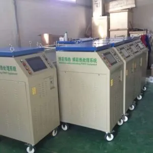
This final gallery image is retained from the source page without assigning it to a documented customer project.

Advantages and Limitations
| Published MYD feature | Limit of the published information |
|---|---|
| Six listed ratings from 40 to 120 kW | No verified pipe-size-to-model selection chart |
| Soft and clamp coil options | Exact coil compatibility and cooling require confirmation |
| K-type temperature sensing and curve recording described | Exact supplied sensor and recorder package is unclear |
| Oil and gas pipeline heating applications named | No verified customer site, preheat temperature, weld result, or cycle time is published on this page |
Weld preheating occurs before welding. HLQ presents pipeline PWHT stress relieving after welding as a related but separate operation.
Why Choose HLQ?
HLQ publishes six MYD model ratings, corresponding input-current values, voltage options, an output-frequency range, series-level dimensions, and coil and temperature-monitoring options. This provides a documented starting point for comparing pipeline weld-preheat configurations. Final suitability depends on the actual pipe, welding procedure, electrical supply, coil package, cooling arrangement, and confirmed model specification.
6 Core FAQs
1. Does “gas-oil” mean this product heats oil or gas inside the pipe?
For this product page, “gas-oil” identifies pipeline applications. The described welding-preheat task is heating the steel pipe weld region; no fluid-heating duty is specified.
2. Which MYD models are listed?
The published table lists MYD-40KW, MYD-50KW, MYD-60KW, MYD-80KW, MYD-100KW, and MYD-120KW.
3. What is the correct pipeline weld-preheat temperature?
The source page does not provide a universal value. The applicable welding procedure must define the required temperature and how it is measured.
4. Does the 900°C maximum specify a preheat setpoint?
No. It is the equipment-page maximum, not a recommended temperature for every pipe weld.
5. Is this MYD system air-cooled or water-cooled?
The page includes both air-cooling descriptions and water-cooling references. Confirm the selected power-unit and coil configuration.
6. Is PWHT included in every pipeline weld-preheat job?
No. PWHT is a separate after-welding cycle performed only when required by the applicable procedure.