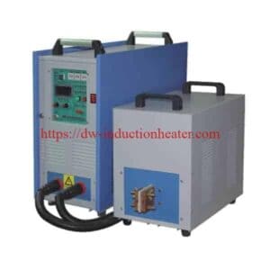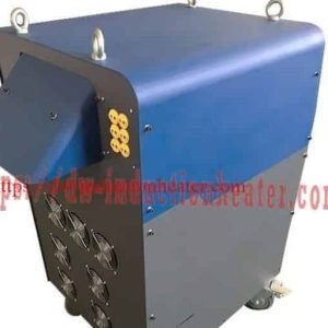
Pipeline PWHT Stress Relieving After Welding
Pipeline PWHT Stress Relieving After Welding
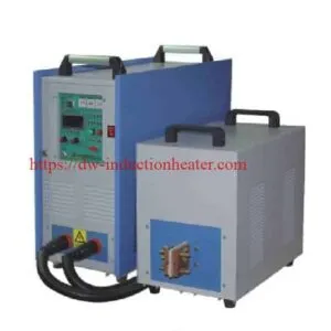
Pipeline PWHT stress relieving after welding is the controlled heating of a welded pipe joint to a qualified soak temperature, holding it there for the specified time, cooling it on a controlled rate, and recording the cycle. HLQ builds this equipment as the MYD series of air-cooled induction heating systems, published at 40 kW, 50 kW, 60 kW, 80 kW, 100 kW and 120 kW, with an output frequency of 2 to 30 kHz, a maximum temperature of 900 °C, and a control tolerance of ±3 °C on up to six K-type thermocouple channels.
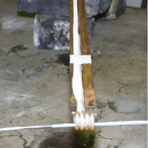
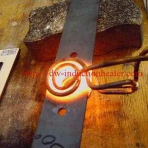
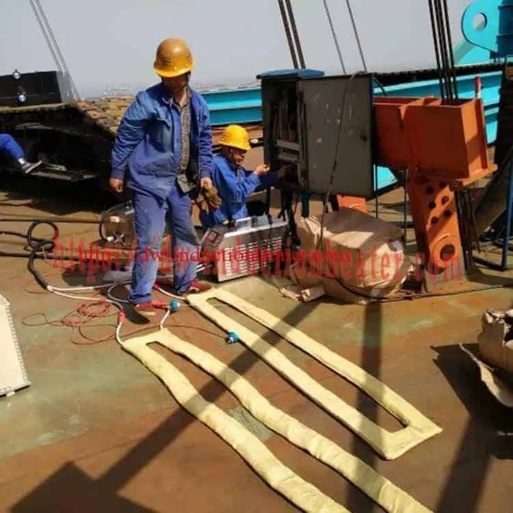
The heat is not applied from outside. A flexible induction cable is wrapped around the joint, the alternating magnetic field it produces drives current through the pipe wall itself, and the resistance of the steel turns that current into heat. The joint is then closed over with an insulation blanket, the thermocouples follow the metal temperature, and the controller runs a programmed ramp, soak and cool cycle with the whole curve recorded.
One published field case shows what the process delivers in measured numbers. On a carbon steel pipe of 880 mm outside diameter and 25 mm wall, with a 480 mm heated band, an 80 kW supply and a 30 m flexible cable, the joint reached the 650 °C soak in an average of 51.2 minutes and held within ±1 °C, with the highest measured temperature at 655 °C and the lowest measured soak temperature at 646 °C. Those figures belong to that joint and that procedure; the approved heat-treatment procedure for the pipe grade, the wall thickness and the code in force govern every other job.
The complete published reference for this equipment family is the MYD series induction heating system catalogue. For the wider field picture, see the published applications of induction PWHT machines in the oil and gas pipelines field.

Quick Answer
The MYD series pipeline PWHT machine heats a welded pipe girth weld to a qualified soak temperature by inducing current directly in the pipe wall, holds it within ±3 °C on six thermocouple channels, cools it on a programmed rate, and records the entire heating curve. Six models are published, from MYD-40KW at 40 kW and 60 A to MYD-120KW at 120 kW and 180 A, all on three-phase 380 V standard input with 2–30 kHz output, 900 °C maximum, a heating rate capability of 5–400 °C/min, and a cabinet of 800 × 560 × 1350 mm weighing 120 kg net on wheels. The supplied system also needs an induction cable coil, an insulation blanket, K-type thermocouples with connection cables, and an R-1006 temperature recorder. The MYD is published as suitable for PWHT; the simplified MYDS variant is published as unsuitable for PWHT and is intended for preheat only.
Selection follows the joint, not the kilowatt figure: pipe grade and soak window first, then wall thickness against the code-limited heating and cooling rates, then the heated band mass, the band width and the pipe circumference, and finally whether a recorded chart per joint is required.
Table of Contents
- What is the Pipeline PWHT Stress Relieving After Welding?
- Key Applications
- Suitable Materials
- Working Principle
- Technical Specifications
- Recommended Model Selection
- Process Workflow
- Common Problems and Solutions
- Engineering Selection Guide
- Advantages and Limitations
- Why Choose HLQ?
- 6 Core FAQs
What is the Pipeline PWHT Stress Relieving After Welding?
The name describes the job and the method at once. Pipeline identifies the workpiece: a steel pipe with a circumferential girth weld. PWHT identifies the process: post weld heat treatment, the controlled reheating of the weld and its heat-affected zone to relieve residual stress and temper the hardened zone next to the bead. Stress relieving is the primary purpose of that heat. After welding fixes the sequence: the joint is heated after the weld is complete and accepted, not before it.
It is a portable station built for one job type. The published description of the MYD series covers weld, bending, piping, coating, fitting, stress relief, pre-weld heat and post-weld heat treatment, and its application list names pipeline oil, pipeline gas, pipeline water and pipeline petrochemical work as the pipeline duties.
The delivered system is a matched set, not a single box:
| Part of the system | Published specification | Role at the joint |
|---|---|---|
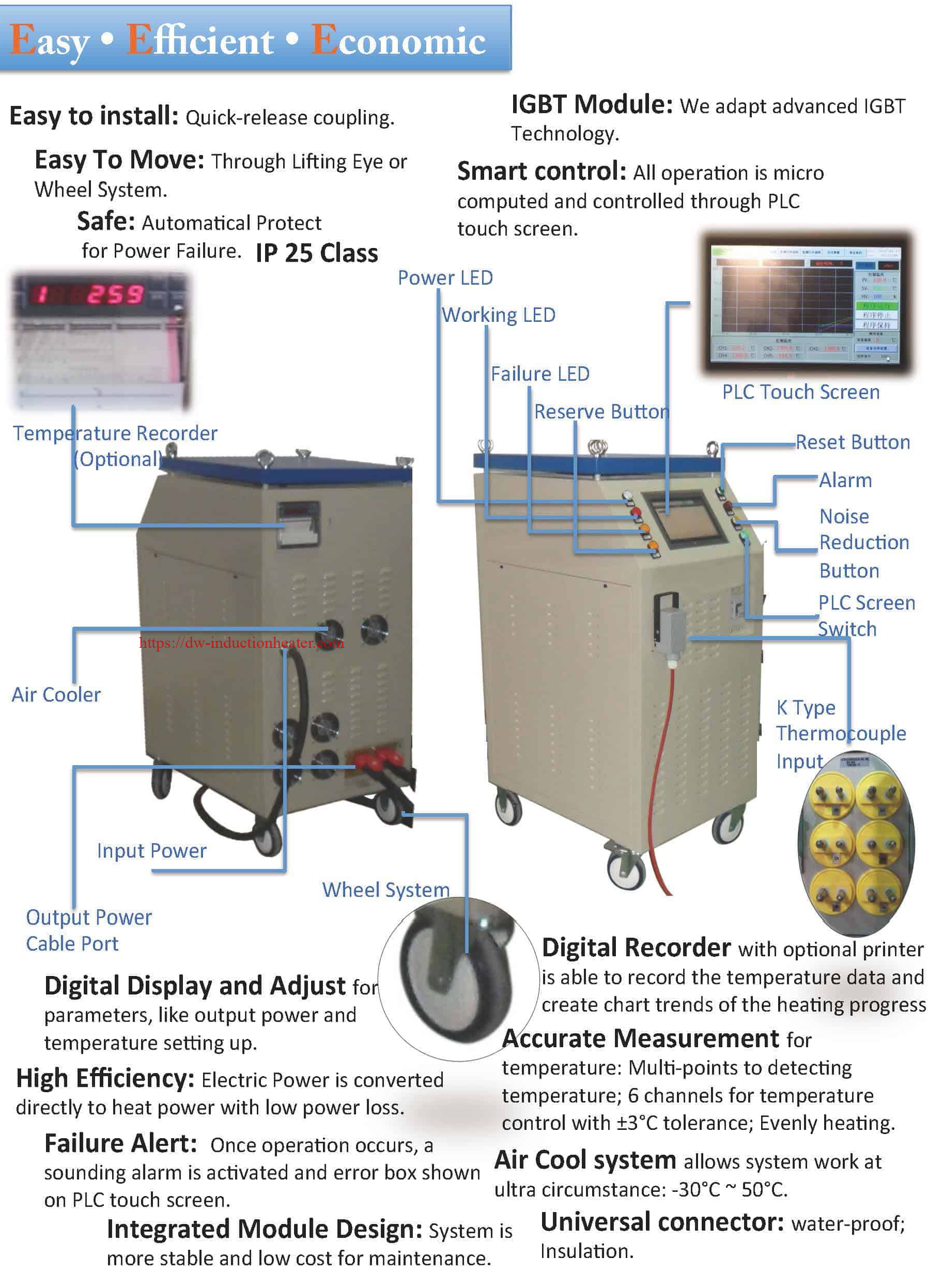
| MYD power unit | 40–120 kW, 2–30 kHz, air cooled, 800 × 560 × 1350 mm, net 120 kg | Supplies the medium-frequency power and runs the cycle program |
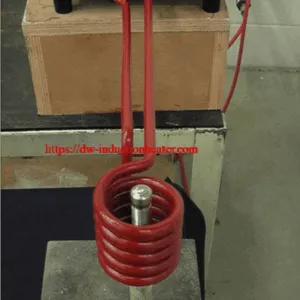
| Flexible induction cable | 10–45 m of high-temperature cable, air cooled; clamp coil or soft coil; water-cooled versions also published | Wrapped around the pipe so the current is induced in the wall |
| Insulation blanket | Ceramic fibre; published sizes 1500 × 600 × 50 mm and 900 × 600 × 50 mm, rated to 800 °C | Keeps the heat in the band and evens the temperature out |
| K-type thermocouples | K type, 5–45 m link cable, plus thermocouple connection cable | Measure the metal temperature for the control loop |
| R-1006 temperature recorder | 6 channels, printer optional | Keeps the independent record for the quality file |
| Connection cable | 10 m published for the coil | Links the coil and the power unit |
Because the geometry of the joint decides how many metres of cable and how large a blanket are needed, the recorder, the cables and the blanket are optional published items rather than fixed contents. The full model and parts data is in the MYD series catalogue, and the blanket itself is specified on the PWHT insulation blanket page.

Where the heat is made
Three consequences follow from the arrangement, and they are the reason induction is used for pipeline PWHT rather than a resistance blanket:
- The heat starts inside the wall. The steel is heated from the inside out, so the surface does not have to be brought to temperature before the core follows.
- The heating is controlled where it matters. A thermocouple in the wall measures the metal, not the air around it, so the loop responds to the pipe rather than to the workshop.
- There is no flame. The published comparison against ceramic pad heating is direct heat, less heat lost, higher speed and higher efficiency, with a published energy saving of 30 to 80 %.
Key Applications
The published application list for this equipment separates preheat, post-weld heat treatment and general heating, and names the pipeline duties explicitly.
| Published application | What it covers | Typical job on this equipment |
|---|---|---|
| Preheat | Heating before welding for coating, bending, fitting and unfitting, and welding itself | Bringing a pipe or a plate edge to the preheat temperature and holding it through the weld |
| Post-weld heat treatment | Tank, boiler or other metal jobs; weld joint heating and heat treatment for steel pipeline, steel structure and steel sheet | Stress relieving a seam after the weld is complete |
| Pipeline heat | Pipeline oil, pipeline gas, pipeline water, pipeline petrochemical and other pipeline material | PWHT of a girth weld in a transmission or distribution line |
| General heating | Mould heating, shipboard, zinc bath, large and irregular metal parts | Thermal assembly heating of bearings, axle sleeves, motor housings |
| Other published duties | Hot drying, factory warming, coating heating, melting of copper, aluminium, tin, zinc and lead | Wherever a controlled heat is needed around a workpiece |
The published list of using fields is broader than oil and gas: petrochemical, oil and gas pipelines, aerospace, shipbuilding, steel, tanks, boilers, vessels, pressure vessels, cylinders, metal structure, spatial structure, railway bridges, electricity and water, mine construction, vehicle manufacturing, nuclear power, mining, plastics processing, energy saving process, mould and screw barrel industries. The pipeline girth weld is one of the best-established of those duties, and it is the duty this page covers. The published catalogue adds five field heating samples on this equipment: hot fitting and unfitting heating, post weld heat treatment, pre-weld heat, heat for coating and painting, and pipeline materials heating.


For the wider pipeline picture, including how these machines are used in the field on oil and gas lines, see the published induction PWHT applications in the oil and gas pipelines field page, and the configured system package is described on the induction PWHT system for oil and gas pipeline welding projects page.
Suitable Materials
PWHT on a pipeline is governed by the metal and the code, not by the machine. The soak temperature, the permitted heating and cooling rates, the heated band width and the recording requirements all come from the approved procedure for the pipe grade.
| Material | Typical PWHT soak | Magnetic at the soak? | Control note |
|---|---|---|---|
| Carbon steel (P-No.1) | 595–650 °C | Yes | Wide window; a standard program is enough |
| P11 (1¼Cr-½Mo) | 650–745 °C | Yes | Recorded soak and a hardness check |
| P22 (2¼Cr-1Mo) | 675–760 °C | Yes | Tighter control is recommended |
| P91 / P92 (9Cr-1Mo-V) | 730–775 °C | Close to the Curie point | Narrow window; the soak must stay below Ac1 |
| Austenitic stainless steel | By specification | No | A non-magnetic load, which the controller tracks automatically |
Two material facts change the way the machine behaves. First, a non-magnetic austenitic load couples very differently from a magnetic steel, so the frequency and the matching have to be set for the actual grade. Second, carbon steel loses its magnetism as it passes the Curie point, near 770 °C, and the electrical load changes with it; a control system that tracks the resonant frequency handles that automatically, while a fixed-frequency system does not.
Those are typical ranges only. The qualified procedure and the current code edition govern, and the machine has to be programmed to the procedure rather than to the table above.
The published heating and cooling rate limits for carbon steel follow the wall thickness of the pipe, not the power of the machine:
| Wall thickness | Maximum heating rate above 427 °C | Maximum cooling rate above 427 °C |
|---|---|---|
| 25 mm | 222 °C/h | 278 °C/h |
| 50 mm | 111 °C/h | 139 °C/h |
| 75 mm | 74 °C/h | 93 °C/h |
| 100 mm and above | 56 °C/h (minimum limit) | 69 °C/h |
The rate figures are 222 × 25 divided by the wall thickness in millimetres for heating and 278 × 25 divided by the thickness for cooling, with a lowest required limit of 56 °C/h. A thicker wall means a slower ramp, which in turn means a longer cycle and a different power requirement. Always check the current edition of the governing code.

Working Principle
The heating happens in the steel, not above it. Three-phase electricity is rectified and inverted by the IGBT stage into medium-frequency alternating current, which is matched to the cable through the compensating circuit. The cable wrapped around the joint produces an alternating magnetic field. That field induces current in the pipe wall, the resistance of the steel turns the current into heat, and the pipe itself becomes the heating element. The insulation blanket keeps the heat inside the band instead of letting it escape to the atmosphere.
The skin depth of the induced current decides how deep the heat goes, and the frequency sets the skin depth. The published reference figures across the MYD band are:
| Material or condition | 2 kHz | 5 kHz | 10 kHz | 20 kHz | 30 kHz |
|---|---|---|---|---|---|
| Carbon steel below the Curie point (ρ 1.6×10⁻⁷ Ω·m, μr ≈ 100) | 0.45 mm | 0.28 mm | 0.20 mm | 0.14 mm | 0.12 mm |
| Stainless steel 304 (ρ 7.2×10⁻⁷ Ω·m, μr = 1) | 9.5 mm | 6.0 mm | 4.3 mm | 3.0 mm | 2.5 mm |
| Carbon steel above the Curie point (ρ 1.2×10⁻⁶ Ω·m, μr = 1) | 12.3 mm | 7.8 mm | 5.5 mm | 3.9 mm | 3.2 mm |
The calculation behind the table is δ = 503 · √(ρ / (μr · f)), with ρ the electrical resistivity, μr the relative permeability and f the frequency in hertz. Below the Curie point the heat is generated in a thin surface layer and conducts through the wall, which is exactly why a code-limited heating rate produces even through-wall temperatures. Above the Curie point the permeability falls to about 1 and the current moves much deeper, so the same skin depth formula applies with a much larger result — and the same power now moves a different amount of energy into the metal.
That is the single most common cause of an unnecessary service call. A drop in output power above roughly 750 °C is normal behaviour, not a fault: the DSP re-tracks the resonant frequency automatically and the machine copes without operator action. The wider control architecture is set out on the IGBT PWHT machine with DSP and PLC control page.
One published comparison between the two heating methods, taken from the MYD literature:
| Item | Induction | Ceramic pad heating |
|---|---|---|
| Heat | Direct | Transfer |
| Insulation | Inner | Outer |
| Heating elements | Less hot | Hot |
| Heating lost | Less | More |
| Speed | High | Low |
| Efficiency | High | Low |
| Uniformity | More | Less |

Technical Specifications
The published model and technical parameter table for the MYD series, with each parameter on the row it belongs to:
| Model | MYD-40KW | MYD-50KW | MYD-60KW | MYD-80KW | MYD-100KW | MYD-120KW |
|---|---|---|---|---|---|---|
| Output power | 40 kW | 50 kW | 60 kW | 80 kW | 100 kW | 120 kW |
| Input current | 60 A | 75 A | 90 A | 120 A | 150 A | 180 A |
| Input power | 3 × 380 VAC (default), 3 × 220 VAC and 3 × 440 VAC optional | |||||
| Output frequency | 2 kHz ~ 30 kHz | |||||
| Input voltage | 380 V, 3 phase, 50/60 Hz | |||||
| Cooling | Air cooled | |||||
| Heating size | ⌀100–1500 mm | |||||
| Heating temperature range | −30 °C to 900 °C | |||||
| Maximum temperature | 900 °C | |||||
| Heating speed | 5–400 °C/min | |||||
| Control | DSP control, PLC touch screen, ±3 °C tolerance | |||||
| Control channels | 6 channels, 10 curves recorder | |||||
| Machine size | 800 × 560 × 1350 mm | |||||
| Packing size | 900 × 660 × 1560 mm | |||||
| Net weight | 120 kg | |||||
| Gross weight with parts | 155–260 kg | |||||
| Main parts | Induction coil · connection cable · K thermocouple · insulation blanket · R-1006 temperature recorder · thermocouple connection cable | |||||
Two notes on the published figures. The general specification list carries the line “Output Power: 2KW ~ 40KW”, which conflicts with the 40 to 120 kW model table above; the model table and the catalogue are the reliable figures, so confirm the rating of the unit being quoted. The same list gives a gross weight of 155 kg against the 155–260 kg range with parts, and gives the K-type thermocouple a 5–45 m link cable where the parts list shows a 2 m cable with a 10 m extension. The coil, the blanket and the recorder are specified separately on the PWHT chart recorder and PWHT flexible cable coil pages.

Published parts and options list
| No. | Published heater and part | Published note |
|---|---|---|
| 1 | MYD-40KW heater | Power unit |
| 2 | MYD-50KW heater | Power unit |
| 3 | MYD-60KW heater | Power unit |
| 4 | MYD-80KW heater | Power unit |
| 5 | 25 m cable coil (air cooling) | Quick heat |
| 6 | 25 m cable coil (water cooling) | — |
| 7 | 25 m cable coil (high temperature) | — |
| 8 | Insulation blanket (800 °C) 1500 × 600 × 50 mm | — |
| 9 | Insulation blanket (800 °C) 900 × 600 × 50 mm | — |
| 10 | K type thermocouple with 2 m cable | — |
| 11 | Thermocouple extension cable 10 m | — |
| 12 | Connection cable for coil 10 m | — |
| 13 | ER-1006 temperature recorder | — |
The optional parts published for the induction heating system are: induction heating power, induction coil (clamp induction coil or soft induction coil), connection cable for the convenient link between the coil and the heating power, temperature controller, PLC touch screen, temperature recorder with printer, K type thermocouple and connection cable, insulation blanket, and other parts.
MYD compared with the MYDS series
| Item | MYD | MYDS |
|---|---|---|
| Power range | 10–360 kW | 2.5–360 kW |
| Touch screen size | 10 in | 4.3 in |
| DSP control | Yes | Yes |
| Cooling type | Air cooling, water ≤100 kW | Air cooling, water ≤100 kW |
| Coil cooling | Air for preheat, water for PWHT | Air |
| Maximum temperature | 900 °C | 600 °C |
| Coil length | 10–50 m | 30–80 m |
| USB | Yes | No |
| Recorder connector | Yes | No |
| Heating curve storage | Yes | No |
| Thermocouple connector | Yes | Yes |
| Remote control | Yes | No |
| Coil connector | Yes | Yes |
The single clearest line in that table is the last one: the MYDS variant is published as not suitable for PWHT. That is the practical dividing line between the two versions, and it is why a pipeline PWHT job needs the MYD.
Two points on the cooling that are published in the same table are worth stating plainly. The published entry reads “Air cooling, Water ≤100 kW”, so the MYD-100KW and MYD-120KW carry water cooling and the smaller models are air cooled — which means a cooling-water supply is needed on site for the two largest machines. And the feature list also publishes that air cooling on this equipment works well at −10 °C to 40 °C. The configuration being ordered should be confirmed in writing.
Published application coverage, MYD against MYDS
| Application | MYD | MYDS |
|---|---|---|
| Preheat | Yes | Yes |
| Weld heat | Yes | Yes |
| PWHT | Yes | No |
| Thermal assembly heating | Yes | Yes |
| Reactor heating | Yes | Yes |
| Tank heating | Yes | Yes |
| Injection mould heating | Yes | Yes |
| Water, gas and oil heating | Yes | Yes |
| Pipeline liquid heating | Yes | Yes |
Published thermocouple accuracy of the R-1006 / ER-1006 recorder
| Thermocouple type | Range (°C) | Accuracy (°C) |
|---|---|---|
| K | −200 to −100 | ±3.3 |
| K | −100 to 1300 | ±2.0 |
| B | 600 to 1800 | ±2.4 |
| E | −200 to 1000 | ±2.4 |
| J | −200 to 1200 | ±2.4 |
| S | −50 to 100 | ±3.7 |
| S | 100 to 300 | ±2.0 |
| S | 300 to 1600 | ±1.5 |
| N | −200 to 1300 | ±3.0 |
| T | −200 to −100 | ±1.9 |
| T | −100 to 380 | ±1.6 |
| R | −50 to 100 | ±3.7 |
| R | 100 to 300 | ±2.0 |
| R | 300 to 1600 | ±1.5 |
| WRe5-26 | 0 to 2300 | ±4.6 |
| WRe3-25 | 0 to 2300 | ±4.6 |
The published note on the recorder is that the accuracy excludes cold junction error. The ±3 °C figure published for the machine is the control tolerance, not the measurement accuracy, and the two should not be quoted as one number.
Recommended Model Selection
Selection for a pipeline PWHT job starts with the joint, not with the kilowatt figure. The four questions that decide the model are the mass of steel in the heated band, the band width and the pipe diameter, the ramp rate the code allows, and whether a recorded chart per joint is required.
| Your job | Published model candidates | Reason |
|---|---|---|
| Single girth weld on a pipe up to ⌀610 × 50 mm, with a recorded chart | MYD-40 | Full control and recording, with enough power for a single joint |
| Pipe ⌀610–⌀1219 mm, or plate seams up to 3 m | MYD-60 / MYD-80 | Power margin for the losses and for a wider heated band |
| Long seams, vessels and heavy sections | MYD-100 / MYD-120 | Higher output on the same control platform |
| Preheat only, no records required | MYDS series | Simpler controller, up to 600 °C |
| Joint requiring a water-cooled coil above 100 kW | MYD with water cooling | The published coil cooling rule is water at and above 100 kW |
A published worked case shows how the power matches a real joint. On the 880 mm OD, 25 mm wall pipe with a 480 mm band, an 80 kW supply with a 30 m cable was used, which sits between the MYD-60 and the MYD-80 rating. The measurement points were at 0, 90, 180 and 270 degrees around the circumference plus two axial edge points.
| Test point | Time to 300 °C | Time to 500 °C | Time to 650 °C | Peak temperature | Final soak temperature |
|---|---|---|---|---|---|
| T1 | 18 min | 34 min | 49 min | 654 °C | 650 °C |
| T2 | 19 min | 35 min | 50 min | 652 °C | 649 °C |
| T3 | 18 min | 34 min | 50 min | 653 °C | 651 °C |
| T4 | 19 min | 35 min | 51 min | 655 °C | 650 °C |
| T5 axial edge | 21 min | 38 min | 54 min | 648 °C | 646 °C |
| T6 axial edge | 21 min | 37 min | 53 min | 649 °C | 647 °C |
Two things in that table are worth reading carefully. The average time to 650 °C was 51.2 minutes with a maximum soak deviation of ±1 °C, and the highest measured temperature was 655 °C against a lowest measured soak temperature of 646 °C. The two axial edge points read lower than the points inside the band because they sit at the limit of the effective heating zone, which is why the heated band width is a design decision rather than a detail.

The same case gives the geometry arithmetic that decides the cable length. A pipe of 880 mm outside diameter has a circumference of π × 0.88, about 2.765 m, so a 30 m cable makes multiple turns over the 480 mm band and distributes the heat around the joint. When you specify the cable, specify the circumference and the band width, not only the pipe diameter.

Process Workflow
One joint runs through eight steps, and each step has one control point that decides whether the next step can start.

- Prepare the joint. The weld is complete and the area around it is clean. The joint condition is the control point.
- Wrap the cable. The flexible cable goes around the heating band, and the turn spacing and the band width are the control point.
- Fit the blanket. The insulation is closed over the heated zone with no gaps. Open gaps are the control point, because they are where the heat escapes.
- Attach the thermocouples. The points go around the circumference and at the axial edges. The number and the position of the points are the control point. The thermocouples go on before the coil goes on, because once the cable is over the joint there is no access to the steel.
- Connect and check. The supply, the coil and the thermocouple cables are connected and the self-check runs. The alarm state is the control point.
- Ramp to soak. The heating is controlled up to the soak temperature. The heating rate against the code limit is the control point.
- Soak and cool. The joint is held inside the soak window and then cooled on the programmed rate. The soak deviation and the cooling rate are the control points.
- File the record. The curve is stored and exported for the quality file. A chart for every joint is the control point.
On site, the power unit does not travel around the pipe; the cable does. The layout is the same for every joint on the line: the cabinet stands clear of the hot work, the coil and thermocouple cables reach the joint, and the record is taken at the cabinet. The published equipment scope for this family is covered on the induction PWHT system and kit page, and the tube and pipe variant on the tube pipe post weld heat treatment machine page.

Common Problems and Solutions
| Problem | Likely cause | Solution |
|---|---|---|
| Output power drops above about 750 °C | The steel passes the Curie point, so the electrical load changes | Normal behaviour: the controller re-tracks the frequency. If the power falls too far, check the coil turns and their spacing |
| Channels oscillate around the set point | Thermocouple loose, or placed under the cable | Re-attach the thermocouple on clean metal, outside the current path |
| One channel lags behind the others | Uneven coil spacing or a gap in the insulation | Even out the coil turns and close the insulation gaps |
| Fault alarm at start-up | Coil not connected, a phase missing, or the wrong load | Check the couplings and the supply phases, then read the on-screen error |
| Heating rate exceeds the code limit | The ramp was not set correctly; the machine itself is capable of 5–400 °C/min | Enter the procedure rate in the program |
| Missing curve in the export | Recording not started, or the memory full | Start the recording before heating, and export and clear the stored curves |
| Process interrupted by a power cut | Site supply failure | The machine protects itself; resume according to the interruption rules in the procedure |
| Edge points read lower than the points inside the band | The edge points sit at the limit of the effective heating zone | Accept it as the published result of the band width, or widen the band if the procedure allows |
| Temperature not uniform around the circumference | Cable turns unevenly spaced, or the blanket is open on one side | Re-space the turns evenly and close the blanket completely |
The published troubleshooting sequence is: confirm the equipment is in a safe condition; review the electrical and cooling alarms; verify the available electrical supply; measure the real electrical input power; check the cooling flow and temperature; inspect the induction coil and the workpiece fixture; review the electrical matching arrangement; and compare the measured heating results with the thermal calculation. Electrical repairs and adjustments must be carried out only by qualified personnel according to the equipment manufacturer’s procedures.
Engineering Selection Guide
- Fix the procedure first. The qualified PWHT procedure sets the soak temperature, the soak time, the heating and cooling rates and the band width. The machine is selected to execute that procedure, not the other way round.
- Check the wall thickness against the rate limits. The published limits fall with thickness: 222 °C/h at 25 mm down to 56 °C/h at 100 mm and above. A thicker wall means a longer cycle, and the longer cycle is what sets the power.
- Calculate the band mass. The heated band is the heated length multiplied by the wall thickness multiplied by the circumference, and it is that mass, not the pipe diameter alone, that the power has to deliver.
- Size the cable from the circumference and the band. The cable must make multiple turns over the band. The published case needed 30 m for a 480 mm band on an 880 mm pipe with a circumference of about 2.765 m.
- Calculate the power rather than guessing it. For a cylindrical band, m = ρ × π × (D·t − t²) × L, Q = m × cp × ΔT, and P = Q / (η · τ), with η the coupling efficiency and τ the heating time. The published worked example — a 508 mm OD band with a 12.7 mm wall over a 300 mm heated length, taken from 25 °C to 230 °C, with ρ = 7850 kg/m³, cp = 0.490 kJ/kg·K and η = 70 % — gives a mass of 46.54 kg, 4,675 kJ of energy and, for a 90-second cycle, 74.2 kW, or 89.0 kW with a 20 % margin, which lands on the MYD-100KW.
- Decide the cooling arrangement. The published rule is a water-cooled coil at and above 100 kW, and air cooling on the smaller models is published as working from −10 °C to 40 °C.
- Decide the recording requirement. If a chart is needed for every joint, the MYD with curve storage, USB export and the ER-1006 recorder is the configuration. If only preheat is needed, the MYDS is the published choice.
- Check the site power. The published input currents run from 60 A at MYD-40 to 180 A at MYD-120 on three-phase 380 V, which correspond to 39.4 kVA, 49.3 kVA, 59.2 kVA, 78.9 kVA, 98.6 kVA and 118.4 kVA. Size the supply and the generator on the kVA, not on the output kW; the published guidance for a generator supply is a generator of at least 1.3 times the input kVA.
- Plan the site services. A closed cooling loop, ventilation, lighting for night work, cable routing clear of the walking route, and a safe distance around the hot joint all have to be planned for the spread.

For the wider engineering background, including the control architecture and the procedure requirements, see the published IGBT PWHT machine with DSP and PLC control page, and the general stress-relief treatment method on the stress relieving induction machines page.
Advantages and Limitations
Advantages
- Direct heating in the steel. The current is induced in the pipe wall, so the heat starts where the stress has to be relieved.
- Published energy saving of 30 to 80 % against resistance heating, with the mechanism set out in the published comparison table.
- Fast. The published heating rate of 5 to 400 °C/min is well above what a code-limited ramp needs, so the machine is not the limit on cycle time.
- Uniform. The published field case held 650 °C within ±1 °C around a large pipe, with a circumference spread of about 2.765 m.
- Recorded. 6 thermocouple channels, 10 stored curves, USB export and an independent ER-1006 recorder put the evidence in the quality file.
- No open flame. No burner, no combustion products, no flame risk at the joint.
- Portable and field-deployable. A 120 kg cabinet on wheels, with the cable doing the travelling, so no furnace has to receive the pipe.
- Flexible. A soft coil or a split clamp coil fits different diameters without a new fixture.
- Automatic frequency tracking across the 2 to 30 kHz band with no field adjustment, and the load change at the Curie point is handled automatically.
Limitations
| Limitation | Engineering explanation | Recommended action |
|---|---|---|
| Code-limited heating rate | The procedure caps the ramp, so a faster machine does not shorten the cycle | Accept the published rate limit for the wall thickness |
| Band width is a design decision | The edge points at the band edge read lower than the points inside it | Set the band width from the procedure, not from the machine |
| Non-magnetic loads | Austenitic stainless steel couples very differently from magnetic steel | Set the frequency and the matching for the actual grade |
| Load change at the Curie point | The electrical load changes as the steel passes about 770 °C | Use a controller with automatic frequency tracking |
| Cooling arrangement | The published rule is a water-cooled coil at and above 100 kW | Confirm the cooling arrangement with the manufacturer |
| Recording depends on the variant | The MYDS variant is published without curve storage, USB export or the recorder connector | Specify the MYD when a chart per joint is required |
| Site services needed | Cooling water, ventilation, power and cable routing all have to be provided | Survey the spread before the equipment is mobilised |
| Consumables per job | Blankets and thermocouples wear and are replaced | Budget the blankets and cables as consumables |
| Published specification inconsistencies | The catalogue line “Output Power: 2KW ~ 40KW” conflicts with the 40–120 kW model table, and the thermocouple and gross-weight figures differ between the summary list and the parts list | Confirm the rating of the specific unit being quoted in writing |
Equipment capability does not by itself establish code compliance. The soak temperature, the heating rate, the holding period, the cooling rate and the heated band dimensions are determined by the approved heat-treatment procedure and the applicable project requirements.
Why Choose HLQ?
HLQ Induction Equipment Co., Ltd. is a direct manufacturer of industrial induction heating equipment and power conversion systems for metalworking applications. The product range includes medium-frequency induction generators, high-frequency induction heating machines, induction forging systems, metal melting furnaces, induction hardening equipment and customised industrial heating solutions. For a pipeline PWHT project, the correct configuration is determined from the joint, the procedure, the pipe grade, the band width, the site supply and the recording requirement.
The published equipment capability for this family is specific: the MYD platform carries curve storage, USB export, a recorder connector, remote control and a 900 °C maximum temperature, while the MYDS platform carries a 4.3-inch screen and a 600 °C maximum with none of the recording functions. The published control tolerance on the MYD is ±3 °C across six channels, and the published recorder accuracy for a K-type thermocouple is ±2.0 °C over the working range excluding cold junction error.
The information a technical quotation needs is short and specific:
| Customer requirement | Information to provide |
|---|---|
| Application | Preheat, PWHT or both |
| Material | Pipe grade or alloy specification |
| Dimensions | Outside diameter, wall thickness, band width |
| Weight | kg of steel in the heated band |
| Heating temperature | Soak temperature and hold time from the procedure |
| Heating time | Permitted ramp rate and cycle time |
| Production capacity | Joints per day |
| Electrical supply | Voltage, phase and frequency on site |
| Cooling | Available cooling conditions |
| Recording | Chart per joint required or not |
| Automation | Manual or automatic |
| Equipment scope | Power unit only or the complete system with coil, blanket, thermocouples and recorder |
The published accessory pages for this equipment are the PWHT insulation blanket, the PWHT chart recorder and the PWHT flexible cable coil, and the related pipeline duty is covered on the induction pipeline coating machine page.
6 Core FAQs
1. What is induction PWHT on a pipeline girth weld?
It is the controlled heating of a welded pipe joint to a qualified soak temperature, holding it there for the specified time, cooling it on a controlled rate, and recording the cycle. The heat is generated by an induced current in the pipe wall itself: a flexible cable is wrapped around the joint, the alternating magnetic field it produces drives current through the steel, and the resistance of the steel turns that current into heat. An insulation blanket closes over the band, and up to six K-type thermocouples control and record the metal temperature. The published MYD specification for this duty is 40 to 120 kW, 2 to 30 kHz, a 900 °C maximum and a 5 to 400 °C/min heating rate capability, programmed down to the code limits for the joint.
2. Which MYD model do I need for a pipeline PWHT job?
The published guidance is a requirement-led choice rather than a power-led one: MYD-40 for a single girth weld on a pipe up to ⌀610 × 50 mm with a recorded chart; MYD-60 or MYD-80 for pipe from ⌀610 to ⌀1219 mm or plate seams up to 3 m; MYD-100 or MYD-120 for long seams, vessels and heavy sections; and the MYDS series for preheat only, where no records are required. The published rule for coil cooling is water at and above 100 kW. The MYDS variant is published as unsuitable for PWHT, so it is not an alternative for this duty.
3. How long does a pipeline PWHT cycle take?
In the published field case, an 80 kW supply with a 30 m cable brought an 880 mm OD, 25 mm wall carbon steel pipe with a 480 mm band to 650 °C in an average of 51.2 minutes, with individual measurement points reaching 650 °C between 49 and 54 minutes. The cycle is then the soak time plus the controlled cooling. Note that the code rate limits, not the machine, usually set the length of the ramp: 222 °C/h for a 25 mm wall down to 56 °C/h at 100 mm and above. The two axial edge points in the same case read 646 °C and 647 °C against 649 to 651 °C inside the band, which is the reason the heated band width is specified rather than left open.
4. How accurate is the temperature control during the soak?
Two separate numbers, and it is worth keeping them apart. The published controller holds every thermocouple channel within ±3 °C, and that is a figure about the loop. The measurement underneath has its own published accuracy: on the ER-1006 recorder a K-type thermocouple is ±3.3 °C from −200 to −100 °C and ±2.0 °C from −100 to 1300 °C, and the published note is explicit that this accuracy excludes cold junction error. The published field case measured a maximum deviation of ±1 °C across the soak, with the highest measured temperature at 655 °C and the lowest at 646 °C. A thermocouple that is not seated properly on clean metal, or that sits under the cable rather than beside it, contributes more error than either published figure.
5. What does the machine need on site?
Three-phase 380 V at 50 or 60 Hz, with the published input currents from 60 A at MYD-40 to 180 A at MYD-120, corresponding to 39.4 kVA to 118.4 kVA; the published guidance for a generator supply is at least 1.3 times the input kVA. The MYD-100KW and MYD-120KW carry water cooling, so a cooling-water supply is needed for the two largest machines, while air cooling on the smaller models is published as working from −10 °C to 40 °C. The cabinet stands clear of the joint on its wheels and only the coil and the thermocouple cables reach the pipe. Ventilation, lighting for night work, cable routing clear of the walking route and a safe distance around the hot joint all have to be planned for the spread.
6. Is induction better than resistance blanket heating for pipeline PWHT?
The published comparison states the position directly: induction heats directly, with the insulation on the inside and less heat lost, giving higher speed, higher efficiency and better uniformity, while the ceramic pad method transfers heat with the insulation outside, a hotter element, more loss, and lower speed and uniformity. The published energy saving for induction against resistance heating is 30 to 80 %. The trade-off is that induction brings the machine to the joint rather than bringing the pipe to a furnace, and the heating rate itself is capped by the code, not by the equipment — so a faster machine does not shorten the cycle.