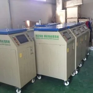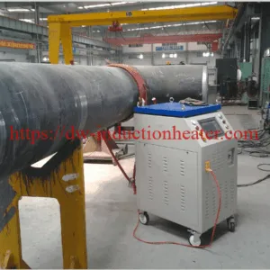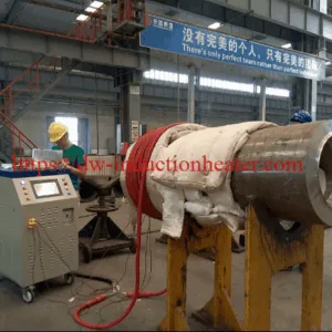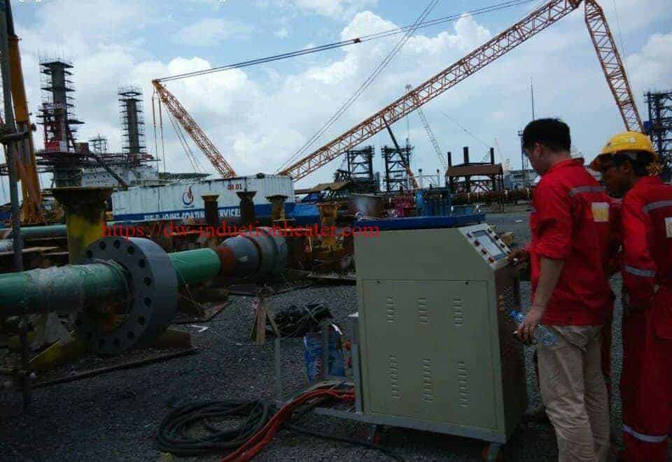




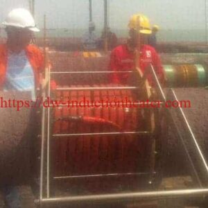

Induction pipeline coating machine
Induction Pipeline Coating Heating – Field-Joint Coating Preheat (FBE, 3LPE/3LPP, heat-shrink sleeves, liquid)
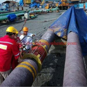
An induction pipeline coating machine heats a conductive steel pipe before a coating operation. The HLQ MYD range lists six models from 40 to 120 kW, with a published frequency range of 2-30 kHz. For field joint coating, the heater brings the exposed steel band to the temperature required by the coating procedure. Coil geometry, pipe wall thickness, heated width and available heating time determine the configuration. Coating application equipment is specified separately.
What is the Induction Pipeline Coating Machine?
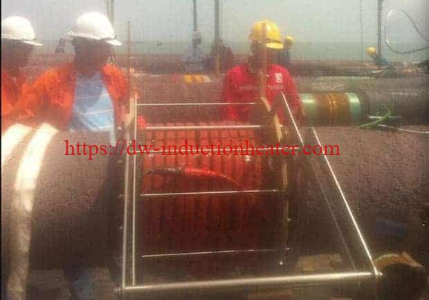
The HLQ MYD induction pipeline coating machine is a configurable heating package for the thermal stage of pipe coating preparation. A power converter, a suitable induction coil and temperature feedback work together to heat the steel substrate over a defined band.
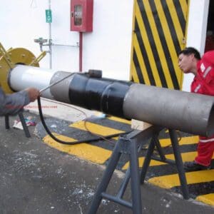
A project configuration may include an opening clamp coil or a flexible cable coil, thermocouples, connection leads, insulation and a temperature recorder. Spray heads, powder delivery, wrapping mechanisms and coating inspection equipment require their own defined scope. Preheating, coating cure and post-weld heat treatment each require an appropriate thermal procedure.

Key Applications
| Application | Heating objective | Required process definition |
|---|---|---|
| Pipeline field joint coating | Heat the exposed steel around a welded joint before coating application. | Cutback width, temperature distribution, adjacent-coating limit and permitted application delay. |
| Fusion-bonded epoxy preparation | Raise the substrate to the specified FBE application window. | Coating supplier’s temperature, gel and cure requirements; application equipment supplied separately. |
| Heat-shrink sleeve preparation | Preheat the steel and primer system as required by the sleeve procedure. | Approved primer, preheat temperature, sleeve installation and overlap requirements. |
| Local coating repair | Apply controlled heat to a defined repair area. | Remaining-coating tolerance, repair boundaries and inspection method. |
| Workshop coating preparation | Repeat a controlled thermal stage on similar pipe sections. | Fixture layout, handling time, sensor locations and documented acceptance criteria. |
Projects that also require weld preparation can evaluate the related induction welding preheat machine under the applicable welding procedure.

Suitable Materials
Material suitability starts with the pipe substrate. Induction heats an electrically conductive workpiece; a coating on that workpiece is heated through thermal transfer from the steel.
| Material or system | Assessment | Engineering consideration |
|---|---|---|
| Carbon steel pipe | Primary evaluation candidate. | Confirm grade, diameter, wall thickness, cutback width and target heating time. |
| Low-alloy steel pipe | Evaluate against its thermal and coating requirements. | Respect material-specific temperature limits and any applicable welding restrictions. |
| Stainless steel or other conductive alloys | Application trial required. | Verify electromagnetic coupling, coil design and achievable heating performance. |
| FBE, epoxy primers and heat-shrink systems | Potential coating processes supported by substrate heating. | Use the coating supplier’s approved application and cure procedure. |
| Plastic-only pipe | Direct suitability is not established for this package. | A separate conductive heating method or engineered arrangement would be needed. |
Working Principle
- Power conversion: the converter supplies controlled alternating current to the induction coil.
- Electromagnetic coupling: the coil produces a changing magnetic field around the conductive pipe.
- Heat generation: induced currents produce electrical resistance heating inside the steel.
- Heat distribution: conduction spreads heat through the pipe wall and into adjacent material.
- Feedback control: temperature sensors guide the heating cycle and support process records.

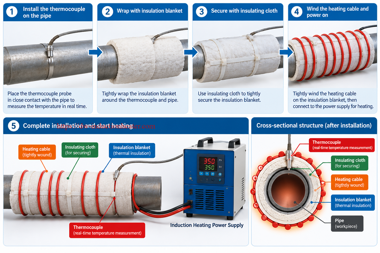
The induction heating principle explains why coil geometry, frequency, material properties and spacing affect the delivered heat. The coating temperature must be checked across the required surface area, including locations most likely to run hot or cold.

Technical Specifications
The following values reproduce the existing product listing. Shared ratings and accessories require confirmation in the selected model’s final datasheet.
| Model | Listed output power | Listed input current* |
|---|---|---|
| MYD-40KW | 40 kW | 60 A |
| MYD-50KW | 50 kW | 75 A |
| MYD-60KW | 60 kW | 90 A |
| MYD-80KW | 80 kW | 120 A |
| MYD-100KW | 100 kW | 150 A |
| MYD-120KW | 120 kW | 180 A |
*The voltage basis and rating method for these input-current figures are unspecified. Confirm actual input demand, power factor, efficiency, cable requirements and protective devices from the final electrical documentation.
| Parameter | Source-listed information | Selection note |
|---|---|---|
| Electrical supply | Three-phase 380 V AC default; 220 V and 440 V AC options; 50/60 Hz listed in the body. | Specify the site supply and exact ordered voltage. |
| Output frequency | 2-30 kHz. | Operating frequency depends on the coil and connected load. |
| Workpiece diameter | 100-1,500 mm listed. | A matching coil and sufficient heating power are required for each pipe geometry. |
| Maximum temperature claim | Up to 900°C. | Equipment capability claim; coating setpoints come from the coating procedure. |
| Heating-rate claim | 5-400°C/min. | Depends on heated mass, coil coupling, power and heat losses. |
| Control and sensors | DSP control; K-type thermocouples; six-channel control/recording listed. | Confirm sensor inputs, independent power outputs and recording functions separately. |
| Cooling | Air cooling listed; another source-page table refers to water cooling at 100 kW and above. | Confirm converter cooling and coil cooling for the selected duty. |
| Reference cabinet dimensions | 800 × 560 × 1,350 mm. | Source reference only; model-specific dimensions are unconfirmed. |
| Reference packing dimensions | 900 × 660 × 1,560 mm. | Verify the shipment configuration. |
| Reference weights | 120 kg net; 155-260 kg gross with parts. | The listing does not reliably allocate these weights to each model. |
| Listed accessories | Clamp or cable coil, connection leads, insulation, thermocouples and recorder. | Recorder names appear as R-1006 and ER-1006; confirm the supplied model and included items. |
Recommended Model Selection
Estimate the required thermal load first, then evaluate the next suitable power class with an agreed design allowance. A diameter-only selection chart cannot account for wall thickness, heated width, target temperature and production timing.
| Candidate model | Listed output | Calculated heating time* |
|---|---|---|
| MYD-40KW | 40 kW | 167 seconds |
| MYD-50KW | 50 kW | 134 seconds |
| MYD-60KW | 60 kW | 111 seconds |
| MYD-80KW | 80 kW | 83 seconds |
| MYD-100KW | 100 kW | 67 seconds |
| MYD-120KW | 120 kW | 56 seconds |
*Calculated for a 508 mm outside-diameter steel pipe, 12.7 mm wall and 300 mm heated band, raised from 25°C to an assumed 230°C. Assumptions: density 7,850 kg/m³, average heat capacity 0.490 kJ/(kg·K), and 70% effective output-to-steel heating factor. Times exclude handling, equalization, soak, coating and inspection. They are estimates rather than measured machine performance.
Evaluate flexible cable induction coils for adaptable layouts. For repeated pipe sizes, compare suitable induction heating coils against access, positioning time, band width and cooling requirements.
Process Workflow
| Stage | Action | Acceptance check |
|---|---|---|
| 1. Define the recipe | Establish the coating, thermal window and time allowance. | Use the approved coating data sheet and project procedure. |
| 2. Prepare the surface | Clean and blast the pipe as specified. | Verify cleanliness, surface profile and dew-point conditions. |
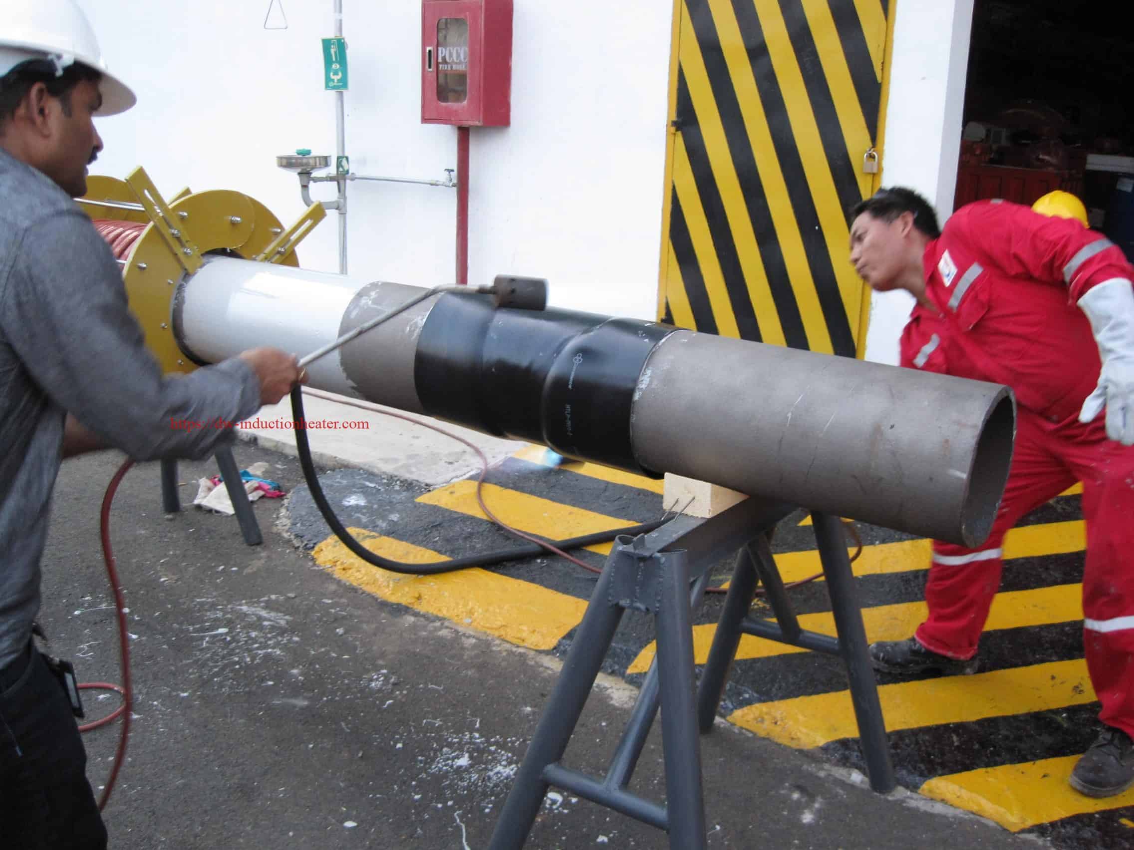
| 3. Fit coil and sensors | Set coil clearance and attach temperature sensors. | Check repeatable positioning and protect adjacent coating. |
| 4. Run the heating cycle | Apply the approved ramp or controlled heating step. | Check the complete required band for hot and cold locations. |
| 5. Apply the coating | Open or remove the coil and complete the coating operation as needed. | Remain inside the application-temperature and timing limits. |
| 6. Inspect and record | Complete cure/cooling and coating-specific inspection. | Retain temperature curves and required quality records. |
Common Problems and Solutions
| Problem | Possible cause | Recommended check |
|---|---|---|
| Uneven surface temperature | Variable coil spacing, asymmetric geometry or heat loss. | Adjust positioning and map temperatures around and along the band. |
| Heating takes too long | High thermal mass, poor coupling or insufficient delivered power. | Recalculate the load; check supply under load and coil matching. |
| Adjacent coating overheats | The effective heating zone extends beyond the cutback. | Revise coil width and the thermal protection plan. |
| Temperature readings fluctuate | Unstable sensor contact, cable damage or electrical interference. | Inspect attachment, compensation cable and signal routing. |
| Coating adhesion is weak | Contamination, moisture, incorrect profile or application temperature. | Review the entire coating procedure, including timing and surface preparation. |
| Cooling or overtemperature alarm | Restricted airflow, cooling-circuit fault or unsuitable duty. | Inspect the configured cooling system and confirm permitted operating duty. |
Where the approved heating arrangement requires insulation, evaluate suitable PWHT insulation blankets for temperature rating, placement and sensor access.
Engineering Selection Guide
Estimate the heated steel mass and thermal demand
For a pipe band with outside diameter D, wall thickness t and heated width L, use consistent SI units. With density ρ, average heat capacity cp, temperature rise ΔT and heating time τ:
Q = m × cp × ΔT
Poutput = Q / (ηeffective × τ)
Using metres, kg/m³, kJ/(kg·K) and seconds gives Q in kJ and output power in kW. For the example in the model table, the heated mass is approximately 46.54 kg and sensible heat is 4,675 kJ. A 90-second heating allowance at the assumed 70% effective factor requires approximately 74.2 kW. Applying an illustrative 20% design allowance gives 89.0 kW, making MYD-100KW a candidate for evaluation.
The assumed 230°C target is a calculation input, not a universal coating setpoint. The effective factor represents simplified coupling and heat retention; it is separate from converter electrical efficiency. Actual trials must account for adjoining pipe, conduction, wind, insulation and any required soak.
Confirm the complete operating conditions
- Workpiece: material grade, OD, wall thickness, heated width, pipe contents and parent coating.
- Process: coating system, permitted temperature band, application delay and total cycle target.
- Utilities: supply voltage/frequency, available kVA, cooling resources and ambient conditions.
- Controls: sensor positions, independent power outputs, recipe requirements and data records.
- Acceptance: temperature mapping, repeatability and coating-specific inspection criteria.
Where a project includes a separate heat-treatment stage, assess the appropriate induction PWHT system against that stage’s procedure and equipment requirements.
Advantages and Limitations
| Potential advantage | Practical value | Limitation or validation need |
|---|---|---|
| Localized heat generation | Direct heating of the conductive steel in the coil zone. | Coil design and thermal conduction determine the actual heated area. |
| Heating without a burner flame | Removes a combustion flame from the heating step. | Hot surfaces, electrical systems and site conditions still require appropriate controls. |
| Repeatable heating recipes | Supports consistent setup and temperature control. | Repeatability depends on workpiece consistency, sensors and validated positioning. |
| Temperature records | Supports process traceability when the recorder is included. | Channel count, storage, export and supplied recorder model must be confirmed. |
| Different coil arrangements | Allows evaluation of repeated or variable pipe geometries. | One coil cannot be assumed to cover every diameter, heating width and duty. |
| Potentially shorter thermal stages | Power can be selected around the heated mass and timing target. | Production throughput and energy savings require measured project data. |
Why Choose HLQ?
HLQ’s published MYD offering provides a practical starting point for matching an induction power supply, coil and temperature-control arrangement to a pipeline heating task.
- Six listed power classes: 40, 50, 60, 80, 100 and 120 kW for preliminary load-based screening.
- Coil options: opening clamp and flexible cable arrangements to evaluate against access and geometry.
- Process components: temperature sensing, recording, connection leads and insulation are identified in the source listing.
- Engineering inputs: selection can be based on material, dimensions, thermal window, timing and available utilities.
The final package should identify the ordered model, electrical ratings, converter and coil cooling, included accessories, sensor configuration and acceptance criteria in one consistent technical document.
10 Core FAQs
1. What does an induction pipeline coating machine do?
It heats the conductive steel substrate during coating preparation. The MYD package is evaluated as the heating stage; coating application equipment has a separate defined scope.
2. Which MYD models are listed for this product?
The original model table lists MYD-40KW, MYD-50KW, MYD-60KW, MYD-80KW, MYD-100KW and MYD-120KW.
3. Can it support FBE field joint coating?
It can be evaluated for steel preheating before FBE application. Temperature, application timing, gel and cure requirements must follow the coating supplier’s procedure and project qualification.
4. Is it suitable for heat-shrink sleeve preparation?
Induction heating can provide substrate preheat for an approved sleeve procedure. The primer, target temperature, application sequence and installation checks must be defined for the selected sleeve.
5. Does the 100-1,500 mm diameter listing guarantee every pipe size?
No. Coil dimensions, wall thickness, heated width, access and heating time determine suitability. The published diameter range is a preliminary reference.
6. Are all six models fully air cooled?
The source page contains conflicting cooling descriptions. Confirm converter cooling and coil cooling separately for the selected power, temperature and operating duty.
7. Does the listed 900°C maximum describe the coating setpoint?
No. It is a source-listed equipment capability claim. The permitted coating temperature comes from the approved coating procedure.
8. Do six channels mean six independent heating zones?
The source does not establish that relationship. Verify the number of temperature inputs, independently controlled power outputs and recorder channels.
9. How should the power rating and heating time be selected?
Estimate heated mass and temperature rise, divide the heat requirement by the available heating time and effective heating factor, then apply an agreed design allowance. Validate the candidate system on the actual workpiece.
10. Can the same MYD system perform PWHT?
The MYD series is also marketed for PWHT. Its suitability for a particular heat-treatment procedure depends on power, coil and insulation ratings, sensor arrangement, cooling and the required temperature cycle.