

Induction Heating Equipment
DW-HF-160 High Frequency Induction Heating Equipment for Industrial Heat Treatment
Quick Answer
What is the DW-HF-160 High Frequency Induction Heating Equipment?
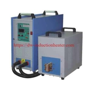
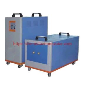
The HLQ DW-HF-160KW is an industrial high-frequency induction heating system designed for localized metal heating, surface hardening, brazing, annealing, shrink fitting, and selected forging preheating applications. According to the original manufacturer-published specifications, the machine has a maximum input power rating of 160kW, an output oscillation-frequency range of 20–80kHz, and a three-phase 380V, 50/60Hz electrical supply. It uses an IGBT induction generator, a separate high-frequency transformer, an application-specific induction coil, and a water-cooling system.
Best-Fit Applications: Gear and shaft surface hardening, industrial diamond and carbide tool brazing, electric kettle bottom brazing, steel tube heating, stainless steel component annealing, localized metal preheating, shrink fitting, and selected metal-forming operations.
Engineering Selection: The appropriate induction heating equipment must be selected according to material grade, workpiece dimensions, effective heated mass, target temperature, required heating depth, heating time, production rate, induction coil geometry, and available electrical and cooling utilities. The published maximum input power of 160kW does not establish a guaranteed 160kW useful thermal output at the workpiece.
Table of Contents
- What Is the DW-HF-160 High Frequency Induction Heating Equipment?
- Key Applications
- Suitable Materials
- Working Principle
- Technical Specifications
- Recommended Model Selection
- Process Workflow
- Common Problems and Solutions
- Engineering Selection Guide
- Advantages and Limitations
- Why Choose HLQ?
- 10 Core FAQs
What Is the DW-HF-160 High Frequency Induction Heating Equipment?
The DW-HF-160 High Frequency Induction Heating Equipment is an industrial electromagnetic heating system that uses high-frequency alternating current to generate heat within electrically conductive metal components.
The machine converts three-phase electrical input into controlled high-frequency electrical energy. This energy is delivered through a matching circuit and high-frequency transformer to a water-cooled induction coil.
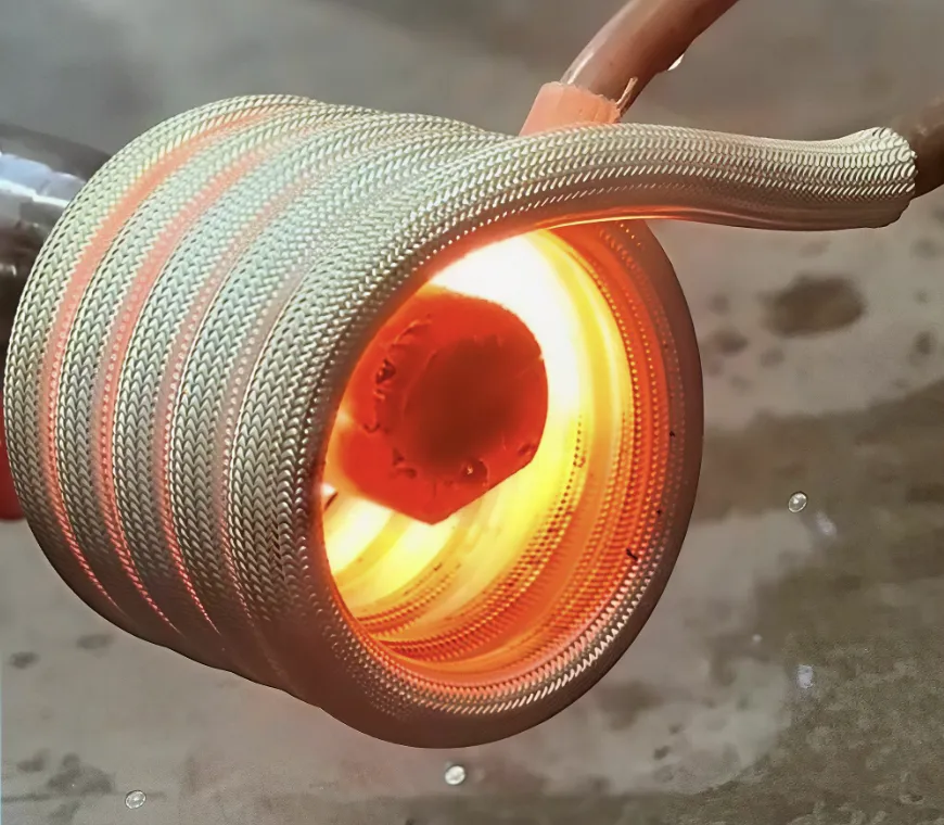
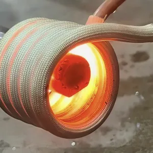
The alternating current flowing through the induction coil generates a changing magnetic field. When a conductive metal workpiece is positioned within this field, electrical currents are induced inside the material.
The electrical resistance of the metal converts the induced currents into heat. Depending on the induction frequency, material properties, coil geometry, and heating duration, the resulting heat can be concentrated near the surface or distributed further into the component through thermal conduction.
The equipment can be configured for different industrial applications through appropriate induction coils, workpiece fixtures, temperature-monitoring equipment, and production controls.
Unlike a complete automated induction hardening machine, the induction power supply alone does not necessarily include a CNC scanner, quenching station, robotic handling system, or closed-loop temperature controller. Such components must be specified separately when required by the manufacturing process.
Main Components of the DW-HF-160 Induction Heating System
| Component | Function | Engineering Requirement |
|---|---|---|
| IGBT Induction Generator | Converts incoming industrial electricity into controlled high-frequency power | Compatible electrical supply, rated load, grounding, and protection |
| High-Frequency Transformer | Matches the electrical output to the induction heating circuit | Compatible current, voltage, impedance, and operating frequency |
| Resonant Matching Circuit | Supports electrical matching between the inverter and induction load | Correct capacitance, inductance, and load characteristics |
| Water-Cooled Induction Coil | Generates the alternating magnetic field around the workpiece | Appropriate geometry, clearance, current capacity, and cooling |
| Heating Controller | Regulates selected operating parameters and heating cycles | Verify constant-current and timer functions |
| Workpiece Fixture | Positions and supports the metal component | Mechanical stability and repeatable alignment |
| Cooling System | Removes heat from the coil and designated electrical components | Verified water flow, pressure, temperature, and water quality |
| Protection System | Responds to specified electrical and cooling abnormalities | Approved protection settings and safe shutdown functions |
| Optional Automation | Coordinates workpiece positioning, scanning, and process control | Defined separately for the complete production installation |

Split-Type Induction Heating Equipment
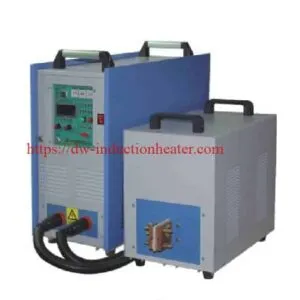
The DW-HF-160 uses a separated generator and high-frequency transformer arrangement.
The generator contains the main electrical power-conversion equipment, while the transformer and induction coil can be positioned closer to the workpiece heating station.
This arrangement can provide greater installation flexibility in industrial production environments.
However, the electrical connections, transformer location, cable length, cooling circuit, and mechanical clearances must remain within the approved system configuration.
| Feature | Potential Benefit | Engineering Consideration |
|---|---|---|
| Separate Generator | Allows placement away from the immediate workpiece heating zone | Ventilation, electrical access, grounding, and cabinet protection |
| Separate HF Transformer | Allows the heating head to be positioned near production equipment | Mechanical support, electrical connections, and cooling |
| Interconnecting Cable | Provides installation flexibility | Manufacturer-approved cable length and electrical matching |
| Application-Specific Coil | Allows heating of different compatible workpiece geometries | Coil design and electrical load matching |
| Production-Line Installation | Can support integration with fixtures and handling systems | Define control interfaces and equipment safety requirements |
Key Applications
The DW-HF-160 can be evaluated for industrial metal-heating processes where controlled electromagnetic heating is required.
The correct heating configuration depends on the workpiece dimensions, material properties, required temperature distribution, production capacity, and operating frequency.
1. Induction Surface Hardening of Gears and Shafts
Induction surface hardening is used to improve the wear resistance of suitable steel components.
The induction coil heats a selected surface region to the required austenitizing temperature. The heated material is then quenched according to the approved metallurgical process.
Typical components include shafts, gears, splines, pins, rollers, sprockets, and selected automotive parts.
Depending on the component geometry, the complete system may require an encircling coil, scanning mechanism, workpiece rotation, quenching equipment, and process controller.
The final hardness and hardened case depth depend on steel grade, temperature, heating duration, operating frequency, quenching conditions, and part geometry.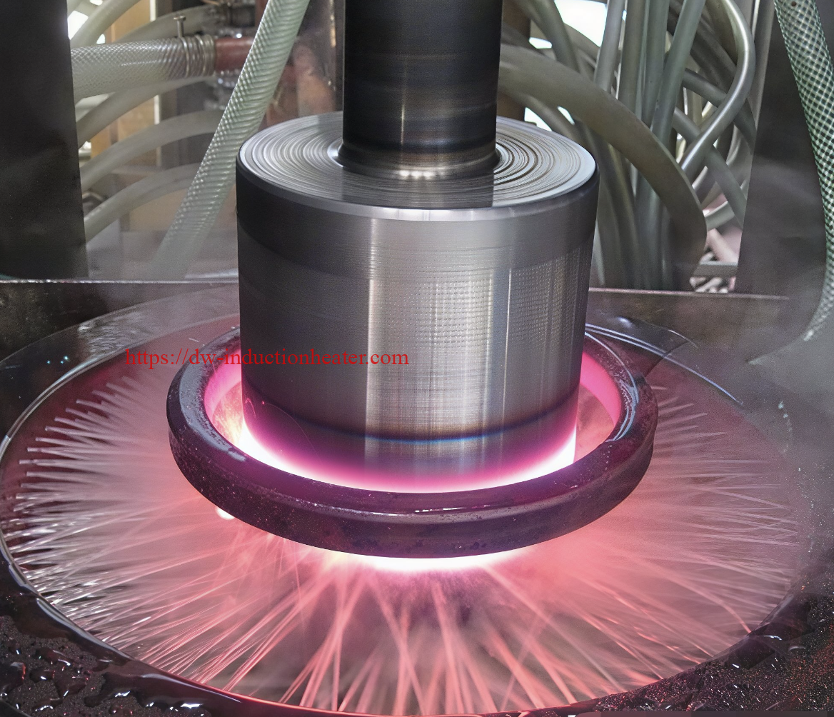
For a complete heat-treatment workstation, compare HLQ’s induction hardening machine configurations.
2. Brazing of Diamond and Carbide Tools
Induction heating can be used to join suitable diamond-tool segments and carbide cutting tips to compatible metal bodies using qualified brazing filler metals.
The induction coil should concentrate heating at the joining interface while controlling thermal gradients and preventing damage to the cutting component.
Filler-metal compatibility, joint clearance, flux requirements, heating temperature, and cooling conditions must be evaluated for each application.
3. Electric Kettle Bottom Brazing
Induction heating can be used in selected cookware and electric-kettle manufacturing processes that require brazing of metallic components.
The actual heating arrangement depends on the kettle-bottom geometry, materials, filler metal, and required production rate.
A flat, pancake, or application-specific induction coil may be considered according to the assembly design.
4. Stainless Steel Vessel Annealing
Stainless steel vessels and components may require localized heating or annealing during fabrication or manufacturing.
Different stainless steel grades have different heat-treatment requirements.
The induction system must be designed according to vessel geometry, material grade, required temperature, heating zone, and process duration.
5. Steel Tube Heating for Coating Applications
Induction heating may be used to heat steel tubes before selected coating, bonding, or thermal-processing operations.
The heating system should provide an appropriate surface temperature without exceeding the limits of the workpiece or subsequent coating process.
For continuous tube heating, production speed, tube diameter, wall thickness, and heated length are important engineering variables.
6. Copper and Brass Tube Brazing
Induction brazing can be used to join suitable copper tubes, brass connectors, valves, and industrial fittings.
The joint should be heated to the required brazing temperature so that the selected filler metal can melt, wet the surfaces, and flow through the joint.
Since copper and brass have different electrical and thermal properties from carbon steel, coil design and power matching must be evaluated separately.
For different joint configurations, review HLQ’s industrial induction brazing machine solutions.
7. Induction Heating of Rods Before Forging
Induction heating can be used to preheat metal rods and selected forging regions before upsetting, heading, pressing, and hot forming.
However, the high-frequency DW-HF-160 should not automatically be selected for every large-diameter billet or through-heating application.
The operating frequency must be matched to the workpiece diameter and required temperature profile.
8. Metal Shrink Fitting and Thermal Assembly
Induction heating can expand gears, rings, sleeves, and other metal components before assembly onto a shaft or mating component.
The required heating temperature depends on the interference allowance, thermal expansion coefficient, and dimensional tolerances.
| Application | Material | Heating Objective | Engineering Requirement |
|---|---|---|---|
| Gear Surface Hardening | Carbon and alloy steel | Localized austenitizing before quenching | Correct hardening pattern and case depth |
| Shaft Surface Hardening | Suitable steel grades | Heat selected shaft surfaces | Coil movement, rotation, and quenching |
| Diamond Tool Brazing | Tool steel and compatible cutting segments | Heat the brazing interface | Filler compatibility and thermal stress control |
| Carbide Tool Brazing | Steel and carbide | Join cutting inserts to holders | Controlled interface temperature |
| Kettle Bottom Brazing | Application-specific metal assembly | Heat the joining interface | Planar heating and filler distribution |
| Stainless Steel Vessel Heating | Stainless steel | Localized annealing or process heating | Grade-specific thermal requirements |
| Steel Tube Heating | Carbon and alloy steel | Preheat for selected coating processes | Controlled temperature and line speed |
| Copper and Brass Brazing | Copper and brass | Heat the joint for filler flow | Joint geometry and coil coupling |
| Rod Forging Preheating | Steel and selected alloys | Prepare the metal for forming | Core temperature and frequency selection |
| Shrink Fitting | Steel rings and sleeves | Produce controlled thermal expansion | Expansion allowance and temperature limits |
Suitable Materials
Induction heating can be applied to electrically conductive materials, including ferromagnetic and nonferromagnetic metals.
The resulting heating performance depends on the material’s electrical resistivity, magnetic permeability, thermal conductivity, specific heat capacity, workpiece geometry, and operating temperature.
| Material | Heating Characteristics | Potential Application | Engineering Consideration |
|---|---|---|---|
| Carbon Steel | Magnetic properties change significantly during heating | Hardening, preheating, thermal assembly | Account for the Curie transition and required heating depth |
| Alloy Steel | Properties depend on alloy composition | Gear and shaft heat treatment | Use grade-specific temperature and quenching requirements |
| Stainless Steel | Magnetic and electrical characteristics vary by grade | Annealing and localized heating | Confirm the actual alloy specification |
| Copper | High electrical and thermal conductivity | Brazing and electrical connections | Optimize coil coupling and heating time |
| Brass | Conductive copper-zinc alloy | Valve and fitting brazing | Control temperature and zinc-related process risks |
| Aluminum Alloys | Nonferromagnetic and highly conductive | Selected local heating and assembly | Use alloy-specific temperature limits |
| Nickel Alloys | Properties vary according to composition | Specialized joining and thermal processing | Verify material-specific heating conditions |
| Carbide-Steel Assemblies | Components have different thermal expansion characteristics | Industrial tool brazing | Control filler-metal compatibility and thermal stress |
Material Properties Affecting Induction Heating Performance
| Property | Effect on Heating | Engineering Requirement |
|---|---|---|
| Electrical Resistivity | Influences resistive losses caused by induced currents | Use appropriate temperature-dependent material values |
| Magnetic Permeability | Changes induced current distribution | Consider magnetic transitions in steel |
| Thermal Conductivity | Influences heat distribution within the component | Evaluate surface and core temperature requirements |
| Specific Heat Capacity | Influences the energy required to heat the material | Use suitable values across the temperature range |
| Metallurgical Transformations | May change required heat input and material condition | Include process-specific requirements |
| Workpiece Geometry | Influences electromagnetic coupling and effective heated mass | Use actual part dimensions |
| Initial Temperature | Changes the required temperature increase | Specify the starting temperature |
| Target Temperature | Determines thermal demand and processing limits | Use application-specific temperature requirements |
Working Principle
The DW-HF-160 works according to electromagnetic induction.
Incoming three-phase electrical power is converted by an IGBT inverter into high-frequency alternating current.
The current is transferred through the appropriate matching and transformer arrangement to the induction coil.
When high-frequency alternating current flows through the copper induction coil, it generates a changing magnetic field.
When a conductive metal workpiece is positioned within this field, electrical currents are induced inside the workpiece.
The electrical resistance of the workpiece converts the induced currents into heat.
For ferromagnetic steels, temperature-dependent magnetic behavior must also be considered. Above the Curie region, the material’s magnetic permeability changes significantly.
Electromagnetic Induction Heating Sequence
| Step | Component | Function |
|---|---|---|
| 1 | Three-Phase Power Supply | Provides industrial electrical input |
| 2 | IGBT Induction Generator | Produces controlled high-frequency electrical power |
| 3 | HF Transformer and Matching Circuit | Matches the output to the induction heating load |
| 4 | Water-Cooled Copper Coil | Generates an alternating magnetic field |
| 5 | Conductive Workpiece | Absorbs electromagnetic energy and generates heat |
| 6 | Thermal Conduction | Redistributes heat within the metal |
| 7 | Process Control | Controls the selected heating sequence |
| 8 | Application-Specific Operation | Completes hardening, brazing, annealing, or forming preparation |
Operating Frequency and Electrical Skin Depth
The manufacturer publishes a high-frequency operating range of 20–80kHz for the DW-HF-160.
The actual operating frequency depends on the induction coil, resonant matching, and workpiece characteristics.
For a homogeneous material under simplified electromagnetic conditions, reference electrical skin depth can be estimated using:
δ = √[ρ / (π × f × μ)]
Where:
- δ = Electrical skin depth, m.
- ρ = Electrical resistivity, Ω·m.
- f = Operating frequency, Hz.
- μ = Absolute magnetic permeability, H/m.
The electrical skin depth is not identical to the final heating depth or hardened case depth.
The final temperature distribution also depends on heating duration, thermal conduction, material geometry, and temperature-dependent material properties.
Theoretical Copper Skin Depth at Different Frequencies
The following values are calculated using an electrical resistivity of approximately 1.72 × 10⁻⁸ Ω·m and a relative magnetic permeability of approximately 1 at room temperature.
| Frequency | Approximate Skin Depth | Engineering Interpretation |
|---|---|---|
| 20kHz | 0.467mm | Lower-frequency end of the published DW-HF-160 range |
| 30kHz | 0.382mm | Intermediate reference frequency |
| 40kHz | 0.330mm | Intermediate reference frequency |
| 60kHz | 0.269mm | Higher-frequency reference |
| 80kHz | 0.233mm | Upper end of the published frequency range |
Engineering Note: These values describe theoretical electrical current penetration in copper near room temperature, not actual measured workpiece temperatures or a guarantee of heating depth.
Induction Coil Design
The induction coil is a critical component of the heating system.
Its shape, number of turns, conductor size, active heating length, and distance from the workpiece influence magnetic coupling and temperature distribution.
Different industrial applications may require completely different induction coil designs.
| Application | Coil Type | Design Requirement |
|---|---|---|
| Gear Surface Hardening | Profile or scanning coil | Targeted surface heating |
| Shaft Hardening | Encircling or scanning coil | Defined heated length and quench integration |
| Diamond Tool Brazing | Pancake or custom-profile coil | Localized brazing-interface heating |
| Kettle Bottom Brazing | Flat or profile coil | Suitable planar heat distribution |
| Steel Tube Annealing | Helical or split coil | Circumferential heating and temperature control |
| Copper Tube Brazing | Helical or U-shaped coil | Uniform joint temperature |
| Rod Forging | Helical or specialized through-heating coil | Required core temperature and heating time |
| Shrink Fitting | Encircling or custom-profile coil | Controlled thermal expansion |
For detailed electromagnetic and mechanical design considerations, see HLQ’s custom induction heating coil design guide.
Technical Specifications
The following data preserves the manufacturer-published specifications of the DW-HF-160 induction heating equipment.
Where the published information is ambiguous, the required engineering verification is identified.
DW-HF-160 Published Technical Specifications
| Parameter | Published Specification | Engineering Notes |
|---|---|---|
| Model | DW-HF-160KW | Manufacturer-published model name |
| Equipment Category | High Frequency Induction Heating Equipment | Industrial localized heating and thermal processing |
| Nominal Input Voltage | 380V ±10%, Three Phase | Verify the acceptable full-load voltage range |
| Separately Published Input Voltage Range | 320–420V | Does not exactly match the ±10% tolerance |
| Input Frequency | 50/60Hz | Industrial supply frequency |
| Maximum Input Power | 160kW | Input power rating, not verified useful heating power |
| Duty Cycle | 100% | Verify rated load, ambient temperature, and cooling conditions |
| Output Control Mode | Constant Current Control | Confirm available control functions |
| Output Oscillation Frequency | 20–80kHz | Actual loaded frequency depends on the heating circuit |
| Resistance Matching | 1–4 selections or non-adjustable | Original wording requires technical clarification |
| Heating Oscillation Current | 100–1260A | HF-circuit current; measurement location must be confirmed |
| Retain Oscillation Current | 100–1260A | Published value for the retain stage |
| Heating Time | 0.1–99.9 seconds | Published timer range |
| Retain Time | 0.1–99.9 seconds | Published timer range |
| Generator Weight | 80kg | Published generator weight |
| HF Transformer Weight | 75kg | Published transformer weight |
| Generator Dimensions | 640 × 350 × 560mm | Dimension order should be verified |
| HF Transformer Dimensions | 820 × 350 × 460mm | Dimension order should be verified |
| Generator-to-Transformer Cable | 2m | Longer cables require electrical approval |
| Cooling Water Pressure | >0.2MPa | Confirm minimum pressure and maximum permissible pressure |
| Cooling Water Temperature | <40°C | Confirm measurement location and protection threshold |
| Cooling Water Flow | >100L/min | Confirm total-system versus individual-circuit requirement |
Important Electrical Specification Clarifications
| Parameter | Published Information | Required Clarification |
|---|---|---|
| Maximum Input Power | 160kW | Confirm the rated operating condition and measurement boundary |
| Input Voltage | 380V ±10% and 320–420V | Confirm the full-load permitted voltage range |
| Input Current | Not explicitly specified in the target table | Provide rated maximum supply-line current |
| Input Power Factor | Not explicitly specified | Provide supply-side power factor |
| Useful Thermal Output | Not specified | Verify through representative application testing |
| HF Oscillation Current | 100–1260A | Confirm measurement location and electrical definition |
| Operating Frequency | 20–80kHz | Confirm the frequency range under representative loads |
| Duty Cycle | 100% | Confirm operating load, temperature, and cooling conditions |
Three-Phase Electrical Supply Calculation
The relationship between three-phase active power, line voltage, line current, and power factor is:
P = √3 × Vline × Iline × PF
Where:
- P = Three-phase input active power, W.
- Vline = Line-to-line voltage, V.
- Iline = Line current, A.
- PF = Input power factor.
For illustration, assuming 160kW input power, 380V line voltage, and unity power factor, the theoretical current is approximately 243A.
If the assumed power factor is 0.90, the corresponding theoretical input current increases to approximately 270A.
These calculations are not actual DW-HF-160 input-current measurements. Electrical protection and cable sizing must use verified equipment data.
Cooling System Requirements
The DW-HF-160 is a water-cooled induction heating system.
The original product page publishes a cooling-water flow greater than 100L/min, a pressure greater than 0.2MPa, and a temperature below 40°C.
These values require additional confirmation before the cooling system is selected.
| Cooling Parameter | Published Value | Engineering Verification |
|---|---|---|
| Cooling Method | Water Cooling | Confirm the complete equipment cooling arrangement |
| Cooling Water Flow | >100L/min | Confirm whether total system flow or individual branch flow |
| Cooling Water Pressure | >0.2MPa | Confirm permitted pressure range and measurement point |
| Cooling Water Temperature | <40°C | Confirm inlet-temperature limit and sensor location |
| Cooling Water Quality | Not fully specified | Confirm conductivity, hardness, filtration, and corrosion limits |
| Cooling Connections | Model-specific | Verify the number and dimensions of water connections |
| Cooling Protection | Water-failure protection described | Confirm the flow sensor and shutdown response |
| Cooling Unit Capacity | Not specified | Determine from verified equipment heat rejection |
Illustrative Cooling Water Heat Removal
The theoretical heat carried by a cooling-water circuit can be estimated from:
P = mflow × Cp × ΔT
Assuming a water flow of 100L/min and a specific heat capacity of approximately 4.18kJ/kg·K:
| Water Flow | Water Temperature Rise | Theoretical Heat Removal |
|---|---|---|
| 100L/min | 2°C | 13.9kW |
| 100L/min | 4°C | 27.9kW |
| 100L/min | 5°C | 34.8kW |
| 100L/min | 6°C | 41.8kW |
| 100L/min | 8°C | 55.7kW |
| 100L/min | 10°C | 69.7kW |
Engineering Qualification: These values are theoretical water-side heat-transfer calculations. They do not represent measured DW-HF-160 electrical losses or establish the required chiller cooling capacity.
Recommended Model Selection
The correct induction heating machine must be selected according to the workpiece and heating process.
Maximum input power alone does not determine maximum workpiece size, production capacity, hardening depth, or heating time.
Application-Based Equipment Selection
| Application | Equipment Class to Evaluate | Frequency Consideration | Selection Requirement |
|---|---|---|---|
| Small Local Brazing | Lower-power HF or UHF equipment | Matched to joint size | Filler metal and joint temperature |
| Medium Industrial Brazing | DW-HF-45 / DW-HF-60 or suitable alternative | Application-specific | Workpiece mass and heating time |
| Gear Surface Hardening | DW-HF-120 / DW-HF-160 candidates | Matched to required hardening pattern | Material, case depth, and quenching |
| Shaft Surface Hardening | DW-HF-120 / DW-HF-160 candidates | Load-dependent | Workpiece diameter, heated length, and quench cycle |
| Industrial Tool Brazing | DW-HF-160 or lower-power compatible system | Joint-specific | Coil geometry and thermal stress |
| Steel Tube Heating | DW-HF-160 candidate | Depends on wall thickness and heating objective | Tube temperature and production speed |
| Rod Forging Preheating | HF or MF system after engineering evaluation | Deeper heating may require lower frequency | Core temperature and mass throughput |
| Large Billet Through-Heating | Medium-frequency induction furnace | Generally lower frequency than localized HF heating | Cross-sectional temperature uniformity |
| Industrial Metal Melting | Dedicated induction melting furnace | Selected for charge material and furnace design | Melting capacity and thermal efficiency |
DW-HF-160 vs. DW-MF-160
The DW-HF-160 and DW-MF-160 are different equipment families.
They should not be selected solely because both model names contain the number 160.
| Comparison | DW-HF-160 | DW-MF-160 |
|---|---|---|
| Equipment Series | High Frequency | Medium Frequency |
| Published DW-HF-160 Frequency | 20–80kHz | Different MF operating range |
| Typical Heating Objective | Selected localized and surface-heating applications | Selected deeper and larger-section heating applications |
| Electrical Configuration | DW-HF-specific inverter and transformer arrangement | DW-MF-specific power supply and resonant arrangement |
| Coil Design | Application-specific HF coil | Application-specific MF coil |
| Selection Basis | Material, heating pattern, cycle, and electrical matching | Material, heating depth, throughput, and electrical matching |
For large billets, bars, and rods requiring through-heating, compare HLQ’s induction forging bar and billet furnace solutions.
Process Workflow
A reliable industrial induction heating process requires coordinated material preparation, coil selection, cooling verification, electrical inspection, workpiece positioning, heating control, and quality inspection.
General DW-HF-160 Heating Process
| Step | Operation | Engineering Objective |
|---|---|---|
| 1 | Material Identification | Confirm workpiece grade and dimensions |
| 2 | Process Definition | Specify the required temperature and heating pattern |
| 3 | Induction Coil Selection | Match the coil to the workpiece and generator |
| 4 | Cooling System Inspection | Verify approved water flow and temperature |
| 5 | Electrical Inspection | Verify supply, grounding, connections, and protection |
| 6 | Workpiece Positioning | Maintain the required coil-to-workpiece relationship |
| 7 | Induction Heating | Apply the selected heating cycle |
| 8 | Temperature Verification | Confirm the required process temperature |
| 9 | Application-Specific Processing | Perform quenching, brazing, annealing, or forming as required |
| 10 | Quality Inspection | Verify the required product characteristics |
Induction Hardening Process
For surface hardening, suitable steel components are heated to the required austenitizing condition and then quenched according to the approved heat-treatment procedure.
The complete system may require an induction coil, scanning mechanism, workpiece rotation, quenching system, and temperature-monitoring equipment.
| Process Parameter | Function | Quality Requirement |
|---|---|---|
| Material Grade | Determines hardenability | Approved steel composition and initial condition |
| Heating Temperature | Produces the required austenitized zone | Grade-specific process limits |
| Heating Duration | Influences thermal penetration | Required surface and core temperature relationship |
| Induction Frequency | Influences induced-current distribution | Matched to the desired heating pattern |
| Coil Position | Controls the effective heating zone | Repeatable fixture alignment |
| Quench Delay | Coordinates heating and cooling | Approved process timing |
| Quench Medium | Provides the required cooling behavior | Suitable temperature, flow, and concentration |
| Hardness Inspection | Verifies the metallurgical result | Specified hardness and hardened case depth |
Induction Brazing Process
For brazing, the selected filler metal must be compatible with the base materials and intended service conditions.
The workpiece surfaces are cleaned and assembled with the required joint clearance.
The induction coil heats the joint to the specified brazing temperature without intentionally melting the base materials.
The filler metal melts, wets the joining surfaces, and flows into the joint before solidifying during cooling.
Induction Tube Heating Process
For tube heating applications, the induction coil can be designed around a stationary tube or integrated into a suitable continuous processing line.
Tube outer diameter, wall thickness, line speed, material grade, and required temperature must be specified before selecting the power supply and coil.

Common Problems and Solutions
The performance of an industrial induction heating system depends on electrical matching, induction coil design, workpiece positioning, cooling conditions, and the selected heating cycle.
| Problem | Possible Cause | Recommended Solution |
|---|---|---|
| Slow Workpiece Heating | Insufficient useful power, poor coupling, or excessive heated mass | Verify loaded electrical conditions, coil geometry, and heating requirements |
| Uneven Heating | Incorrect induction coil geometry or workpiece positioning | Review magnetic-field distribution and fixture alignment |
| Surface Overheating | Excessive local power density or insufficient temperature equalization time | Review power, frequency, coil geometry, and heating duration |
| Insufficient Core Temperature | Insufficient heating time or unsuitable operating frequency | Validate internal temperature and consider alternative heating arrangements |
| Inconsistent Hardness | Variation in temperature or quenching conditions | Improve heating and quenching repeatability |
| Hardening Cracks | Excessive thermal gradients or unsuitable quench severity | Review steel grade, heating cycle, and quench process |
| Poor Brazing Filler Flow | Unsuitable filler metal, surface contamination, or insufficient joint temperature | Verify filler compatibility, cleaning, and heating conditions |
| Cooling Water Alarm | Insufficient flow, blockage, or high coolant temperature | Stop heating and inspect the cooling circuit |
| Excessive Cooling Pressure | Incorrect pump selection or restricted cooling connections | Verify the permitted pressure range and circuit restrictions |
| Overcurrent Alarm | Electrical mismatch or equipment fault | Isolate equipment and arrange qualified inspection |
| Unstable Oscillation Frequency | Changing workpiece load or resonant matching issue | Check coil compatibility and electrical matching |
| Coil Overheating | Insufficient cooling or excessive electrical losses | Inspect water circulation and coil condition |
| Frequent Shutdown | Cooling, electrical, or protection fault | Record fault information and investigate safely |
| Inconsistent Production Quality | Variable workpiece position, material, or process settings | Improve fixture repeatability and validate the process parameters |
Engineering Selection Guide
The correct induction heating machine must be selected from the workpiece and required thermal process rather than the equipment model name alone.
Step 1: Identify the Workpiece Material
Specify the exact metal grade and any relevant metallurgical requirements.
Different metals respond differently to induction heating because their electromagnetic and thermal properties vary.
Step 2: Determine the Workpiece Geometry
Provide dimensions, total weight, effective heated length, and the required heating zone.
The effective heated mass may be smaller than the entire workpiece mass when only a localized region is heated.
Step 3: Define the Required Temperature
Specify the initial temperature, target temperature, and acceptable temperature distribution.
For critical processes, distinguish between surface temperature and core temperature.
Step 4: Establish the Required Heating Cycle
Define the heating time, holding time if required, and production rate.
The actual cycle may be limited by workpiece handling, thermal diffusion, cooling, and downstream processing.
Step 5: Calculate the Effective Heated Mass
For a solid cylindrical component:
m = ρ × π × d² × L / 4
Where:
- m = Effective heated mass, kg.
- ρ = Material density, kg/m³.
- d = Cylinder diameter, m.
- L = Effective heated length, m.
Step 6: Estimate the Required Heating Energy
For a simplified sensible-heating calculation:
Q = m × Cp × ΔT
Where:
- Q = Useful theoretical thermal energy, kJ.
- m = Effective heated mass, kg.
- Cp = Approximate mean specific heat capacity, kJ/kg·K.
- ΔT = Temperature increase, K.
This simplified calculation excludes detailed temperature-dependent properties, phase-transformation effects, and system losses.
Engineering Calculation Example: AISI 1045 Steel Heating
Consider a hypothetical AISI 1045 steel cylindrical component with a diameter of 50mm and an effective heated length of 100mm.
Assume the material is heated from 25°C to 850°C.
For preliminary calculations, use a steel density of 7850kg/m³ and an approximate mean specific heat capacity of 0.62kJ/kg·K.
| Parameter | Value | Data Status |
|---|---|---|
| Material | AISI 1045 Steel | Illustrative example |
| Diameter | 50mm | Assumed |
| Heated Length | 100mm | Assumed |
| Density | 7850kg/m³ | Approximate reference |
| Effective Heated Mass | Approximately 1.541kg | Calculated |
| Initial Temperature | 25°C | Assumed |
| Target Temperature | 850°C | Assumed |
| Temperature Increase | 825K | Calculated |
| Mean Specific Heat | 0.62kJ/kg·K | Approximate assumption |
| Theoretical Heating Energy | Approximately 788kJ | Calculated |
| Equivalent Thermal Energy | Approximately 0.219kWh | Calculated |
Engineering Interpretation: The theoretical useful thermal energy required to raise this effective heated mass from 25°C to 850°C is approximately 788kJ.
The actual heating process will also involve electromagnetic losses, thermal losses, temperature-dependent material properties, and possible metallurgical transformations.
Step 7: Compare Heating Time and Power
For the same theoretical heating energy, average useful thermal power depends on heating duration.
The following table includes an illustrative electrical-input estimate using an assumed overall electrical-to-workpiece efficiency of 50%.
| Heating Time | Useful Thermal Power | Electrical Input at Assumed 50% Efficiency |
|---|---|---|
| 15 seconds | 52.6kW | 105.1kW |
| 20 seconds | 39.4kW | 78.8kW |
| 25 seconds | 31.5kW | 63.1kW |
| 30 seconds | 26.3kW | 52.6kW |
| 40 seconds | 19.7kW | 39.4kW |
| 60 seconds | 13.1kW | 26.3kW |
Engineering Qualification: These are theoretical calculations, not measured performance values for the DW-HF-160. The assumed 50% efficiency is used for comparison and must not be interpreted as the actual efficiency of the supplied equipment.
Step 8: Select the Appropriate Operating Frequency
The operating frequency should be selected according to workpiece dimensions, material properties, required temperature distribution, and heating duration.
The published DW-HF-160 operating frequency is 20–80kHz.
For large-diameter workpieces requiring relatively uniform through-heating, a lower-frequency system may be more suitable.
Step 9: Design the Induction Coil
Determine the coil geometry, active length, number of turns, coupling distance, electrical connections, and required cooling.
The coil must be compatible with the generator and high-frequency transformer.
Step 10: Verify Electrical and Cooling Requirements
Confirm the rated input voltage, full-load current, power factor, water flow, inlet pressure, water temperature, and permitted operating conditions.
The original cooling-water specification of more than 100L/min must be clarified before specifying pumps, chillers, or cooling manifolds.
Step 11: Define Production Capacity
Production capacity should be specified in pieces per hour or kilograms per hour.
For each application, evaluate both the thermal energy requirement and the actual production cycle, including material handling and downstream operations.
Step 12: Conduct Representative Application Testing
For production equipment, a representative heating test should verify the actual heating time, operating frequency, input power, temperature distribution, cooling conditions, and required process quality.
Illustrative Application Scenario
Consider an industrial manufacturer evaluating induction heating for AISI 1045 steel components before a localized hardening operation.
The hypothetical component has a diameter of 50mm and an effective heated length of 100mm.
The process objective is to raise the relevant section to an application-specific austenitizing condition before quenching.
Required engineering evaluation includes coil geometry, heating pattern, actual power input, temperature distribution, quench delay, and the final hardness profile.
| Parameter | Engineering Scenario | Status |
|---|---|---|
| Application | Localized Steel Heating Before Hardening | Illustrative |
| Material | AISI 1045 Steel | Assumed |
| Component Diameter | 50mm | Assumed |
| Effective Heated Length | 100mm | Assumed |
| Target Temperature | 850°C | Illustrative process condition |
| Theoretical Heating Energy | Approximately 788kJ | Calculated |
| Induction Coil | Application-specific | Requires design |
| Quenching System | Process-specific | Requires validation |
| Final Surface Hardness | Not established | Requires testing |
| Hardened Case Depth | Not established | Requires testing |
| DW-HF-160 Measured Performance | Not available for this scenario | Application test required |
This is an engineering calculation and equipment-selection scenario, not a documented customer acceptance test or a manufacturer-guaranteed DW-HF-160 production result.
Related Published Induction Brazing Application
HLQ has separately published a copper-tubing induction brazing test using a DW-UHF-10kW system.
The published application involved heavy-wall 5/16-inch copper tubing, an available split laboratory coil, and brazing paste.
The reported heating temperature was approximately 815°C, with a heating time of approximately 5.0–5.2 seconds.
This is a related induction-heating application reference, not a DW-HF-160 performance test.
| Parameter | Published Value | Qualification |
|---|---|---|
| Application | Copper Tube Brazing | Related industrial process |
| Equipment | DW-UHF-10kW | Different from DW-HF-160 |
| Material | Heavy-Wall Copper Tubing | 5/16-inch test tubing |
| Induction Coil | Split Laboratory Coil | Application-specific test arrangement |
| Brazing Material | 505 Alloy Brazing Paste | As reported in the original application |
| Reported Temperature | Approximately 815°C | Published reference |
| Reported Heating Time | Approximately 5.0–5.2 seconds | Specific laboratory test result |
| DW-HF-160 Performance | Not measured in this test | Separate validation required |
Recommended Factory Acceptance Tests
| Test Item | Verification Method | Acceptance Requirement |
|---|---|---|
| Input Voltage | Measure three-phase supply voltage | Verified permissible voltage range |
| Input Current | Measure supply-line current under representative load | Approved rated conditions |
| Input Power | Measure electrical input power and power factor | Approved electrical ratings |
| Operating Frequency | Record actual loaded output frequency | Verified frequency range |
| Heating Time | Record representative heating cycles | Agreed process cycle |
| Workpiece Temperature | Use suitable calibrated temperature measurements | Specified process temperature |
| Temperature Uniformity | Measure relevant surface and internal temperatures | Agreed process tolerance |
| Coil Compatibility | Verify electrical matching and mechanical clearance | Stable operation under the approved load |
| Cooling Water Flow | Measure total and relevant branch flows | Manufacturer-approved minimums |
| Cooling Water Pressure | Measure inlet and relevant circuit pressures | Approved operating range |
| Protection Functions | Test required alarms and interlocks | Safe fault response |
| Process Quality | Perform applicable hardness, brazing, dimensional, or metallurgical tests | Agreed acceptance criteria |
Advantages and Limitations
Advantages of the DW-HF-160 High Frequency Induction Heating Equipment
| Advantage | Engineering Benefit |
|---|---|
| Localized Heating | Allows heating to be concentrated in selected workpiece regions |
| High-Frequency Operation | Supports appropriate localized and surface-heating applications |
| Adjustable Heating Control | Supports controlled heating cycles |
| Separate Generator and Transformer | Provides flexibility in equipment layout |
| Application-Specific Induction Coils | Allows different compatible workpiece geometries to be considered |
| No Direct Burner Flame | Does not require direct combustion at the heating station |
| Industrial Production Integration | Can be incorporated into suitable manufacturing systems |
| Timer Functions | Support defined heating and retain periods when included |
| Multiple Industrial Applications | Can be evaluated for hardening, brazing, annealing, and preheating |
| Repeatable Processing | Can improve consistency when workpiece positioning and process conditions are controlled |
Limitations and Engineering Considerations
| Limitation | Engineering Consideration |
|---|---|
| High-Frequency Heating Depth | May not be the best choice for large-section through-heating |
| Input Power Definition | 160kW input does not mean 160kW useful heating power |
| Workpiece-Specific Coil | Different applications may require different coil configurations |
| Electrical Installation | Requires a suitable industrial three-phase supply |
| Cooling Requirements | Published flow exceeds 100L/min and requires verification |
| Continuous Operation | Duty-cycle claims require confirmation under defined conditions |
| Hardening Quality | Depends on steel grade, heating temperature, and quenching |
| Production Integration | Automation and workpiece handling require separate engineering |
| Melting Applications | No universal metal-melting capacity is established |
| Application Validation | Critical production processes require representative testing |

Why Choose HLQ?
HLQ Induction Equipment Co., Ltd. provides induction heating equipment for brazing, hardening, annealing, forging, melting, and other industrial metalworking applications.
The DW-HF-160 is part of HLQ’s high-frequency induction heating equipment range.
Application-Based Equipment Selection
Equipment can be evaluated according to material grade, workpiece dimensions, target temperature, production requirements, and available factory utilities.
IGBT High-Frequency Technology
The DW-HF-160 product page describes IGBT inverter technology and a separate high-frequency transformer.
The actual inverter version and electrical configuration should be verified for the supplied equipment.
Induction Coil Engineering
Different industrial applications require different induction coil geometries.
Coil selection should consider workpiece dimensions, operating frequency, electrical matching, cooling, and mechanical clearance.
Industrial Production Applications
The system can be evaluated for surface hardening, industrial brazing, steel tube heating, thermal assembly, and selected metal-forming preparation.
Process Validation
Representative application testing can help establish the required heating time, temperature distribution, electrical operating conditions, and process quality.
For a broader comparison of industrial generator technologies, explore HLQ’s induction heating power supply product families.
10 Core FAQs
1. What is the DW-HF-160 induction heating equipment?
The DW-HF-160 is an industrial high-frequency induction heating system designed for localized metal heating, surface hardening, brazing, annealing, preheating, and selected thermal assembly applications.
2. What is the rated power of the DW-HF-160?
The original manufacturer specification lists a maximum input power of 160kW. This is an input rating, not a verified 160kW useful workpiece heating output.
3. What electrical supply does the equipment require?
The target product page specifies three-phase 380V, 50/60Hz. It also lists 380V ±10% and a separate operating range of 320–420V. The permissible full-load range must be confirmed before installation.
4. What is the induction frequency range?
The published output oscillation-frequency range is 20–80kHz. Actual loaded operating frequency depends on the induction coil and electrical matching.
5. Can the DW-HF-160 harden gears and shafts?
It can be considered for suitable steel surface-hardening applications when combined with the correct induction coil, workpiece fixture, quenching system, and validated metallurgical process. Actual hardness and case depth require testing.
6. Can it heat copper, brass, and stainless steel?
Yes. These electrically conductive materials can be heated by induction. However, coil design, heating time, power transfer, and temperature requirements differ according to the material and application.
7. Is the DW-HF-160 suitable for large billet forging?
Not automatically. Large-section through-heating may require a lower operating frequency and a different induction heating arrangement. Medium-frequency equipment should be considered where deeper heating and cross-sectional temperature uniformity are required.
8. How much cooling water does the DW-HF-160 require?
The original page publishes a water flow greater than 100L/min, water pressure greater than 0.2MPa, and water temperature below 40°C. The allocation of the stated flow and the permissible cooling conditions must be verified before selecting the cooling system.
9. Can the equipment operate continuously?
The original manufacturer page lists a 100% duty cycle. Actual continuous operating capability must be confirmed under the specified electrical load, cooling conditions, ambient temperature, and equipment configuration.
10. How do I select the correct induction heating machine?
Selection should begin with material grade, workpiece dimensions, effective heated mass, target temperature, heating depth, heating time, production rate, electrical supply, and cooling conditions. The power supply, induction coil, and associated process equipment should be selected through engineering calculations and representative application testing.