-
1/5
-
2/5

-
3/5
-
4/5
-
5/5
Induction Heating Coils Design
Induction Heating Coils Design
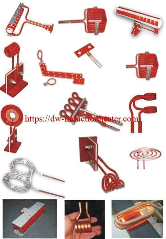
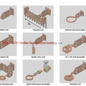
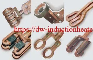
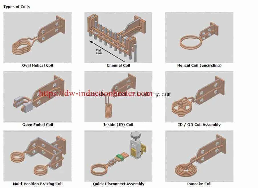
No matter what shape, size, or style induction coil you need, we can help you! Here are just a few of the hundreds of coil designs we have worked with. Pancake coils, helical coils, concentrator coils…square, round and rectangular tubing…Single-turn, five-turn, twelve-turn…under 0.10″ ID to over 5′ ID…for internal or external heating. Whatever your requirements, send us your drawings and specifications for a prompt quotation. If you’re new to induction heating, send us your parts for a free evaluation.
In a sense, coil design for induction heating is built upon a large store of empirical data whose development springs from several simple inductor geometries such as
the solenoid coil. Because of this, coil design is generally based on experience.
This series of articles reviews the fundamental electrical considerations in the design of inductors and describes some of the most common coils in use.
Basic design considerations
The inductor is similar to a transformer primary, and the workpiece is equivalent
to the transformer secondary (Fig.1). Therefore, several of the characteristics
of transformers are useful in the development of guidelines for coil design. One of the most important features of transformers is the fact that the efficiency
of coupling between the windings is inversely proportional to the square of the distance between them.In addition, the current in the primary of the transformer, multiplied by the number of primary turns, is equal to the current in the secondary, multiplied by the number of secondary turns. Because of these relationships, there are several conditions that should be kept in mind when designing any coil for
induction heating:
1) The coil should be coupled to the part as closely as feasible for maximum energy transfer. It is desirable that the largest possible number of magnetic flux lines intersect the workpiece at the area to be heated. The denser the flux at this point, the higher will be the current generated in the part.
2) The greatest number of flux lines in a solenoid coil are toward the center of the coil. The flux lines are concentrated
inside the coil, providing the maximum heating rate there.
3) Because the flux is most concentrated close to the coil turns themselves and decreases farther from them, the geometric center of the coil is a weak flux path. Thus, if a part were to be placed off center in a coil, the area closer to the coil turns would intersect a greater number of flux lines and would therefore be heated at a higher rate, whereas the area of the
part with less coupling would be heated at a lower rate; the resulting pattern is shown schematically in Fig. 2. This effect is more pronounced in high-frequency induction heating.
Induction Heating Coil Design and Basic Design
induction heating coils design
Related products
-

Induction aluminum billet preheat furnaces for forging extrusion and forming applications
-

Induction Heating for Disassembly and Assembly large bearings, shaft couplings, propeller hubs and Turbine Bearings in Shipbuilding Industry and Heavy Machinery Maintenance
-

Induction Brazing Coils
-

Steel Billet Heating Furnace with Induction For forging rolling mills and extrusion bars-billets-rods

