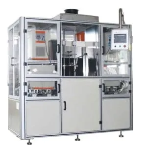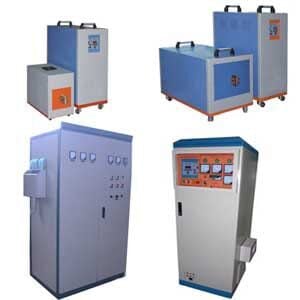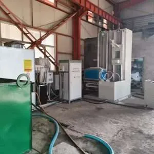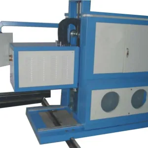


Induction Hardening Machine
Induction Hardening Machine for Steel Surface Hardening | Engineering Selection Guide
Product Summary
Quick Answer
What Is This Product?
Key Applications
Suitable Materials
Working Principle
Technical Specifications with 10 Models
Recommended Model Selection
Process Workflow
Coil and Fixture Design
Control System and Automation
Common Problems and Solutions
Engineering Selection Guide
Advantages
Limitations
Why Choose HLQ Induction Equipment?
FAQ
An induction hardening machine is a precision industrial system that uses electromagnetic induction to rapidly heat the surface layer of steel or cast iron components to the austenitizing temperature, followed by immediate quenching to produce a hard martensitic surface case while retaining a tough, ductile core. These machines are widely used in automotive, aerospace, tooling, mining, and general machinery manufacturing for hardening gears, shafts, camshafts, crankshafts, bearings, guide rails, and cutting tools. They solve critical buyer problems including premature surface wear, insufficient fatigue strength, inconsistent hardness depth, and the high energy cost and distortion risk associated with conventional furnace hardening.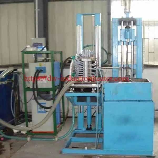
Quick Answer
An induction hardening machine is a solid-state IGBT-based power supply system paired with a precision induction coil and quench delivery system, designed to selectively harden the surface of steel and cast iron components to depths typically ranging from 0.5mm to 6mm, achieving surface hardness values of 55–65 HRC. It is best suited for high-volume production of wear-critical components such as automotive gears, transmission shafts, camshafts, and linear guide rails, where consistent case depth, minimal distortion, and fast cycle times are required.
What Is This Product?
An induction hardening machine is a specialized heat treatment system that applies the principle of electromagnetic induction to selectively harden the surface layer of metallic components — primarily medium-carbon steels, alloy steels, and cast irons — without affecting the core properties of the material. Unlike conventional furnace hardening, which heats the entire component uniformly, induction hardening delivers concentrated, precisely controlled heat only to the surface zone that requires hardness, leaving the core of the component in its original tough, ductile condition.
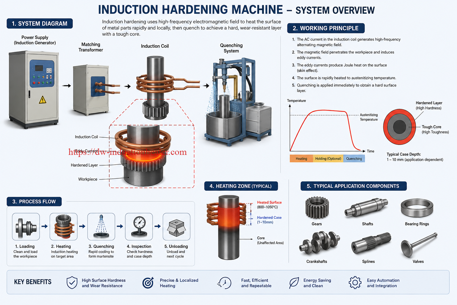
The machine consists of four primary subsystems: a solid-state induction power supply (typically IGBT-based, ranging from 10 kW to 500 kW), a custom-designed induction coil matched to the workpiece geometry, a quench delivery system (water-polymer quenchant spray ring or immersion tank), and a CNC-controlled workpiece handling and positioning system. Together, these subsystems execute a precisely timed heating and quenching cycle that produces a well-defined hardened case with a sharp transition to the soft core.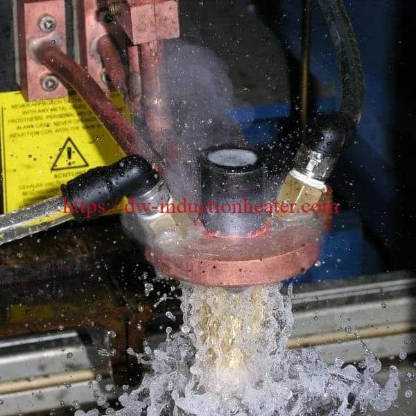
Modern induction hardening machines are available in several configurations to suit different production environments:
- Vertical CNC Induction Hardening Machines: The most common configuration for shaft, gear, and spindle hardening. The workpiece is held vertically and either scanned (progressive hardening) or single-shot hardened.
- Horizontal CNC Induction Hardening Machines: Used for long shafts, guide rails, and camshafts where vertical handling is impractical.
- Rotary Indexing Induction Hardening Machines: High-speed production systems for small components (bolts, pins, small gears) processed in a rotary carousel configuration.
- Portable Induction Hardening Machines: Compact, mobile units for on-site hardening of large, non-movable components such as crane rails, large gears, and machine tool beds.
- Integrated Induction Hardening and Tempering Lines: Fully automated production lines combining induction hardening with immediate induction tempering in a single pass.
Key Applications
Induction hardening machines are used across a broad spectrum of industries wherever surface wear resistance, fatigue strength, and contact stress resistance are critical engineering requirements:
- Automotive Manufacturing: Crankshafts, camshafts, transmission gears, drive shafts, CV joint components, steering rack teeth, valve seats, and wheel hub bearing races are among the most common automotive induction hardening applications. The automotive industry is the single largest user of induction hardening technology globally.
- Gearbox and Transmission Manufacturing: Gear tooth flanks and roots, spline shafts, and pinion gears require a hard, wear-resistant surface combined with a tough core to withstand cyclic contact stress and impact loading.
- Machine Tool Manufacturing: Linear guide rails, ball screw shafts, spindle journals, and machine bed slideways require a hard, smooth surface to maintain dimensional accuracy and resist wear over extended service life.
- Mining and Construction Equipment: Track pins, bucket teeth, drill rod connections, and crusher jaw components are induction hardened to resist the severe abrasive and impact wear conditions encountered in mining and earthmoving applications.
- Agricultural Machinery: Plow shares, tillage tools, harvester blades, and threshing components benefit from induction hardening to extend service life in abrasive soil conditions.
- Tooling and Die Manufacturing: Cutting tools, forming dies, punches, and mold components are induction hardened to improve wear resistance and tool life.
- Aerospace and Defense: Landing gear components, actuator shafts, and structural fasteners require precise, repeatable hardening with minimal distortion and full metallurgical traceability.
- Railway and Infrastructure: Rail ends, switch points, and axle journals are induction hardened to resist rolling contact fatigue and wear under heavy axle loads.
Suitable Materials
Induction hardening is applicable to materials that undergo a martensitic transformation upon rapid quenching from the austenitizing temperature. The carbon content of the material is the primary factor determining hardenability and achievable hardness. The following table summarizes the most common materials and their expected hardening results:
| Material | Carbon Content | Typical Hardness (HRC) | Case Depth Range | Notes |
|---|---|---|---|---|
| AISI 1040 / 1045 Carbon Steel | 0.40–0.45% | 54–58 | 1.0–4.0 mm | Most common induction hardening steel; excellent response |
| AISI 1050 / 1055 Carbon Steel | 0.50–0.55% | 56–60 | 1.0–4.0 mm | Higher hardness; slightly more brittle |
| AISI 4140 Alloy Steel (Cr-Mo) | 0.38–0.43% | 54–60 | 1.0–5.0 mm | Excellent hardenability; widely used for shafts and gears |
| AISI 4340 Alloy Steel (Ni-Cr-Mo) | 0.38–0.43% | 56–62 | 1.0–5.0 mm | High-strength aerospace and automotive applications |
| AISI 8620 Case Hardening Steel | 0.18–0.23% | 58–64 (after carburizing) | 0.5–2.0 mm | Typically carburized first, then induction hardened |
| AISI 52100 Bearing Steel | 0.98–1.10% | 60–65 | 0.5–2.0 mm | Bearing races and rolling elements; very high hardness |
| Gray Cast Iron (GCI) | 2.5–4.0% total C | 45–55 | 0.5–2.5 mm | Brake drums, cylinder liners; requires careful frequency selection |
| Ductile Cast Iron (DCI) | 3.0–4.0% total C | 50–58 | 0.5–2.5 mm | Crankshafts, camshafts in automotive engines |
| AISI D2 Tool Steel | 1.40–1.60% | 60–64 | 0.5–2.0 mm | Dies and cutting tools; requires precise temperature control |
| Stainless Steel 420 | 0.15–0.40% | 48–55 | 0.5–2.0 mm | Surgical instruments, cutlery; martensitic grade only |
Note: Austenitic stainless steels (304, 316) and aluminum alloys cannot be induction hardened as they do not undergo martensitic transformation.
Working Principle
The induction hardening process is governed by two fundamental physical phenomena: electromagnetic induction and the iron-carbon phase transformation. Understanding both is essential for the engineer designing or operating an induction hardening system.
Step 1: Electromagnetic Induction and Eddy Current Heating
When an alternating current flows through the induction coil, it generates a time-varying magnetic field in the space surrounding the coil. When a conductive workpiece is placed within or adjacent to this magnetic field, the changing flux induces an electromotive force (EMF) in the workpiece, which drives eddy currents through the workpiece material. These eddy currents flow against the electrical resistance of the steel, generating heat by Joule heating (P = I²R) directly within the surface layer of the workpiece.
Step 2: Skin Effect and Case Depth Control
The eddy currents are not uniformly distributed through the cross-section of the workpiece. Due to the skin effect, the current density is highest at the surface and decreases exponentially with depth. The reference depth of current penetration (skin depth, δ) is given by:
δ = 503 × √(ρ / (μr × f)) [mm]
Where ρ is the electrical resistivity of the material (Ω·m), μr is the relative magnetic permeability, and f is the frequency (Hz). For steel at room temperature (below the Curie point of ~768°C), μr is high (typically 50–200), which results in a shallow skin depth even at relatively low frequencies. Above the Curie temperature, μr drops to 1, and the skin depth increases dramatically. This means that the engineer can control the depth of heating — and therefore the case depth — primarily by selecting the appropriate operating frequency:
- High frequency (100–500 kHz): Very shallow case depth (0.5–1.5 mm); used for small gears, thin-walled components, and fine-pitch gear teeth.
- Medium-high frequency (30–100 kHz): Shallow to medium case depth (1.0–3.0 mm); used for medium gears, small shafts, and bearing races.
- Medium frequency (1–30 kHz): Medium to deep case depth (2.0–6.0 mm); used for large gears, heavy shafts, and deep case applications.
- Low frequency (50 Hz – 1 kHz): Very deep heating; used for through-hardening of large cross-sections or deep case requirements above 6mm.
Step 3: Austenitizing and Quenching
The surface of the steel workpiece is heated to the austenitizing temperature range (typically 820°C–980°C for medium-carbon steels) within a very short time (typically 1–10 seconds for most applications). The rapid heating rate means that the austenitizing temperature must be somewhat higher than for conventional furnace hardening, to allow sufficient time for carbon diffusion and homogeneous austenite formation despite the short heating cycle.
Immediately after the heating cycle, the workpiece surface is quenched by a high-velocity spray of water-polymer quenchant (typically 3–15% polyvinyl alcohol or polyalkylene glycol solution) delivered through a quench ring or spray block. The rapid cooling rate transforms the austenite in the surface layer to martensite — a hard, body-centered tetragonal crystal structure with high hardness (55–65 HRC). The core of the workpiece, which never reached the austenitizing temperature, remains in its original ferritic-pearlitic or tempered condition, retaining its toughness and ductility.
Technical Specifications
| Model | Output Power (kW) | Frequency Range | Input Voltage | Max Workpiece Temp (°C) | Heating Time | Case Depth Range | Cooling | CNC Axes | Notes |
|---|---|---|---|---|---|---|---|---|---|
| DW-UHF-10 | 10 | 100–500 kHz | 380V 3-phase | 1100 | 0.5–30 s | 0.3–1.5 mm | Water | — | Small parts, tools, pins |
| DW-UHF-30 | 30 | 50–200 kHz | 380V 3-phase | 1100 | 0.5–60 s | 0.5–2.0 mm | Water | 2 | Small gears, bearings, bolts |
| DW-UHF-60 | 60 | 30–100 kHz | 380V 3-phase | 1100 | 1–120 s | 1.0–3.0 mm | Water | 2 | Medium gears, shafts |
| DW-MF-110 | 100 | 8–30 kHz | 380V 3-phase | 1100 | 1–180 s | 2.0–5.0 mm | Water | 3 | Large gears, camshafts |
| DW-MF-160 | 160 | 4–15 kHz | 380V 3-phase | 1100 | 2–300 s | 2.5–6.0 mm | Water | 3 | Crankshafts, heavy shafts |
| DW-MF-200 | 200 | 2–10 kHz | 380V 3-phase | 1100 | 2–300 s | 3.0–7.0 mm | Water | 4 | Large industrial shafts, rolls |
| DW-MF-250 | 250 | 1–8 kHz | 380V 3-phase | 1100 | 3–600 s | 4.0–8.0 mm | Water | 4 | Heavy mining components |
| DW-MF-300 | 300 | 0.5–5 kHz | 380V 3-phase | 1100 | 5–600 s | 5.0–10.0 mm | Water | 4 | Large gears, rail hardening |
| DW-MF-400 | 400 | 0.5–3 kHz | 380V 3-phase | 1100 | 5–600 s | 6.0–12.0 mm | Water | 5 | Heavy industrial rolls, large shafts |
| DW-MF-500 | 500 | 0.2–2 kHz | 380V 3-phase | 1100 | 10–900 s | 8.0–15.0 mm | Water | 5 | Very large components, deep case |
Recommended Model Selection
| Application | Material | Component Size | Recommended Model | Recommended Power | Frequency |
|---|---|---|---|---|---|
| Small gear tooth hardening | AISI 1045 | Module 1–3, OD < 80mm | DW-UHF-30 | 30 kW | 100–200 kHz |
| Medium gear contour hardening | AISI 4140 | Module 3–6, OD 80–200mm | DW-UHF-60 | 60 kW | 30–80 kHz |
| Large gear tooth hardening | AISI 4340 | Module 6–12, OD 200–600mm | DW-MF-160 | 160 kW | 4–10 kHz |
| Automotive camshaft journal | Ductile cast iron | Dia 25–50mm | DW-MF-110 | 100 kW | 10–30 kHz |
| Crankshaft pin and journal | AISI 1050 / DCI | Dia 40–100mm | DW-MF-160 | 160 kW | 8–20 kHz |
| Linear guide rail hardening | AISI 1045 | Width 15–60mm, length up to 3m | DW-MF-110 | 100 kW | 8–30 kHz |
| Ball screw shaft hardening | AISI 52100 | Dia 20–80mm | DW-UHF-60 | 60 kW | 30–100 kHz |
| Mining track pin hardening | AISI 4140 | Dia 40–80mm, length 100–300mm | DW-MF-200 | 200 kW | 4–10 kHz |
| Cutting tool edge hardening | AISI D2 tool steel | Thickness 3–15mm | DW-UHF-10 | 10 kW | 200–500 kHz |
| Railway rail end hardening | High carbon rail steel | Rail head width 60–75mm | DW-MF-300 | 300 kW | 1–5 kHz |
Process Workflow
A properly executed induction hardening process follows a well-defined sequence of steps. Each step must be controlled and documented for quality assurance purposes.
- Pre-process Inspection and Preparation: Verify that the workpiece material grade, hardness (pre-hardening), surface condition, and dimensional tolerances meet the process specification. Remove any surface contamination (oil, scale, rust) that could interfere with quench delivery or cause surface defects. Confirm that the workpiece has been pre-tempered or normalized as required by the process specification.
- Coil Installation and Setup: Install the correct induction coil for the workpiece geometry. Verify the coil-to-workpiece gap (typically 1.5–4mm for most applications). Check cooling water flow through the coil. Install the quench ring or spray block and verify quench nozzle alignment and flow rate.
- Process Parameter Setup: Enter the process parameters into the CNC controller: power level (kW), frequency (kHz), heating time or scan speed (mm/s), quench delay time (ms), quench flow rate, and workpiece rotation speed (RPM for shaft hardening).
- First Article Trial Run: Run the first workpiece through the complete hardening cycle. After quenching, allow the workpiece to cool to ambient temperature before inspection.
- First Article Inspection: Perform hardness testing (Rockwell HRC at surface and at multiple depths via cross-section), case depth measurement (by metallographic cross-section etching with Nital reagent), and visual inspection for cracks, soft spots, and surface defects. Confirm that all results meet the engineering specification before approving the process for production.
- Production Run: Process production workpieces using the approved parameters. Monitor key process variables (power, frequency, temperature if pyrometer is fitted, quench flow rate) continuously. Perform periodic in-process hardness checks as specified by the quality plan.
- Post-hardening Tempering: Induction-hardened components must be tempered within a defined time window (typically within 4 hours of quenching) to relieve quench stresses and reduce the risk of delayed cracking. Tempering is typically performed in a batch oven at 150°C–200°C for 1–2 hours, or by induction tempering immediately after hardening.
- Final Inspection and Documentation: Perform final hardness testing, dimensional inspection (to verify distortion is within tolerance), and crack detection (magnetic particle inspection or dye penetrant inspection). Record all process parameters and inspection results for traceability.

Coil and Fixture Design
The induction coil is the most critical component of the induction hardening system. Its geometry, material, and design directly determine the heating pattern, case depth uniformity, and the ability to achieve the required hardness profile on a specific workpiece.
Coil Types for Hardening
- Encircling (Solenoid) Coil: The most common type for shaft and cylindrical component hardening. The workpiece passes through the center of the coil. Provides uniform circumferential heating. Used for scan hardening of shafts, pins, and tubes.
- Single-Turn or Multi-Turn Encircling Coil: Used for single-shot hardening of short cylindrical sections (bearing journals, shaft steps). Multi-turn coils provide more uniform axial temperature distribution.
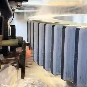
- Gear Tooth Coil (Contour Coil): Designed to follow the contour of gear teeth, providing uniform case depth on both the tooth flank and root. Critical for achieving a true contour-hardened gear profile rather than a simple through-hardened tooth.
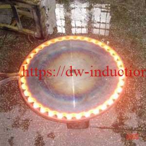
- Flat (Pancake) Coil: Used for hardening flat surfaces such as guide rails, machine beds, and flat tool surfaces. The coil is scanned across the surface.
- Internal (ID) Coil: Used for hardening the bore of cylinders, rings, and bearing housings. Requires careful design to manage the reflected impedance and ensure adequate power transfer.
- Split Coil: A coil that can be opened to allow loading of complex workpieces that cannot be inserted axially into an encircling coil.
Coil Material and Construction
Induction hardening coils are fabricated from copper tubing (typically 6–16mm OD, wall thickness 1.0–1.5mm) through which cooling water flows continuously during operation. The coil is formed into the required geometry by bending, and the turns are insulated from each other with high-temperature epoxy or ceramic coating. For high-power, high-frequency applications, the coil may be silver-brazed to a copper bus bar assembly for improved electrical contact and mechanical rigidity.
Coil-to-Workpiece Gap
The gap between the coil and the workpiece surface is a critical parameter. A smaller gap increases the coupling efficiency and power transfer, resulting in faster heating and a shallower case. A larger gap reduces coupling efficiency but may improve temperature uniformity for complex geometries. For most shaft and gear hardening applications, a gap of 1.5–4mm is typical. The gap must be maintained consistently throughout the hardening cycle; variations in gap due to workpiece runout or positioning errors will cause corresponding variations in case depth.
Control System and Automation
Modern induction hardening machines are equipped with sophisticated CNC control systems that automate the entire hardening cycle and provide comprehensive process monitoring and data logging for quality assurance.
CNC Axis Control
CNC induction hardening machines typically feature 2–5 controlled axes: vertical (Z-axis) for scan speed control, rotational (C-axis) for workpiece rotation during shaft hardening, horizontal (X-axis) for coil positioning, and additional axes for quench ring positioning and workpiece loading/unloading. The CNC controller coordinates all axis movements with the power supply output and quench system activation to execute the programmed hardening cycle with high repeatability.
Power Supply Control
The IGBT-based power supply is controlled by a dedicated DSP (Digital Signal Processor) that regulates output power, frequency, and current in real time. The power supply can operate in constant power mode, constant current mode, or constant voltage mode, depending on the application requirements. For scan hardening of shafts with varying cross-sections, constant power mode is typically used to maintain consistent energy input per unit length as the coil traverses the workpiece.
Temperature Monitoring
Optical pyrometers (infrared temperature sensors) are increasingly integrated into induction hardening machines to provide real-time surface temperature feedback. The pyrometer signal can be used in a closed-loop control scheme to adjust power output and maintain a consistent austenitizing temperature, compensating for variations in workpiece material, surface condition, and coupling efficiency between parts.
Process Data Logging
All process parameters — power, frequency, scan speed, rotation speed, quench flow rate, temperature (if pyrometer-equipped), and cycle time — are recorded for every workpiece processed. This data is stored in a database with a unique workpiece identifier, providing full traceability for quality audits and failure analysis. Data can be exported to CSV, PDF, or connected to plant MES/ERP systems via OPC-UA or Modbus TCP protocols.
Common Problems and Solutions
| Problem | Likely Cause | Engineering Solution |
|---|---|---|
| Soft spots on hardened surface | Quench flow obstruction; coil gap variation; surface contamination (oil/scale) | Inspect and clean quench nozzles; check workpiece runout; clean workpiece surface before hardening |
| Case depth too shallow | Frequency too high; power too low; scan speed too fast; heating time too short | Reduce frequency; increase power; reduce scan speed; increase heating time |
| Case depth too deep | Frequency too low; power too high; scan speed too slow; heating time too long | Increase frequency; reduce power; increase scan speed; reduce heating time |
| Surface cracking after hardening | Quench rate too severe; carbon content too high; tempering delayed; stress concentration at geometry transition | Reduce quenchant concentration; temper within 1 hour of quenching; add radius at sharp transitions; preheat before hardening for high-carbon steels |
| Excessive distortion | Non-uniform heating; asymmetric quench; workpiece not rotating during scan hardening | Verify coil concentricity; check quench ring symmetry; ensure workpiece rotation is active during scan hardening |
| Coil overheating / coil failure | Insufficient cooling water flow; coil-to-workpiece gap too small; coil damage | Verify water flow rate and inlet temperature; increase coil gap; inspect coil for cracks and replace if damaged |
| Hardness below specification | Austenitizing temperature too low; quench delay too long; quenchant concentration incorrect; wrong material grade | Increase power or heating time; reduce quench delay to < 0.5 seconds; verify quenchant concentration; confirm material certificate |
| Inconsistent hardness between parts | Workpiece positioning variation; power supply drift; quench flow rate variation | Implement positive workpiece stop; calibrate power supply; install quench flow meter with alarm |
Engineering Selection Guide
Selecting the correct induction hardening machine requires a systematic engineering evaluation of the following parameters:
1. Define the Required Case Depth
The required case depth (effective case depth to 50 HRC, or total case depth to the hardness transition) is the primary driver for frequency selection. Use the skin depth formula and empirical data for your material to select the appropriate frequency range. As a general rule: case depth ≈ 1.5–2.5 × skin depth at the operating frequency.
2. Calculate Required Power
Required power depends on the heated surface area, the required heating rate, and the thermal properties of the material. A practical engineering estimate for steel is:
P (kW) = A (cm²) × p (kW/cm²)
Where A is the heated surface area and p is the specific power density (typically 0.5–2.0 kW/cm² for scan hardening, 1.0–5.0 kW/cm² for single-shot hardening). Higher power density enables faster heating and shallower case depth for a given frequency.
3. Select Single-Shot vs. Scan Hardening
- Single-shot hardening: The entire hardening zone is heated simultaneously and quenched in one operation. Best for short components (bearing journals, small gears) where uniform heating of the entire zone is achievable. Faster cycle time but requires a coil matched to the exact zone length.
- Scan hardening: The coil traverses the workpiece at a controlled speed, progressively heating and quenching. Best for long components (shafts, guide rails) and for achieving consistent case depth along the full length. More flexible but slower than single-shot.
4. Determine Automation Level
For high-volume production (> 500 parts/day), invest in a fully automated CNC machine with robotic loading/unloading and integrated tempering. For medium volume (50–500 parts/day), a semi-automatic CNC machine with manual loading is appropriate. For low volume or prototype work, a manually operated machine with basic PLC control is sufficient.
5. Quench System Selection
Select the quench system based on the required quench severity and the workpiece geometry. Water-polymer quenchants (3–10% PAG or PVA) are standard for most steel hardening applications. Pure water quenching is used for cast iron and some low-alloy steels. Oil quenching is rarely used for induction hardening due to fire risk and environmental concerns.
Advantages
- Selective Surface Hardening: Only the surface layer that requires hardness is treated, preserving the tough, ductile core. This combination of hard surface and tough core is superior to through-hardening for components subject to both wear and impact loading.
- Minimal Distortion: Because only a thin surface layer is heated and the bulk of the workpiece remains cool, thermal distortion is significantly lower than for furnace hardening. This reduces or eliminates post-hardening grinding allowance.
- Fast Cycle Time: Induction hardening cycles are measured in seconds to minutes, compared to hours for furnace hardening. This enables integration into high-speed production lines.
- Energy Efficiency: Heat is generated only in the workpiece surface layer that requires treatment, not in the entire component or the furnace atmosphere. Overall energy consumption per part is typically 60–80% lower than furnace hardening.
- Excellent Repeatability: CNC-controlled process parameters ensure consistent case depth, hardness, and pattern from part to part, enabling process capability indices (Cpk) well above 1.33 for high-volume automotive production.
- No Atmosphere Control Required: Unlike vacuum or gas-atmosphere furnace hardening, induction hardening is performed in air. No protective atmosphere is required, simplifying the process and reducing operating cost.
- In-Line Integration: Induction hardening machines can be integrated directly into manufacturing cells and production lines, eliminating the need to batch transport parts to a separate heat treatment facility.
- Compressive Residual Stresses: The martensitic transformation in the surface layer produces beneficial compressive residual stresses, which significantly improve fatigue strength and resistance to stress corrosion cracking.
Limitations
- Material Limitations: Induction hardening is only effective for materials with sufficient carbon content (typically > 0.35% C) to form martensite. Austenitic stainless steels, aluminum, copper, and low-carbon steels cannot be induction hardened.
- Coil Design Complexity: Each unique workpiece geometry requires a custom-designed induction coil. Coil design for complex geometries (e.g., contour hardening of helical gears) requires significant engineering expertise and iterative development. Coil changeover time can be significant in low-volume, high-mix production environments.
- Case Depth Limitations: Achieving case depths greater than 8–10mm by induction hardening is difficult and requires very high power at low frequency. For very deep case requirements, carburizing or through-hardening may be more practical.
- End Effect and Edge Effect: At the ends of a scan-hardened zone and at geometric discontinuities (shoulders, holes, keyways), the heating pattern is distorted by electromagnetic end effects, resulting in under-hardened or over-hardened zones. These effects must be managed by coil design and process parameter adjustments.
- Capital Cost: A fully equipped CNC induction hardening machine represents a significant capital investment (USD 50,000–500,000+ depending on power and automation level), which may not be justified for low-volume production.
- Operator and Process Engineering Expertise: Developing a new induction hardening process for a new component requires significant metallurgical and electromagnetic engineering expertise. Process development time (first article approval) can take days to weeks for complex components.
Why Choose HLQ Induction Equipment?
HLQ Induction Equipment is a specialized manufacturer of industrial induction heating systems with over 15 years of focused engineering experience in induction hardening, brazing, forging, and heat treatment applications. Here is why leading automotive suppliers, gear manufacturers, and machine tool builders choose HLQ:
- Complete Induction Hardening System Supply: HLQ supplies the complete system — IGBT power supply, CNC machine, induction coil, quench system, and control software — from a single source, ensuring full system integration and eliminating compatibility issues between components from different suppliers.
- Custom Coil Engineering: HLQ’s in-house coil design team develops custom induction coils for any workpiece geometry, from simple shaft coils to complex contour-hardening coils for helical gears and crankshafts. Coil development includes electromagnetic simulation, prototype fabrication, and process validation.
- Process Development Support: HLQ provides comprehensive process development support, including first article testing at HLQ’s laboratory, metallurgical analysis (hardness testing, case depth measurement, microstructure examination), and process parameter optimization before machine delivery.
- Wide Power Range: HLQ’s induction hardening machines cover power ranges from 10 kW to 500 kW and frequency ranges from 200 Hz to 500 kHz, covering all induction hardening applications from small precision tools to large industrial components.
- Automation Integration: HLQ designs and builds fully automated induction hardening cells with robotic loading/unloading, conveyor integration, automatic quench concentration monitoring, and MES data connectivity for Industry 4.0 production environments.
- Global After-Sales Support: HLQ provides remote diagnostics, spare parts supply, and on-site service support globally. All machines are supplied with comprehensive English-language documentation, wiring diagrams, and operator training.
FAQ
Q1: What is the difference between induction hardening and case hardening (carburizing)?
A: Induction hardening heats the surface of a medium-to-high carbon steel component above the austenitizing temperature and quenches it to form martensite. It relies on the carbon already present in the base material. Case hardening (carburizing) is a thermochemical process that first adds carbon to the surface of a low-carbon steel by exposing it to a carbon-rich atmosphere at high temperature (typically 900–950°C for 4–20 hours), and then quenches the carburized layer to form martensite. Induction hardening is faster and produces less distortion, but requires a medium-to-high carbon base material. Carburizing allows the use of low-carbon steels (which have better core toughness) and can achieve very deep case depths, but requires long furnace cycle times and produces more distortion.
Q2: What hardness can be achieved by induction hardening?
A: The achievable surface hardness depends primarily on the carbon content of the material. For medium-carbon steels (0.40–0.55% C) such as AISI 1045 and 4140, typical surface hardness after induction hardening is 54–60 HRC. For high-carbon steels (0.60–1.10% C) such as AISI 52100 bearing steel, hardness of 60–65 HRC is achievable. For cast irons, hardness of 45–58 HRC is typical depending on the microstructure and carbon form.
Q3: How deep can induction hardening penetrate?
A: The effective case depth achievable by induction hardening ranges from approximately 0.3mm (at very high frequencies of 400–500 kHz) to 10–15mm (at very low frequencies of 200–500 Hz with high power). For the most common industrial applications (gear and shaft hardening), case depths of 1.0–6.0mm are typical. Case depths greater than 8mm are technically achievable but require very high power at low frequency and become increasingly difficult to control uniformly.
Q4: Is tempering always required after induction hardening?
A: Yes, tempering after induction hardening is strongly recommended and is required by most engineering specifications. The as-quenched martensitic structure is very hard but also very brittle and contains high residual tensile stresses that can cause delayed cracking. Tempering at 150°C–200°C for 1–2 hours relieves these stresses and reduces brittleness without significantly reducing surface hardness. For some applications (e.g., bearing races), self-tempering by the residual heat in the core of the workpiece may be acceptable, but controlled oven or induction tempering is preferred for critical components.
Q5: Can induction hardening be applied to stainless steel?
A: Only martensitic stainless steels (such as AISI 410, 420, and 440C) can be induction hardened, as they contain sufficient carbon and undergo a martensitic transformation upon quenching. Austenitic stainless steels (304, 316, 321) cannot be hardened by any quench-and-temper process, including induction hardening, because they do not undergo a martensitic transformation. Ferritic stainless steels have limited hardenability and are generally not suitable for induction hardening.
Q6: What quenchant should be used for induction hardening?
A: The most common quenchant for induction hardening of carbon and alloy steels is a water-polymer solution, typically 3–10% polyalkylene glycol (PAG) or polyvinyl alcohol (PVA) in water. The polymer concentration controls the quench severity: higher concentration = slower quench = lower risk of cracking but potentially lower hardness. Pure water provides the most severe quench and is used for cast irons and some low-alloy steels. Oil quenching is rarely used for induction hardening due to fire risk and environmental concerns. The quenchant temperature should be maintained at 20–40°C for consistent results.
Q7: How long does an induction hardening cycle take?
A: Cycle time depends on the component size, required case depth, and hardening method. For single-shot hardening of small components (bearing journals, small gear teeth), the heating time is typically 1–5 seconds, with a total cycle time (including loading, heating, quenching, and unloading) of 10–30 seconds. For scan hardening of long shafts (500–1000mm), the total cycle time is typically 30–120 seconds. For very large components (large gears, heavy rolls), the cycle time may be several minutes. In all cases, induction hardening is dramatically faster than furnace hardening, which requires hours per batch.