

stress relief heat treatment with induction
Induction Stress Relief Heat Treatment System for Welded Steel and Pipelines
Induction stress relief heat treatment is a controlled thermal process used to reduce residual stresses in suitable welded steel components, pipelines, pressure-containing equipment and fabricated metal structures.
The HLQ MYD induction heating series includes six published industrial models: MYD-40, MYD-50, MYD-60, MYD-80, MYD-100 and MYD-120, with nominal output power ratings from 40 kW to 120 kW.
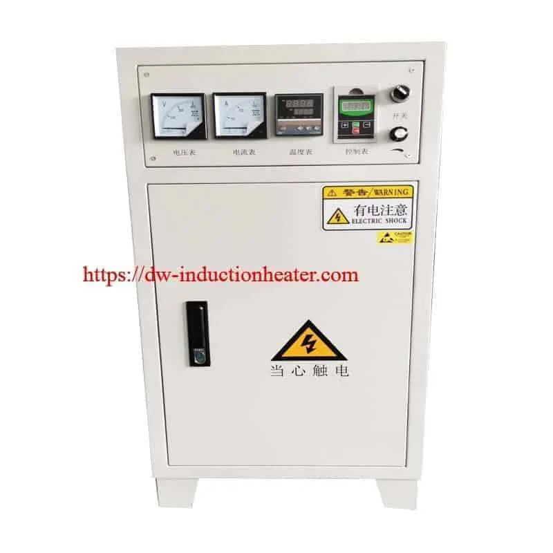
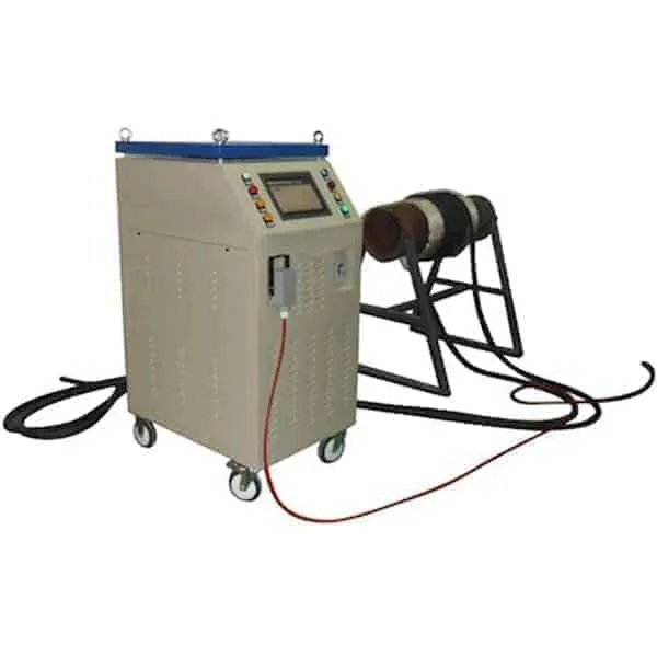
These systems use IGBT induction power conversion, application-specific induction heating coils, PLC touchscreen control and temperature-monitoring equipment for industrial heating operations.
For stress-relief applications, the induction heater supplies heat to a selected metal region while thermocouples monitor the temperature response. The thermal procedure may include controlled heating, soaking at a specified temperature and controlled cooling.
Successful stress relief depends on the workpiece material, original heat-treatment condition, component dimensions, heating-zone width, temperature distribution and qualified thermal cycle.
Important: Induction equipment can provide the heat required for suitable stress-relief procedures, but the equipment itself does not determine whether a particular thermal cycle complies with a welding or pressure-equipment standard.
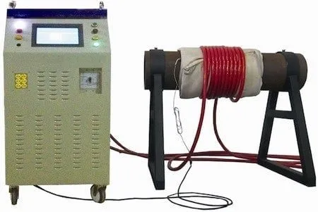
Quick Answer
What Is Induction Stress Relief Heat Treatment?
Induction stress relief heat treatment uses electromagnetic induction to heat selected regions of conductive metal according to a controlled thermal cycle intended to reduce residual stresses.
The process is commonly associated with welded steel structures, industrial pipelines, pressure equipment and selected fabricated components.
The HLQ MYD industrial series has published nominal power ratings from 40 kW to 120 kW and an output frequency range of 2–36 kHz.
The published system features include IGBT power conversion, PLC touchscreen operation, multi-point temperature monitoring and optional temperature recording equipment.
Typical thermal sequence: Controlled Heating → Soaking Temperature → Holding Period → Controlled Cooling.
Engineering limitation: There is no single stress-relief temperature or holding time suitable for every steel. Actual thermal cycles must be determined from the material grade, thickness, original mechanical properties and applicable procedure.
Quick Technical Overview
| Technical Item | HLQ Published Information | Engineering Consideration |
|---|---|---|
| Equipment Series | MYD Industrial Induction Heating | Model-specific configuration |
| Nominal Output Power | 40–120 kW | Continuous capacity requires verification |
| Published Output Frequency | 2–36 kHz | Depends on induction load and coil configuration |
| Standard Input | Three-Phase 380 V | Confirm rated current and input frequency |
| Power Electronics | IGBT | Induction power conversion |
| Control Interface | PLC Touchscreen | Actual programmable functions require confirmation |
| Temperature Monitoring | Published Six-Channel Capability | Confirm sensor channels and independent control zones |
| Main Applications | Industrial Steel Heating and Selected PWHT | Approved thermal procedure required |
Table of Contents
- What Is Induction Stress Relief Heat Treatment?
- Key Applications
- Suitable Materials
- Working Principle
- Technical Specifications
- Recommended Model Selection
- Process Workflow
- Common Problems and Solutions
- Engineering Selection Guide
- Advantages and Limitations
- Why Choose HLQ?
- 10 Core FAQs
What Is Induction Stress Relief Heat Treatment?
Stress relief heat treatment is a controlled heating and cooling process intended to reduce residual stresses created by welding, fabrication, forming, machining or other manufacturing operations.
Welding produces nonuniform heating and cooling. Different regions of the workpiece expand and contract at different times, potentially leaving residual stresses after the component returns to ambient temperature.
When a suitable steel is heated according to an approved thermal procedure, time-dependent material behavior can allow some residual stresses to relax.
The amount and distribution of stress reduction depend on the material properties, temperature, holding time, restraint and geometry of the component.
Induction heating provides one method of supplying the required thermal energy.
Rather than transferring all heat from an external furnace atmosphere or combustion flame, an induction system generates electrical currents inside the conductive metal through a changing magnetic field.
What Causes Residual Stress in Welded Steel?
| Cause | Physical Mechanism | Possible Consequence |
|---|---|---|
| Nonuniform Weld Heating | Local expansion occurs while surrounding material remains cooler. | Thermal strain and localized stress |
| Nonuniform Cooling | The weld and adjacent metal contract at different rates. | Residual tensile and compressive stresses |
| Joint Restraint | Connected components restrict thermal expansion and contraction. | Higher local restraint stresses |
| Phase Transformation | Changes in steel microstructure may alter local volume. | Additional transformation-related stresses |
| Fabrication and Forming | Plastic deformation creates nonuniform strain. | Residual stress before welding |
Stress Relief Versus Preheating Versus PWHT
| Process | When Performed | Primary Objective | Key Control Requirement |
|---|---|---|---|
| Welding Preheating | Before welding | Establish specified welding temperature | Minimum preheat temperature |
| Interpass Temperature Control | Between weld passes | Manage weld-area temperature | Permitted temperature range |
| Postheating | After welding, when specified | Apply an approved post-weld heating process | Specified temperature and duration |
| Stress Relief Heat Treatment | Usually after fabrication or welding | Reduce selected residual stresses | Temperature, time and cooling conditions |
| Post-Weld Heat Treatment | After welding | Apply a qualified thermal treatment | Complete approved thermal cycle and records |
Stress relieving is one possible objective of PWHT, but not every PWHT operation has the same metallurgical purpose.
For complete post-weld heating systems and associated equipment, see HLQ induction post-weld heat treatment equipment.
Key Applications
1. Stress Relief of Welded Steel Pipes
Industrial piping systems may require post-weld thermal treatment when specified by the material standard, design code, engineering specification or approved welding procedure.
Flexible induction heating cables can be arranged around suitable insulated pipe sections to provide localized heating.
The heating configuration must account for pipe outside diameter, wall thickness, heating band width, axial temperature gradients and temperature distribution around the circumference.
For critical piping, local PWHT requirements may also specify minimum heated-band dimensions and restrictions on temperature gradients.
2. Oil and Gas Pipeline Welding
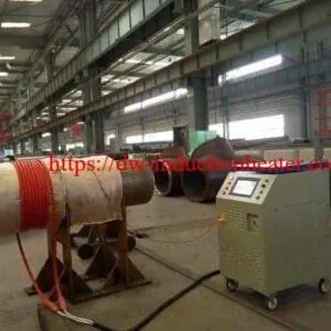
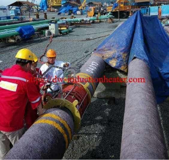
Induction heating systems can be evaluated for selected pipeline heating and post-weld thermal treatment operations.
Pipeline applications require careful control of temperature-sensor positioning, coil installation, electrical supply and site safety.
Material grade, service conditions and applicable welding requirements determine whether stress-relief treatment is appropriate.
3. Pressure Vessel Weld Heat Treatment
Some pressure equipment requires heat treatment after welding in accordance with the applicable construction code and material requirements.
Induction heating can be considered for suitable local treatment arrangements when permitted by the governing procedure.
However, local heating of a vessel shell or nozzle may introduce temperature gradients and restraint effects that must be evaluated.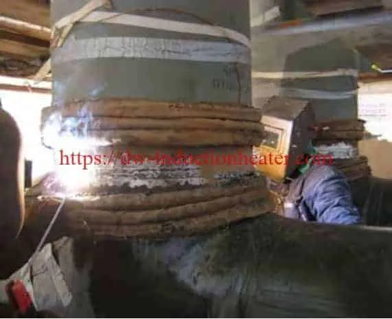
Related applications are described in HLQ induction heating for pressure vessels.
4. Industrial Boiler and Steam Piping Components
Selected industrial boiler components and high-temperature piping welds may require specified thermal treatment.
The selected cycle depends on material composition, section thickness and applicable requirements.
Temperature monitoring is particularly important when multiple materials, thicknesses or welded attachments are present.
5. Structural Steel Fabrication
Large fabricated steel assemblies may contain residual stresses resulting from welding, forming or heavy machining.
Localized induction heating may be evaluated when the material, component geometry and treatment requirements permit it.
However, reducing residual stress in one region does not guarantee that all residual stresses throughout the complete structure are removed.
6. Industrial Weld Repair
Some repair-welding procedures require specific heating after welding to manage material condition and residual stresses.
Induction heating may be suitable for accessible metal regions if the required thermal cycle can be controlled and documented.
The repair procedure must establish the treatment temperature, permitted heating rate, holding time and cooling requirements.
Application Comparison
| Application | Heating Objective | Critical Engineering Requirement |
|---|---|---|
| Pipeline Welds | Apply the specified localized thermal cycle | Band width, circumferential uniformity and procedure |
| Pressure Vessels | Meet specified thermal treatment requirements | Material, construction code and local heating limitations |
| Boiler Components | Perform approved post-weld thermal treatment | Alloy grade and temperature control |
| Structural Steel | Reduce selected fabrication-related residual stresses | Component restraint and mechanical properties |
| Industrial Weld Repairs | Follow qualified repair treatment | Repair procedure and temperature records |
| Large Cylindrical Components | Heat a selected circumferential region | Thermal gradients and coil geometry |
Suitable Materials
Induction heating can generate heat in electrically conductive metals, but the suitability of a stress-relief thermal cycle depends on the material’s metallurgy and mechanical properties.
For some steels, heating at an unsuitable temperature can change hardness, strength, toughness or corrosion-related properties.
Material Suitability Matrix
| Material | Induction Heating Suitability | Stress Relief Consideration |
|---|---|---|
| Carbon Steel | Generally Suitable | Use material- and procedure-specific thermal cycle |
| Structural Steel | Generally Suitable for Heating | Assess original properties and treatment requirements |
| Low-Alloy Steel | Application-Dependent | Temperature limits depend on alloy composition |
| Cr-Mo Alloy Steel | Conditional | May require tightly controlled PWHT parameters |
| Quenched and Tempered Steel | Special Evaluation Required | Excessive heating may reduce strength or hardness |
| High-Strength Low-Alloy Steel | Conditional | Review mechanical property requirements |
| Austenitic Stainless Steel | Requires Engineering Evaluation | Potential sensitization and grade-specific restrictions |
| Ferritic Stainless Steel | Conditional | Grade-specific microstructural considerations |
| Cast Iron | Special Evaluation Required | Thermal gradients and cracking sensitivity |
Important Material Properties
| Material Property | Effect on Heat Treatment |
|---|---|
| Electrical Resistivity | Influences induction heating behavior |
| Magnetic Permeability | Affects electromagnetic coupling |
| Thermal Conductivity | Controls heat spreading through the component |
| Specific Heat Capacity | Determines required sensible heat |
| Yield Strength at Temperature | Influences stress relaxation behavior |
| Original Tempering Temperature | May restrict subsequent heat-treatment temperature |
| Section Thickness | Affects heat-up time and temperature gradients |
| Metallurgical Condition | Determines sensitivity to additional thermal treatment |
Important: Do not use a generic stress-relief temperature for all steels. The temperature and thermal cycle must follow the applicable material and heat-treatment procedure.
Working Principle
How Does Induction Stress Relief Heat Treatment Work?
An induction heating generator converts industrial electrical power into high-frequency alternating current.
The high-frequency current flows through an induction heating coil arranged around or near the conductive workpiece.
The coil generates a changing magnetic field.
This magnetic field induces electrical currents inside the metal, where electrical resistance converts electromagnetic energy into heat.
The workpiece temperature is monitored by thermocouples positioned at the required measurement locations.
The heating controller adjusts available power-control functions to follow the specified thermal process.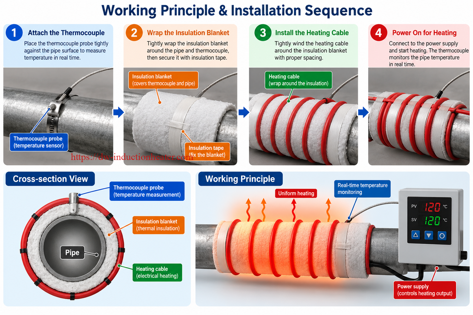
Induction Heating Process
| Stage | Operation | Result |
|---|---|---|
| 1 | Three-Phase Electrical Input | Supplies power to the induction generator |
| 2 | IGBT Power Conversion | Produces high-frequency electrical output |
| 3 | Induction Coil Energization | Creates an alternating magnetic field |
| 4 | Eddy Current Generation | Induces electrical current within the workpiece |
| 5 | Resistance Heating | Generates heat inside the conductive metal |
| 6 | Temperature Measurement | Thermocouples measure specified metal temperatures |
| 7 | Thermal Cycle Control | Supports controlled heating and holding functions |
| 8 | Controlled Cooling | Completes the approved treatment cycle |
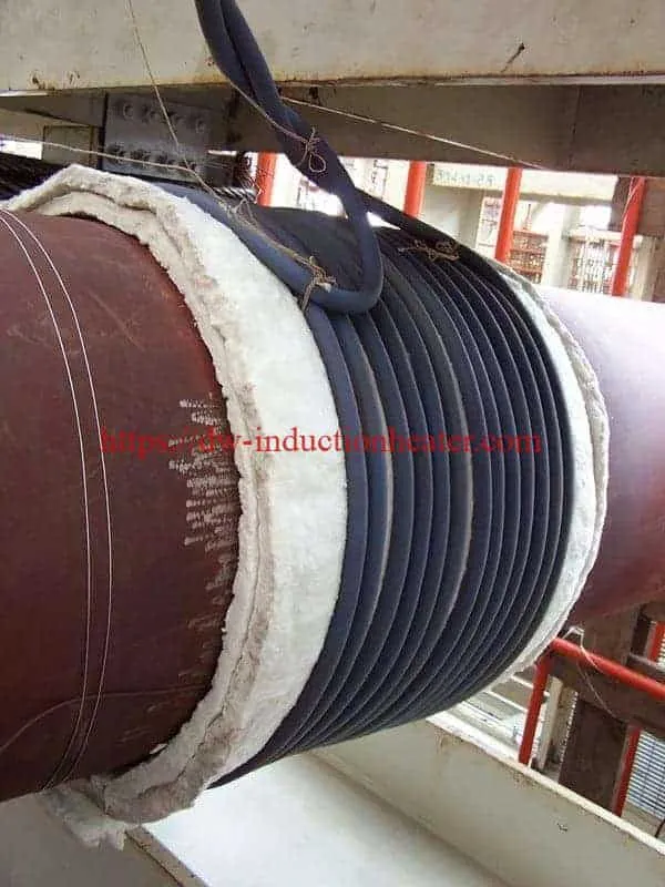
Correct Installation of Thermocouples and Induction Heating Cables
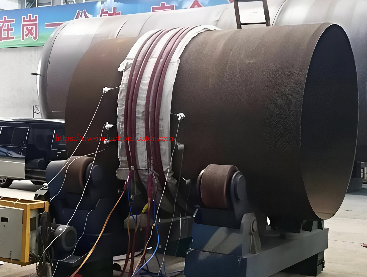
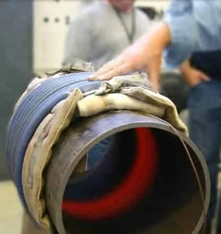
For a typical insulated steel-pipe heating arrangement, the installation sequence must maintain direct thermocouple contact with the metal surface.
Correct installation sequence:
- Prepare and clean the steel pipe surface.
- Attach K-type thermocouples directly to the steel at the specified measurement positions.
- Cover the steel pipe and thermocouples with suitable thermal insulation blankets.
- Wrap the insulation blankets tightly and secure them with approved non-metallic, high-temperature insulating fabric straps.
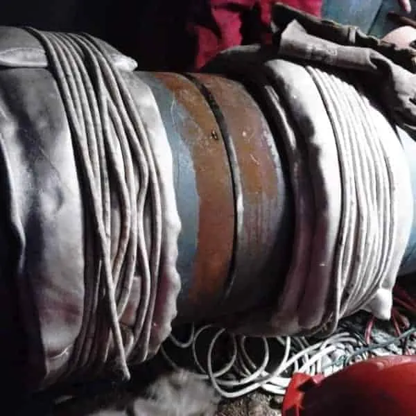
- Wind the flexible induction heating cable around the outside of the insulation blanket.
- Secure the heating cable with approved electrically insulating fixing materials.
- Connect the heating cable and thermocouple leads to the appropriate equipment terminals.
- Verify electrical safety, sensor readings, coil arrangement and cooling conditions before energizing the system.
Correct Pipe Heating Layer Arrangement
| Position | Component | Function |
|---|---|---|
| 1 – Inner Workpiece | Steel Pipe | Conductive metal heated by electromagnetic induction |
| 2 – Direct Metal Contact | Thermocouple Junctions | Measure actual workpiece temperature |
| 3 – Middle Layer | Thermal Insulation Blankets | Cover the thermocouples and reduce heat loss |
| 4 – Insulation Fixing | Non-Metallic Insulating Straps | Hold the insulation firmly in position |
| 5 – Outer Heating Layer | Flexible Induction Heating Cable | Generates the alternating magnetic field |
Safety requirement: Do not use unapproved metallic straps, steel wires or conductive fixing bands in the energized induction-heating zone.
Metallic fixing materials may experience unwanted induction heating and create additional hazards.
For alternative coil constructions and compatible accessories, see HLQ flexible induction heating cables.
Four Stages of a Stress Relief Thermal Cycle
| Stage | Purpose | Engineering Requirement |
|---|---|---|
| Controlled Heating | Increase workpiece temperature according to the procedure | Maximum permitted heating rate and temperature gradients |
| Soaking Temperature | Reach the specified treatment temperature | All required measurement locations must meet the applicable limits |
| Holding Period | Maintain the specified thermal conditions | Required soaking time and temperature uniformity |
| Controlled Cooling | Reduce temperature according to the approved procedure | Cooling-rate limits and temperature distribution |
Illustrative Temperature Profile
The following example demonstrates how a thermal cycle can be described. It is not a recommended treatment schedule for a specific steel grade.
| Parameter | Illustrative Value |
|---|---|
| Initial Temperature | 25°C |
| Example Soaking Temperature | 620°C |
| Example Heating Rate | 100°C/hour |
| Example Holding Time | 60 minutes |
| Example Controlled Cooling Rate | 100°C/hour down to 300°C |
Important: These values are hypothetical and must not be applied to production components without an approved material-specific procedure.
In practical heat treatment, the soak timer and acceptance criteria may depend on the minimum and maximum temperatures measured at required control locations.
Technical Specifications
The following technical data are based on the historical HLQ product page for the MYD industrial induction heating series.
Some values require additional factory confirmation before they are used for electrical design, equipment acceptance or process guarantees.
MYD Industrial Induction Heating Specifications
| Model | MYD-40 | MYD-50 | MYD-60 | MYD-80 | MYD-100 | MYD-120 |
|---|---|---|---|---|---|---|
| Nominal Output Power | 40 kW | 50 kW | 60 kW | 80 kW | 100 kW | 120 kW |
| Published Input Current | 60 A | 75 A | 90 A | 120 A | 150 A | 180 A |
| Published Machine Weight | 130 kg | 136 kg | 140 kg | 145 kg | 168 kg | 180 kg |
| Published Output Frequency | 2–36 kHz | 2–36 kHz | 2–36 kHz | 2–36 kHz | 2–36 kHz | 2–36 kHz |
Common Published System Parameters
| Parameter | Published Information | Engineering Clarification |
|---|---|---|
| Standard Input Voltage | Three-Phase 380 V | Confirm current and supply frequency |
| Optional Input Voltage | Three-Phase 220 V / 440 V | Verify availability for selected model |
| Power Conversion | IGBT | Confirm current production version |
| Control Interface | PLC Touchscreen | Confirm supported temperature programs |
| Temperature Monitoring | Published Six-Channel Capability | Confirm number of independent control zones |
| Published Temperature Tolerance | ±3°C | Test conditions are not fully defined |
| Temperature Recording | Digital Recorder; Optional Printer | Confirm channel count, storage and export |
| Cooling | Air Cooling | Verify generator and accessory cooling |
| Cabinet Dimensions | 800 × 560 × 1350 mm | Confirm size for each model |
| Packing Dimensions | 900 × 660 × 1560 mm | Confirm shipping configuration |
| Published Ambient Range | −30°C to +50°C | Requires factory verification |
Electrical Input Power Verification
For a balanced three-phase electrical supply, apparent input power is calculated as:
S = √3 × U × I / 1000
Where:
- S = apparent electrical input power, kVA.
- U = line-to-line input voltage, V.
- I = line input current, A.
| Model | Published Input Current | Calculated Apparent Input at 380 V | Nominal Output |
|---|---|---|---|
| MYD-40 | 60 A | 39.49 kVA | 40 kW |
| MYD-50 | 75 A | 49.36 kVA | 50 kW |
| MYD-60 | 90 A | 59.24 kVA | 60 kW |
| MYD-80 | 120 A | 78.97 kVA | 80 kW |
| MYD-100 | 150 A | 98.73 kVA | 100 kW |
| MYD-120 | 180 A | 118.47 kVA | 120 kW |
The calculated apparent input values are below the corresponding nominal output ratings.
Since actual electrical conversion involves losses, the published input currents and maximum output powers should not be treated as simultaneous verified continuous ratings.
Confirm the latest factory-rated input current, output capability, efficiency, power factor and permissible operating duty before selecting electrical infrastructure.
Temperature Control and Recording Requirements
| Control Item | Engineering Purpose | Verification Requirement |
|---|---|---|
| Thermocouple Inputs | Measure metal temperature at selected positions | Quantity, type, calibration and channel assignment |
| Temperature Setpoint | Defines required treatment temperature | Procedure-specific limits |
| Heating Rate | Controls temperature increase | Available programmable ramp function |
| Soaking Timer | Controls the treatment holding period | Soak-start logic and accepted temperature range |
| Cooling Control | Manages the cooling stage where required | Programmable cooling and relevant operating limits |
| Temperature Recorder | Documents the thermal cycle | Data format, storage, calibration and traceability |
| Alarm Functions | Identify abnormal operating conditions | Fault conditions and alarm settings |
Recommended Model Selection
Selecting a stress-relief induction heating system requires evaluating both the workpiece heating requirement and the complete thermal treatment cycle.
A higher nominal generator rating does not automatically produce a compliant heat-treatment result.
MYD Model Selection Guide
| Model | Nominal Power | Preliminary Application Consideration | Important Verification |
|---|---|---|---|
| MYD-40 | 40 kW | Localized heating with relatively lower thermal demand | Heated mass and continuous output capability |
| MYD-50 | 50 kW | Selected pipe joints and fabricated steel components | Coil matching and thermal uniformity |
| MYD-60 | 60 kW | Industrial pipe and localized post-weld heating applications | Heating band and temperature-control requirements |
| MYD-80 | 80 kW | Higher thermal loads and selected larger workpieces | Ramp capability and sustained power |
| MYD-100 | 100 kW | More demanding localized industrial heating applications | Generator cooling and operating duty |
| MYD-120 | 120 kW | High thermal-load applications requiring greater nominal output | Electrical supply, continuous duty and temperature uniformity |
The application descriptions are preliminary selection categories rather than guaranteed processing capacities.
Required Engineering Information
| Selection Parameter | Why It Matters |
|---|---|
| Material Grade | Determines permissible heat-treatment conditions |
| Original Material Condition | May restrict treatment temperature |
| Outside Diameter | Determines pipe circumference and coil arrangement |
| Wall Thickness | Affects thermal mass and temperature equalization |
| Heating Band Width | Determines the initial heated volume |
| Soaking Temperature | Determines thermal energy and stress-relief conditions |
| Heating and Cooling Rates | Define the required programmed thermal cycle |
| Holding Duration | Determines sustained heating and monitoring requirements |
| Temperature Uniformity | Determines measurement positions and possible zoning |
| Electrical Supply | Determines installation feasibility |
| Operating Duty | Determines continuous output and cooling requirements |
Importance of Independent Temperature Control Zones
Multiple thermocouples can measure the temperature distribution around a large workpiece.
However, six thermocouple measurement channels do not necessarily mean the generator provides six independently controlled heating zones.
If independent power zoning is required, confirm the number of available outputs, zone controllers, temperature feedback loops and recording channels.
Process Workflow
The following workflow describes a typical insulated steel-pipe induction heating arrangement used for a qualified thermal treatment.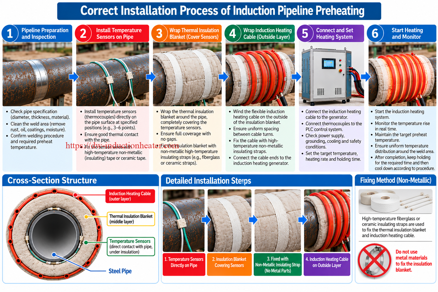
Step 1: Review the Approved Heat-Treatment Procedure
Confirm the material grade, applicable standard, required treatment temperature, heating rate, soaking period and cooling requirements.
Step 2: Inspect the Workpiece
Record the relevant dimensions, weld location, wall thickness and specified heating-zone width.
Check worksite conditions and confirm that the component is suitable for the planned heating process.
Step 3: Prepare Temperature Measurement Locations
Clean the workpiece surface at the approved thermocouple attachment positions.
Step 4: Attach Thermocouples Directly to the Steel
Install the specified K-type thermocouples directly against the metal surface.
Confirm reliable sensor attachment, calibration and channel identification.
Step 5: Wrap the Thermal Insulation Blankets
Cover the steel pipe and all installed thermocouple junctions with suitable thermal insulation blankets.
Ensure the required heating area is covered according to the approved procedure.
Step 6: Secure the Insulation Using Non-Metallic Straps
Use approved high-temperature, non-metallic insulating fabric straps to secure the thermal insulation blankets.
Do not use unapproved metallic bands or conductive fixing wire within the active induction-heating region.
Step 7: Wind the Induction Heating Cable
Install the flexible induction heating cable around the outside of the insulation blankets.
Maintain the specified number of turns and coil spacing.
Step 8: Connect the Generator and Temperature Sensors
Connect the induction coil and thermocouple leads to the appropriate equipment terminals.
Verify electrical supply, grounding, cooling and safety interlocks before heating.
Step 9: Program the Thermal Cycle
Configure the approved heating rate, treatment temperature, holding period and cooling requirements using the available equipment functions.
Step 10: Perform Controlled Heating
Energize the induction system and monitor the required metal temperature locations.
Confirm that temperatures remain within the specified process limits.
Step 11: Complete the Soaking Period
Maintain the required treatment temperature and prescribed holding time.
Evaluate all applicable measurement locations according to the qualified procedure.
Step 12: Perform Controlled Cooling
Complete the cooling stage in accordance with the approved heat-treatment requirements.
Step 13: Review and Retain Temperature Records
Check the recorded thermal cycle for compliance with the specified temperatures, rates and holding requirements.
Process Verification Checklist
| Inspection Item | Required Condition |
|---|---|
| Material | Correct grade and heat-treatment procedure |
| Thermocouples | Direct metal contact at specified positions |
| Thermal Insulation | Covers pipe and temperature sensors |
| Fixing Material | Approved non-metallic insulating straps |
| Induction Heating Cable | Installed outside the insulation |
| Electrical Connections | Correctly connected and inspected |
| Heating Program | Matches approved thermal procedure |
| Temperature Recording | Required channels operating correctly |
| Cooling | Follows approved cooling requirements |
Common Problems and Solutions
Induction stress-relief heat treatment requires reliable temperature measurement, correct induction coil installation and compliance with the approved thermal cycle.
Technical Troubleshooting Guide
| Problem | Possible Cause | Recommended Solution |
|---|---|---|
| Slow Heating | High thermal mass or inadequate useful thermal power | Review generator capacity, coil coupling and heating-zone dimensions |
| Nonuniform Temperature | Incorrect coil spacing, heat losses or workpiece geometry | Evaluate temperature distribution and coil arrangement |
| Incorrect Thermocouple Reading | Poor metal contact or incorrect sensor location | Reinstall sensors directly against the steel |
| Excessive Temperature Overshoot | Control response or power settings unsuitable for the process | Review thermal program and feedback response |
| Heating Cable Overheating | Incorrect load matching or installation | Stop operation and inspect the approved heating circuit |
| Metal Fixing Materials Become Hot | Unapproved conductive materials near the induction coil | Stop heating and remove unsuitable metallic fasteners |
| Generator Overheating | Insufficient cooling or excessive operating duty | Inspect cooling and confirm rated operating limits |
| Holding Temperature Cannot Be Maintained | Thermal losses exceed useful heating power | Evaluate insulation, generator capacity and zone arrangement |
| Insufficient Temperature Uniformity | Inadequate heating band or nonuniform heat conduction | Review the approved local heat-treatment arrangement |
| Incomplete Temperature Records | Recorder configuration or sensor problems | Check recording channels and data storage |
Preventive Maintenance Checklist
| Component | Inspection Requirement |
|---|---|
| Induction Generator | Inspect electrical and cooling systems |
| Induction Cable | Check insulation, terminations and mechanical damage |
| Output Connections | Inspect using approved de-energized maintenance procedures |
| Thermocouples | Check condition, attachment and calibration |
| Temperature Recorder | Verify channel identification and recording functions |
| Thermal Insulation | Check for deterioration and contamination |
| Non-Metallic Straps | Inspect thermal resistance and mechanical condition |
| Control System | Verify operating functions and fault indications |
Engineering Selection Guide
Stress-relief equipment selection begins with the workpiece mass, required thermal cycle, acceptable temperature gradients and heat losses.
Nominal generator output is not equal to useful thermal power absorbed by the selected workpiece region.
1. Calculate the Approximate Heated Metal Mass
For a cylindrical steel pipe, the mass of a selected axial heating band can be calculated using:
m = π × (D − t) × t × L × ρ
Where:
- m = heated steel mass, kg.
- D = pipe outside diameter, m.
- t = wall thickness, m.
- L = axial heating-band length, m.
- ρ = steel density, kg/m³.
2. Calculate the Sensible Heat Requirement
Q = m × Cp × ΔT
Where:
- Q = approximate sensible heat, kJ.
- m = selected heated mass, kg.
- Cp = average specific heat capacity, kJ/(kg·K).
- ΔT = target temperature minus initial temperature, K.
3. Engineering Example: Stress Relief Heating of a Steel Pipe
Consider the following hypothetical engineering calculation for a carbon-steel pipe heating band.
The selected example temperature is used for illustration only and does not establish an approved heat-treatment cycle for any specific steel grade.
| Engineering Parameter | Assumed Value |
|---|---|
| Pipe Outside Diameter | 323.9 mm |
| Wall Thickness | 12.7 mm |
| Axial Heating Band | 400 mm |
| Initial Temperature | 25°C |
| Illustrative Treatment Temperature | 620°C |
| Temperature Increase | 595 K |
| Assumed Steel Density | 7,850 kg/m³ |
| Assumed Average Specific Heat | 0.58 kJ/(kg·K) |
4. Calculate the Selected Pipe Mass
m = π × (0.3239 − 0.0127) × 0.0127 × 0.400 × 7850
m ≈ 38.99 kg
5. Calculate the Sensible Heat
Q = 38.99 × 0.58 × 595
Q ≈ 13,455 kJ
Converting into kilowatt-hours:
Q ≈ 3.74 kWh
This is the approximate sensible heat required to raise the selected pipe-band volume from 25°C to 620°C under the stated assumptions.
It does not represent the actual electrical energy consumed by the induction heating generator.
6. Theoretical Heating Time at Different Useful Power Levels
If average useful thermal power absorbed by the selected workpiece volume is known:
Heating Time = Required Thermal Energy / Useful Thermal Power
| Assumed Useful Thermal Power | Idealized Heating Time |
|---|---|
| 4 kW | 56.06 minutes |
| 6 kW | 37.37 minutes |
| 8 kW | 28.03 minutes |
| 10 kW | 22.42 minutes |
| 12 kW | 18.69 minutes |
| 15 kW | 14.95 minutes |
| 20 kW | 11.21 minutes |
Engineering clarification: These heating times are idealized energy calculations, not recommended heating rates and not measured performance of a specific MYD machine.
Actual stress-relief heating time is often governed by the maximum permitted heating rate and temperature gradient rather than the minimum theoretical heating time.
7. Heating Time Versus Qualified Heating Rate
Suppose the approved procedure permitted a heating rate of 100°C/hour from 25°C to 620°C.
The corresponding heating time would be:
Heating Time = (620 − 25) / 100 = 5.95 hours
This shows why an induction generator may have sufficient instantaneous heating power while the actual heat-treatment operation still requires several hours.
In this example, the required heating duration is controlled by the assumed ramp rate, not by the shortest possible energy-delivery time.
The 100°C/hour value is a hypothetical calculation parameter, not a universal PWHT recommendation.
8. Holding Power and Thermal Losses
During the soaking period, the workpiece temperature must remain within the specified range.
Even after the target temperature has been reached, additional electrical power may be required to replace heat lost through radiation, convection and conduction into adjacent metal.
Consequently, the total process energy may be much higher than the sensible heat calculated for the selected heating band.
9. Important Factors in PWHT Equipment Sizing
| Engineering Factor | Effect on Selection |
|---|---|
| Material Grade | Determines permissible temperature and thermal cycle |
| Pipe Diameter | Influences coil length and heating arrangement |
| Wall Thickness | Affects heated mass and through-wall temperature distribution |
| Heating Band Width | Determines initial selected heated volume |
| Maximum Heating Rate | Limits permitted ramp speed |
| Holding Temperature | Determines treatment conditions and heat losses |
| Holding Time | Determines sustained operation requirements |
| Temperature Uniformity | Determines sensor locations and possibly multiple zones |
| Thermal Insulation | Influences energy losses |
| Continuous Operating Duty | Determines generator cooling and sustained output requirements |
10. Local Stress Relief Versus Full-Furnace Heat Treatment
| Comparison | Localized Induction Heating | Full-Furnace Heat Treatment |
|---|---|---|
| Heating Region | Selected component zone | Complete component or large assembly |
| Heating Equipment | Induction generator and work coil | Industrial heat-treatment furnace |
| Temperature Distribution | Depends on coil, insulation and adjacent geometry | Depends on furnace design and workpiece loading |
| Local Temperature Gradients | Require careful evaluation | Different gradient conditions and thermal response |
| Site Applications | Possible when approved and accessible | Usually requires movement to a furnace |
| Process Compliance | Requires qualified local-treatment procedure | Requires qualified furnace-treatment procedure |
Advantages and Limitations
Main Advantages
1. Localized Metal Heating
Induction heating can supply heat to selected conductive metal regions without placing the entire component inside a furnace.
2. Flexible Heating Coil Arrangements
Suitable flexible induction cables can be arranged around accessible cylindrical workpieces and selected irregular geometries.
3. Temperature Monitoring
Multi-point thermocouple measurement allows selected metal temperatures to be monitored during the process.
4. Programmable Heating Functions
Compatible control configurations may support programmed temperature changes, holding periods and recording functions.
5. No Combustion Flame Required
Induction heating does not require an open combustion flame as the primary heating source.
Nevertheless, industrial electrical safety, hot surfaces and surrounding combustible materials must still be controlled.
6. Industrial Field Applications
Induction equipment can be evaluated for approved localized heat-treatment operations where access to a full-size industrial furnace is impractical.
Technical Limitations
| Limitation | Engineering Explanation | Recommended Action |
|---|---|---|
| Material Restrictions | Incorrect treatment temperatures may damage mechanical properties | Use approved material-specific procedures |
| Local Temperature Gradients | Only a selected region is directly heated | Verify permitted local treatment arrangement |
| Residual Stress Distribution | Local heating does not guarantee complete stress removal | Evaluate the metallurgical and structural objective |
| Temperature Control Capability | Historical published tolerance lacks test conditions | Verify actual measured performance |
| Generator Continuous Duty | Long soaking periods require sustained operation | Confirm cooling and rated output conditions |
| Electrical Input Data | Published currents conflict with nominal output ratings | Confirm current factory electrical specifications |
| PWHT Compliance | Equipment features alone do not establish compliance | Follow qualified procedures and retain records |
Why Choose HLQ?
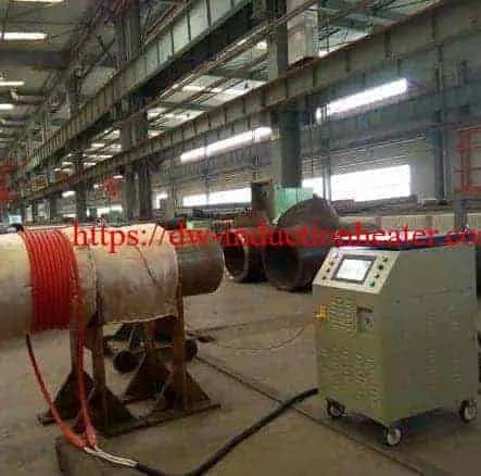
HLQ Induction Equipment Co., Ltd. supplies industrial induction heating systems for metal processing, welding preparation, localized heat treatment and related industrial applications.
Industrial MYD Power Range
The published MYD series provides nominal output ratings from 40 kW to 120 kW, allowing different equipment sizes to be evaluated for industrial heating requirements.
IGBT Induction Power Conversion
IGBT-based generators provide high-frequency electrical power for compatible induction heating coils.
Flexible Induction Heating Solutions
Compatible flexible heating cables allow suitable coil arrangements around steel pipes and selected fabricated components.
PLC Temperature Control
Published MYD system features include PLC touchscreen operation and multi-point temperature monitoring.
Temperature Recording Options
Selected configurations can include digital temperature recorders and associated recording accessories.
Application-Specific Equipment Selection
Equipment selection should consider the workpiece material, thickness, dimensions, target temperature, required thermal cycle, temperature measurement locations and sustained heating requirements.
For additional application information, see HLQ induction pipeline heating systems and induction welding preheating systems.
Specific post-welding applications are also discussed in HLQ post-welding stress relieving equipment resources.
10 Core FAQs
1. What Is Induction Stress Relief Heat Treatment?
Induction stress relief heat treatment uses electromagnetic induction to heat suitable conductive metal components according to a controlled thermal cycle intended to reduce selected residual stresses. The actual treatment temperature and duration depend on material and process requirements.
2. What Is the Difference Between Stress Relief and PWHT?
Stress relief is one possible objective of post-weld heat treatment. PWHT refers more broadly to thermal treatments performed after welding under specified conditions and may have different metallurgical purposes.
3. What Power Ratings Are Available in the HLQ MYD Series?
The audited HLQ product page lists six nominal output ratings: 40 kW, 50 kW, 60 kW, 80 kW, 100 kW and 120 kW.
4. What Temperature Is Required for Stress Relief Heat Treatment?
There is no universal temperature suitable for all steels. The required temperature depends on steel grade, original heat-treatment condition, thickness, mechanical property requirements and applicable heat-treatment procedure.
5. Can Induction Heating Be Used for Pipeline Weld Stress Relief?
Yes, when the material and applicable procedure permit localized induction heat treatment. The heating arrangement must provide the required temperature distribution, heating rate, holding time and controlled cooling.
6. Where Should Thermocouples Be Installed?
Thermocouple junctions should contact the steel pipe directly at the specified measurement positions. Thermal insulation blankets cover both the pipe and the sensors, while the flexible induction heating cable is installed around the outside of the insulation.
7. Can Metallic Straps Be Used to Secure Insulation?
Unapproved metallic fixing bands or steel wire should not be used in the energized induction heating zone. Suitable non-metallic, high-temperature insulating straps should be used according to the approved installation requirements.
8. Does the MYD Series Provide Six Independent Temperature-Control Zones?
The original page describes six-channel temperature-monitoring capability. This does not necessarily establish six independent heating zones. The number of control outputs, feedback channels and available temperature programs must be confirmed for the selected configuration.
9. How Much Electrical Power Is Required for Stress Relief Heat Treatment?
The required power depends on the workpiece mass, treatment temperature, heating-rate limit, heat losses, insulation, coil coupling and holding duration. A thermal calculation and verification of the generator’s sustained output capability are required for reliable equipment selection.
10. Can Induction Stress Relief Completely Eliminate Residual Stresses?
No general process can guarantee complete elimination of every residual stress. The degree and distribution of stress reduction depend on the material, workpiece geometry, restraint and thermal treatment. Localized heating may also produce temperature gradients that require engineering evaluation.
Technical Data and Engineering Notice
The MYD technical specifications presented on this page are based on historical manufacturer-published information.
Published input current, continuous output power, temperature-control tolerance, cooling configuration and environmental limits require confirmation against current factory specifications.
All engineering calculations and thermal-cycle examples are illustrative and do not represent measured customer production results.
Actual stress-relief and post-weld heat-treatment operations must comply with the relevant material requirements, approved heating procedure, equipment instructions and applicable safety standards.
HLQ-Induction-Stress-Relief-Heat-Treatment-Brochure