Induction Preheating Steel Bar
Steel Bar Induction Preheating for U-Bolt Forming
Quick Answer
Steel bar induction preheating prepares a straight round blank for forming in a U-bolt die. The application reference configuration specifies DW-MF-90kW equipment at 20 kHz, a fifteen-turn helical coil with a ceramic insert, and a 0.795 in (20.19 mm) diameter, 15 in (381 mm) long steel blank. The reference target is approximately 1500°F (816°C), with a heating interval of 9.90 seconds. The final recipe depends on steel grade, coil coupling, temperature distribution and transfer conditions.
Table of Contents
- What is the Steel Bar Induction Preheating System?
- Key Applications
- Suitable Materials
- Working Principle
- Technical Specifications
- Recommended Model Selection
- Process Workflow
- Common Problems and Solutions
- Engineering Selection Guide
- Advantages and Limitations
- Why Choose HLQ?
- 10 Core FAQs
What is the Steel Bar Induction Preheating System?
This application combines an induction power supply, a remote workhead, a helical coil with a ceramic insert and a fixture for the straight steel blank. After heating, the bar is transferred to a die and formed into a U-bolt. Heating conditions and die-entry temperature must suit the actual steel and forming operation.
The application reference uses the DW-MF-90kW designation and a 20 kHz operating point within the family of medium frequency induction heating systems. Select the installed power, tuning capability, cooling and controls to suit the actual workpiece and production schedule.
Key Applications
| Application | Heating task | Process considerations |
|---|---|---|
| U-bolt blank preheating | Heat the straight round steel blank before die forming | Match the thermal profile and die-entry temperature to the steel and forming operation |
| Related round-bar bending or forming | Develop a suitable temperature profile for the required deformation | Qualify the material, coil, fixture and forming recipe for the selected part |
| Different U-bolt sizes | Match the heated diameter and length to a different blank | Requires new thermal-load, clearance, transfer and die-entry checks |
| Integrated heating and forming cells | Coordinate heating, verification, transfer and die operation | Select handling and control functions for the required production sequence |
The wider process family is induction forging and hot forming. Choose the forming temperature according to the steel grade and manufacturing procedure.

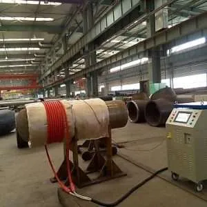
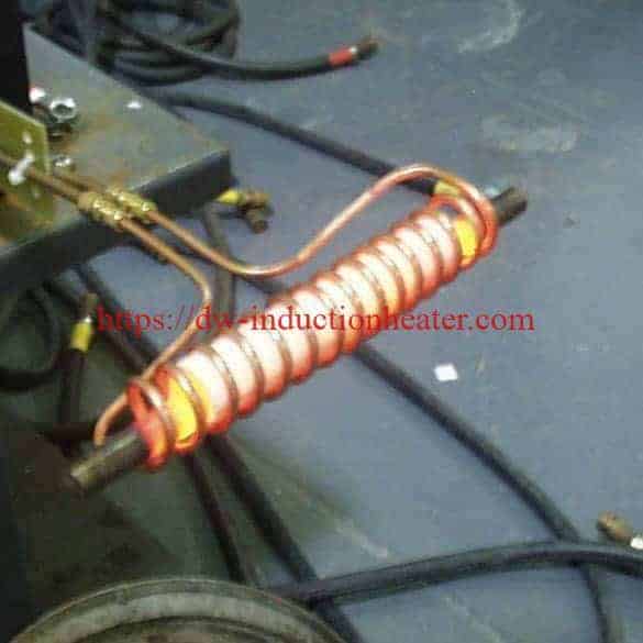
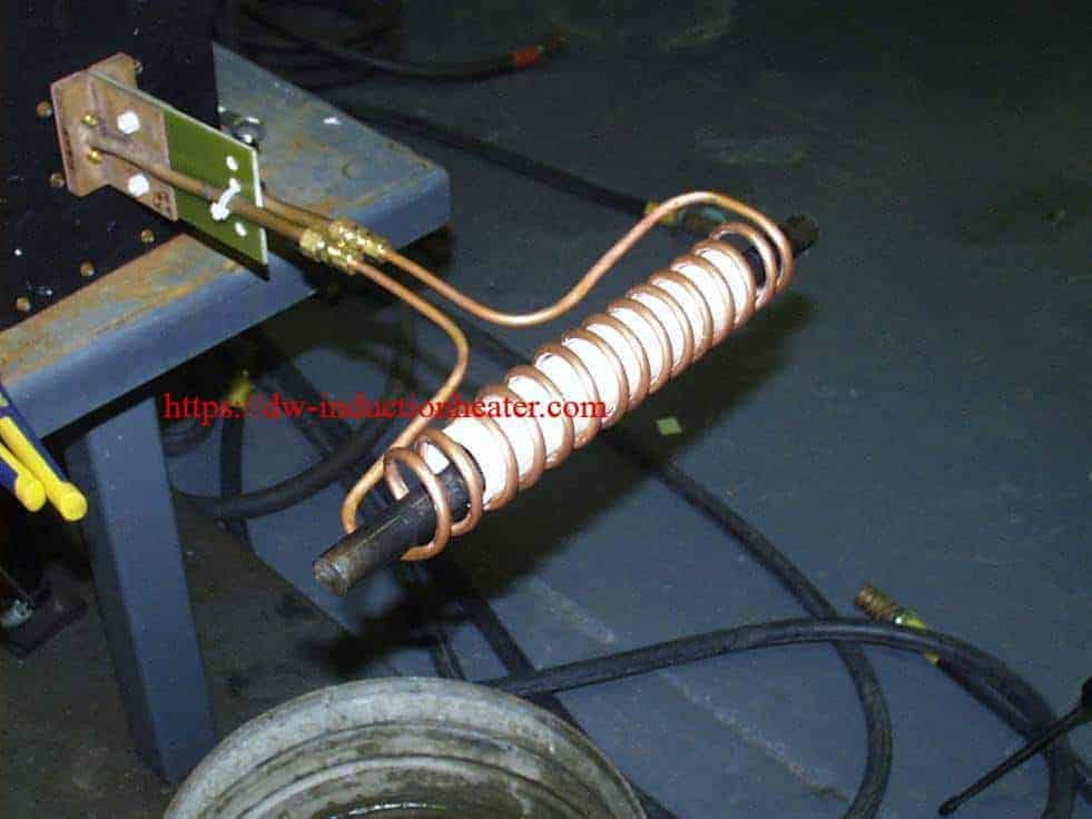
Steel Bar Heating Setup
Suitable Materials
Select the heating and forming recipe using the steel grade, chemistry, initial condition and required properties after forming. Review coatings and surface treatments before applying a high-temperature cycle.
| Material or condition | Application status | Required review |
|---|---|---|
| Round steel bar stock | Reference workpiece family | Confirm the grade, drawing, initial condition and forming acceptance requirements |
| Carbon and low-alloy steels | Potential candidates after application qualification | Grade-specific forming window, thermal profile and post-form properties |
| Already heat-treated steel | Requires assessment before reheating | Changes to hardness, microstructure and final mechanical requirements |
| Coated or surface-treated bars | Separate surface-condition review | Coating temperature limits, surface reactions and temperature-measurement effects |
| Stainless and high-alloy steels | Separate heating and forming development | Electrical coupling, forming temperature, surface quality and atmosphere requirements |
| Nonferrous blanks | Requires a separate material-specific recipe | A material-specific power, frequency, coil and forming assessment |
Working Principle
Alternating current in the helical coil generates a changing magnetic field. Currents induced in the conductive steel produce resistive heat, and thermal conduction redistributes that heat within the bar. The electrical load changes as the steel heats because its electrical and magnetic properties change with temperature.
The ceramic insert sits within the coil assembly and provides a nonmetallic interface around the workpiece. Select its material, bore, wall thickness, support arrangement and contact conditions to suit the coil design and loading method.
The principles of induction heating explain the energy transfer. Application-specific helical induction heating coils determine how the field is presented along the blank.

| Component | Reference configuration | Engineering role or limit |
|---|---|---|
| Power supply | DW-MF-90kW application reference | Confirm installed electrical ratings and the operating power required by the thermal load |
| Remote workhead | Eight 1.0 μF capacitors; stated total 2.0 μF | Part of the resonant matching circuit; use the approved equipment circuit and matching procedure |
| Helical coil | Fifteen turns | Couples electromagnetic energy into the bar along the heating region |
| Ceramic insert | Ceramic insert within the coil | Construction and service limits require the coil specification |
| Workpiece fixture | Part-specific locating and support arrangement | Must maintain repeatable location, support and extraction |
| Temperature verification | Measurement method selected for the thermal acceptance requirements | Required to qualify surface, axial and core-temperature acceptance |
Technical Specifications
| Parameter | Reference value | Interpretation |
|---|---|---|
| Application | Preheat round steel bar stock before forming a U-bolt | The heated blank is placed in a die for forming |
| Equipment designation | DW-MF-90kW | Application reference model; final selection depends on the actual thermal task |
| Bar diameter | 0.795 in (20.19 mm) | Nominal reference dimensions |
| Bar length | 15 in (381 mm) | Reference blank length and full-length heating target |
| Target temperature | 1500°F (approximately 816°C) | Reference target; select the final temperature window for the actual steel |
| Operating frequency | 20 kHz | Application operating point; confirm the available tuning range for the selected equipment |
| Heating interval | 9.90 seconds | Reference power-application interval; loading, transfer and forming add to total cycle time |
| Remote workhead capacitors | Eight units of 1.0 μF; stated total 2.0 μF | Equivalent network value; follow the approved workhead circuit |
| Heating coil | Fifteen-turn helical coil with ceramic insert | Application-specific construction |
| Following operation | Die forming into a U-bolt | Define transfer allowance, bend geometry, die requirements and subsequent operations in the manufacturing plan |
| Steel grade | Project-specific | Specify the material certificate and final property requirements |
| Utilities, duty and control | Project-specific | Input service, cooling, continuous rating, temperature tolerance and closed-loop features require equipment-specific confirmation |
Calculated Reference Values
| Quantity | Basis | Calculated reference |
|---|---|---|
| Diameter conversion | 0.795 × 25.4 | 20.193 mm, approximately 20.19 mm |
| Length conversion | 15 × 25.4 | 381 mm |
| Temperature conversion | (1500 − 32) × 5/9 | 815.56°C, approximately 816°C |
| Nominal bar cross-section | π × 20.19² / 4 | Approximately 320.16 mm² |
| Nominal solid-cylinder volume | π × 20.19² × 381 / 4 | Approximately 121.98 cm³; based on nominal unexpanded dimensions |
| Heating-only step frequency | 60/9.90 and 3600/9.90 | 6.06 steps/min or 363.64 steps/h with zero additional time |
The calculated step frequency is not measured production output. Any conversion to pieces per hour additionally requires a known loading count, handling sequence, forming cycle, availability and yield.
Recommended Model Selection
Evaluate the DW-MF-90kW application reference against the actual steel blank, thermal load, forming window and production schedule. Confirm the selected equipment and recipe with representative parts.
| Requirement | Selection direction | Validation needed |
|---|---|---|
| Reference 20.19 mm × 381 mm U-bolt blank | Evaluate the reference equipment with a matched coil, ceramic insert and representative steel blank | Selected electrical ratings, operating settings, material identity and temperature results |
| Similar diameter and length | Evaluate a matched helical coil and ceramic-insert arrangement | Axial and core-temperature behavior, part location and transfer window |
| Larger diameter or heated length | Recalculate the thermal load and review frequency, power and coil together | Surface-to-core gradients, heat losses and sustainable heating time |
| Shorter line takt | Assess loading, heating, verification, transfer and forming as a complete cell | Bottleneck, equipment duty, cooling and sustained good-part output |
| Several bar sizes | Use validated coil, insert, fixture and recipe combinations | Changeover, rematching and first-part acceptance |
The wider range of induction bar and billet heaters should be selected against the actual thermal task. A larger model number alone does not establish a suitable temperature profile or production rate.
Process Workflow
- Confirm material and drawing. Establish the steel grade, initial condition, blank dimensions and required U-bolt properties.
- Prepare the heating assembly. Confirm the matched coil, ceramic insert, workhead, fixture and utility requirements.
- Define temperature verification. Select measurement locations and a qualified method for the surface, axial profile and required core behavior.
- Load and heat the blank. Maintain repeatable position and apply the qualified recipe. Use the reference heating interval as a starting point for a qualified part-specific recipe.
- Verify and transfer to the die. Control the delay and confirm the required temperature at forming entry.
- Form and inspect. Check bend geometry, dimensions, surface condition and material requirements under the approved manufacturing plan.

Common Problems and Solutions
| Problem | Possible contributors | Engineering response |
|---|---|---|
| Hot surface with an underheated center | Unsuitable power-time profile, coupling or insufficient heat redistribution | Validate the core requirement and review frequency, coil geometry and the heating profile |
| Uneven temperature along the blank | Coil end effects, insertion variation, support contact or local heat loss | Check both ends and intermediate locations; refine location, support and coil profile |
| Heating varies between parts | Material, diameter, initial temperature, actual power, matching or cooling variation | Control incoming blanks and record process conditions; inspect the fixture and utilities |
| Ceramic insert is worn or damaged | Repeated loading contact, incorrect alignment or unsuitable service conditions | Inspect against the coil specification, correct handling and restore the approved insert arrangement |
| Optical readings appear inconsistent | Emissivity, scale, reflections, spot size or viewing restrictions | Qualify the sensor settings and sightline against a suitable reference method |
| Bar cools before die forming | Long transfer, handling delays or heat extraction by tools and supports | Qualify the transfer window and verify temperature at die entry |
| Scale or surface deterioration | Exposure time, atmosphere, surface condition or an unsuitable recipe | Review the thermal cycle and surface requirements; compare results using the actual material |
| Inconsistent U-bolt geometry | Blank variation, thermal gradients, die setup or timing variation | Review the heating and forming process together and measure the required finished dimensions |
Engineering Selection Guide
| Input | Required information | Why it matters |
|---|---|---|
| Material | Grade, initial condition, coating and final property requirements | Defines the forming window and permitted thermal exposure |
| Blank geometry | Actual diameter, length, tolerances and required heated region | Defines the coil envelope, clearance and participating thermal mass |
| Thermal acceptance | Initial temperature, target range, axial variation and core requirement | Defines what the heating system must achieve and how it is verified |
| Forming operation | Die-entry window, transfer delay, bend geometry and acceptance criteria | Links heating to the actual U-bolt result |
| Production | Loading count, handling, heating, transfer, forming and changeovers | Defines sustained output and equipment duty |
| Utilities | Electrical service, cooling and installation conditions | Defines compatibility and continuous operating capability |
Thermal and Cycle Calculations
| Quantity | Relationship | Boundary |
|---|---|---|
| Workpiece thermal energy | Q = m × [h(Ttarget) − h(Tinitial)] | Use actual participating mass and grade-appropriate enthalpy, including transformations where relevant |
| Average absorbed power | Pabsorbed,avg = (Q + Qloss) / theating | Requires actual losses and thermal boundary; it is not the model-name power |
| Sequential station cycle | tcycle = tload + theat + tverify + ttransfer + tform + tunload | Applies to sequential operations; overlapping cells require bottleneck analysis |
| Good-part production rate | Depends on parts per cycle, cycle time, availability and yield | Cannot be inferred from the 9.90-second heating interval alone |
Determine energy consumption from measured input power and the complete operating cycle. Confirm production capacity through a sustained run that includes handling, forming, changeovers and good-part yield.
Workhead Capacitance
The application reference specifies eight 1.0 μF capacitors with a 2.0 μF equivalent total. This is possible with a suitable series/parallel network. For example, four parallel branches, each containing two 1.0 μF capacitors in series, would give 4 × 0.5 μF = 2.0 μF. This example explains the equivalent value; use the approved circuit for the selected workhead.

Advantages and Limitations
| Potential advantage | Condition or limitation |
|---|---|
| Heating aligned with the blank geometry | Requires a matched coil, insert and fixture for the actual diameter and length |
| Short reference heating interval | The 9.90-second heating reference must be qualified for the actual part and excludes handling and forming |
| Potential through-heating capability | Uniformity must be demonstrated at the required axial and core locations |
| Reduced high-temperature residence | May reduce oxidation exposure compared with a longer process, but scale depends on material, time, atmosphere and surface condition |
| Repeatable process settings | Requires control of material, position, matching, actual power, cooling and transfer |
| Integration with die forming | Handling, temperature verification and die coordination must be engineered for the selected cell |
Define the acceptable temperature variation, surface condition and forming result before production release. Compare energy use and scale formation under the actual operating conditions. Verify through-heating with measurements suited to the axial and core-temperature requirements.
Why Choose HLQ?
HLQ Induction Equipment offers induction power-supply manufacturing, custom coil design, process engineering, cooling-system matching and automation integration. These disciplines are relevant to developing a bar-heating and U-bolt-forming cell.
For this application, useful custom induction heating solutions combine the bar specification, matched coil and ceramic insert, fixture, utilities, thermal verification and forming transfer window. Configuration-specific features and guarantees should be supported by an identified equipment specification and an actual trial record.
Related Induction Heating Applications
Explore related heating applications. Each process requires its own material, coil and temperature recipe.
- Induction Preheating Blades and Knives
- Induction Pipe and Tube Heating Applications
- Induction Preheating Before Welding for Oil and Gas Pipelines
- Induction Preheating for Steel Rivets and Handrail Bars
- Induction Preheat Welding Steel Rods
- Induction Preheating Steel Tube for Welding
10 Core FAQs
1. What is the purpose of steel bar induction preheating here?
The application heats a straight round steel blank before it is placed in a die and formed into a U-bolt.
2. Which equipment and frequency are listed for this application?
The application reference lists DW-MF-90kW equipment and a 20 kHz operating point. Confirm the final equipment specification and operating recipe for the actual workpiece.
3. What bar dimensions are used in the application reference?
The reference blank is 0.795 in, approximately 20.19 mm, in diameter and 15 in, or 381 mm, long. Specify production tolerances on the part drawing.
4. Is the forming temperature 1500°F or 816°C?
They are rounded equivalents: 1500°F converts to approximately 815.56°C. The reference temperature is rounded to 816°C. The correct temperature for another part depends on its steel and forming procedure.
5. Does 9.90 seconds describe the complete production cycle?
No. It is the reference power-application interval. Loading, checking, transfer, forming, unloading and equipment availability also affect output.
6. What coil is described?
A fifteen-turn helical coil with a ceramic insert is the reference arrangement. Select bore, length, pitch, clearance and insert construction to suit the blank and handling method.
7. Can eight 1.0 μF capacitors produce a 2.0 μF total?
Yes. An appropriate series/parallel network can produce a 2.0 μF equivalent value from eight 1.0 μF units. The approved equipment circuit determines the actual connection.
8. How is through-heating uniformity verified?
Set the allowable axial and surface-to-core temperature variation, then validate it using qualified measurement locations and methods. A surface glow alone does not establish a uniform core temperature.
9. Can the same recipe be used for another steel grade or blank size?
It must be requalified. Material properties, diameter, heated length, coil coupling, losses and the forming window can change the required recipe.
10. What evidence is needed before production release?
Identify the actual equipment and material, record operating settings and temperature results, confirm the transfer window, inspect the formed U-bolt and demonstrate the required sustained cycle.