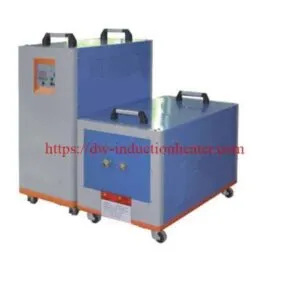
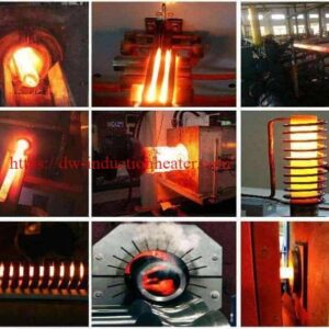
IGBT induction heating machine
IGBT Induction Heating Machine: Medium Frequency, High Frequency and Ultra-High Frequency Power Supplies from 6 kW to 160 kW
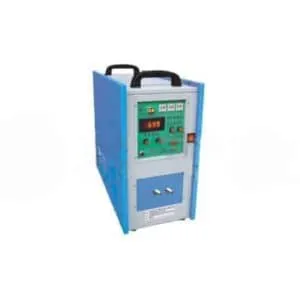
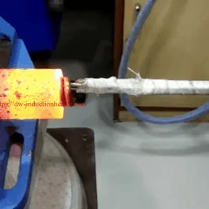
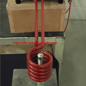
An IGBT induction heating machine is the power supply at the centre of an induction heating system. It takes three-phase mains electricity, rectifies it, and uses IGBT inverter devices to convert it into a controlled medium, high or ultra-high frequency alternating current. That current flows through a water-cooled copper coil, the coil produces a changing magnetic field, and the field induces eddy currents inside the workpiece. The resistance of the metal turns those currents into heat, inside the metal itself.
This page is the range reference for the whole HLQ IGBT programme. It carries the published model tables for the medium frequency, high frequency and ultra-high frequency series in one place, sets out how the frequency band decides how deeply the heat goes, and shows which published power class covers which published application. The medium frequency entry point in the range is the medium frequency induction generator, the largest machine in that ladder being the DW-MF-160 at 160 kW.

Quick Answer
The HLQ IGBT induction heating programme is published in three frequency bands, each with its own model ladder and its own heating depth. Medium frequency (DW-MF) covers 15 kW to 160 kW at 1 kHz – 20 kHz for deep and through heating. High frequency (DW-HF) covers 15 kVA to 120 kVA at 30 kHz – 80 kHz for surface hardening and brazing. Ultra-high frequency (DW-UHF) covers 6.0 kW to 60 kW at 50 kHz – 2 MHz for small parts and thin-wall brazing.
IGBT induction heating machine — the key published figures at a glance
| Parameter | Published value |
|---|---|
| Inverter technology | IGBT solid-state inverter |
| Medium frequency series | DW-MF-15 to DW-MF-160, 8 models |
| Medium frequency input power | 15 kW – 160 kW |
| Medium frequency input current | 23 A – 240 A |
| Medium frequency oscillation frequency | 1 kHz – 20 kHz, normally about 4, 8, 11, 15 or 20 kHz according to the application |
| Medium frequency supply | 3-phase, 380 V ± 10 % |
| High frequency series | DW-HF-15 Series to DW-HF-120 Series, 8 models |
| High frequency rated power | 15 kVA – 120 kVA |
| High frequency oscillation frequency | 30 kHz – 80 kHz |
| Ultra-high frequency series | DW-UHF-6.0KW-I to DW-UHF-60KW, 8 models |
| Ultra-high frequency rated power | 6.0 kW – 60 kW |
| Ultra-high frequency oscillation frequency | 1.1 MHz – 2 MHz down to 50 kHz – 150 kHz across the series |
| Published output voltage | 70 – 550 V |
| Published duty cycle | 100 %, 24 hours work (HF DW-HF-15 Series is published at 80 %) |
| Published operating mode | Constant current or constant power, with soft-switching, resonance dual control and frequency tracking |
| Published protection set | Over-voltage, over-current, over-heat, phase loss and water shortage alarms with automatic control and protection |
| Cooling | Water cooling for the coil, the power supply, the capacitors and the cables |
| Published installation | Connect to 3-phase 380 VAC and cooling water only |
For the physical background, see the HLQ induction heating principle page.
Table of Contents
- Quick Answer
- What is the IGBT Induction Heating Machine?
- Key Applications
- Suitable Materials
- Working Principle
- Technical Specifications
- Recommended Model Selection
- Process Workflow
- Common Problems and Solutions
- Engineering Selection Guide
- Advantages and Limitations
- Why Choose HLQ?
- 6 Core FAQs
What is the IGBT Induction Heating Machine?
An IGBT induction heating machine is a solid-state power supply. There is no vacuum tube, no thyristor stack and no combustion. The name IGBT refers to the insulated gate bipolar transistors at the output stage: switchable semiconductor devices that are turned on and off at the carrier frequency to shape the output waveform. HLQ publishes this technology across the medium frequency, high frequency and ultra-high frequency bands, and states that the medium frequency generator uses a parallel oscillating circuit, which gives the series its load adaptability and its ability to hold 100 % duty.
It is worth separating three things that buyers often conflate, because the published HLQ pages use all three terms:
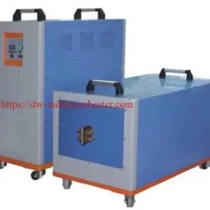
- The generator is the power supply alone: the IGBT inverter cabinet, the capacitor cabinet, the control panel and the cooling circuit. The published main parts of a medium frequency system are the induction heating generator, the melting or heating furnace and the compensation capacitor.
- The transformer and the coil are the heating head. The generator converts electricity into high-frequency alternating current; the transformer matches that output to the load; the coil produces the field that heats the part. A generator on its own heats nothing.
- The complete machine is generator, transformer, coil, cooling and control specified as one system. The published split-type arrangement separates the generator from the heating head so the head can sit at the production line while the generator sits elsewhere in the workshop.
The frequency band is the single decision that shapes everything else, because frequency sets the heating depth. The higher the frequency, the shallower the current penetrates and the more localised the heating becomes. Medium frequency heats deep into the part; high frequency concentrates on the surface; ultra-high frequency works on small, thin or delicate parts. Everything else — the power, the coil, the transformer, the cooling — follows from that choice.

The published bands and what they are for
| Frequency type | Published frequency range | Published common application |
|---|---|---|
| KGPS Medium Frequency | 0.1 – 10 kHz | Melting furnace, large steel heating |
| Medium Frequency | 0.2 – 20 kHz | Forging, melting, deep heating |
| Super Audio Frequency | 20 – 50 kHz | Medium-depth hardening, brazing |
| High Frequency | 30 – 80 kHz | Surface hardening, brazing |
| Ultra High Frequency | 50 kHz – 2 MHz | Small parts, thin surface heating |
Key Applications
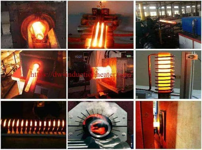
The published main applications for the HLQ IGBT induction heating machines are penetration heating occasions — rod heating for forging and rod end heating — melting of almost all kinds of metals, heating of stators or rotors for fitting, heating of tube ends for extrusion, and heating of moulds, deep quenching of shafts and gears, tempering or preheating of weld joints.
Broken down by process, the published range covers:
| Process | What the machine does | Typical parts |
|---|---|---|
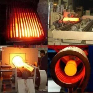
| Forging and billet heating | Heats the billet to forming temperature before it goes to the press; fast heating, less oxidation, better temperature uniformity, easy automatic feeding | Steel bar forging, fastener production, bearing rings, automotive parts, hand tools, copper and brass billet heating |
| Surface hardening | Heats the surface of steel parts quickly, followed by immediate quenching, to improve surface hardness, wear resistance and fatigue strength | Shafts, gears, sprockets, pins, rails, crankshafts, camshafts |
| Brazing | Joins metal parts using a filler metal — clean, fast and repeatable | Copper tube brazing, carbide tool brazing, HVAC pipe joints, brass fittings, automotive parts, heat exchanger components |
| Melting | Melts metal inside a crucible, electromagnetically stirred, then poured | Cast iron, steel, stainless steel, copper, brass, aluminium, gold and silver |
| Annealing | Softens metal, relieves stress and improves ductility | Stainless steel tube, copper wire, steel strip, weld seam, aluminium parts |
| Shrink fitting | Expands a component so it can be assembled onto a shaft | Bearings, gears, motor rotors |
For the rod and billet duty specifically, the published route is set out on the induction billet heater for steel, titanium and brass page, and the brazing duty on the induction brazing machine for copper, brass, carbide and HVAC brazing page. Small precision brazing work is handled at the other end of the range, where HLQ publishes the ultra high frequency induction brazing system.

The four paths above are the same machine doing four different jobs. What changes between them is the band, the power class and the coil, and the temperature and cycle time the part has to reach. Which band a job needs is decided by how deep the heat has to go, not by the size of the machine.

Suitable Materials
Induction heating works best on electrically conductive materials, and how well a material heats depends on two of its properties at once: electrical resistivity and magnetic permeability. That is why steel heats faster than copper in most induction applications — steel has higher electrical resistance and is magnetic, while copper has very low resistance and needs higher current, better coil coupling or a different frequency selection to heat at a useful rate.
| Material | Published induction heating suitability |
|---|---|
| Carbon steel | Excellent |
| Cast iron | Excellent |
| Stainless steel | Good |
| Copper | Good, but needs suitable design |
| Brass | Good |
| Aluminum | Good, but requires higher current/power |
| Titanium | Good |
| Nickel alloy | Good |
| Graphite | Excellent in some furnace applications |
| Plastic | Not directly heated unless combined with metal susceptor |
| Glass | Not directly heated unless using conductive coating or susceptor |
Two further points matter when the workpiece is steel. Above the Curie temperature — approximately 770 °C for steel — the steel loses most of its magnetic properties and the hysteresis contribution to heating disappears, so heating continues on eddy current heating alone. And in magnetic materials a second heating effect is available: when the magnetic domains repeatedly change direction with the field, the internal magnetic friction produces additional heat, in addition to the eddy current effect.
Non-conductive materials cannot be heated directly at all, but they can be heated indirectly through a metal or graphite susceptor placed between the coil and the part.

Working Principle
The heating sequence is the same for every band; only the frequency and the power change. HLQ publishes it as a chain: AC power supply → frequency converter or induction heating generator → alternating current to the copper coil → alternating magnetic field around the coil → eddy currents generated in the metal workpiece → electrical resistance produces heat → fast, clean, controlled heating.
In mechanical detail, the power supply converts standard electricity into medium-frequency, high-frequency or ultra-high-frequency alternating current through an internal rectifier and filter circuit and then an IGBT inverter bridge. On the medium frequency series HLQ publishes the specific control features: soft-switching resonance dual-control and frequency tracking, a wide frequency range with automatic tracking so that no adjustment is needed at the scene, and constant output voltage or constant power control modes as alternatives. The display shows output power, output frequency, output voltage and current.
Four consequences follow from the mechanism, and they explain most of the operating behaviour of an induction heating machine:
- The heat is made inside the metal. The coil does not touch the workpiece and the coil itself does not get hot. Nothing is transferred across a refractory wall and no combustion gas ever reaches the part.
- Only the skin is heated directly. The induced current concentrates near the surface, so the frequency decides how deep the heat goes and how quickly it spreads by conduction into the core.
- The temperature is set electrically. There is no flame to modulate, so the control loop is the power supply itself: constant current or constant power, with a timer that can be preset and adjusted to control the heating curve and the heating temperature.
- The protection is electrical and fluidic. The published alarm set covers over-voltage, over-current, over-heat, phase loss and water shortage, with automatic control and protection and real-time display of the working parameters.
The background physics, including the frequency bands, the skin effect and the two heating effects, is set out on the HLQ induction heating principle page, and the full published brochure is available as the HLQ induction heating brochure. HLQ’s own technical note on the subject sets out the skin and proximity effects and defines penetration depth as the point where the RF current falls to about 37 % of its surface value; it is published as the HLQ induction heating principle technical paper.
The band that matters for surface work is the high frequency end of the range. HLQ publishes it separately as the high frequency induction heating equipment, where the same chain is driven at 30 – 80 kHz through a separate high-frequency transformer and a resonant matching circuit rather than the medium frequency parallel oscillating circuit.

Read the diagram from the left. The supply is rectified, inverted by the IGBT bridge and matched through the parallel oscillating circuit and its capacitor bank to the transformer and coil. The field induces eddy currents that circulate in a thin skin at the surface of the workpiece, and the resistance of the metal turns those currents into heat inside the part. On the right, the three bands are compared on the only axis that matters commercially: how deep the heat goes.
Technical Specifications
1. DW-MF medium frequency series
| Specification | DW-MF-15 | DW-MF-25 | DW-MF-35 | DW-MF-45 | DW-MF-70 | DW-MF-90 | DW-MF-110 | DW-MF-160 |
|---|---|---|---|---|---|---|---|---|
| Input power max | 15 kW | 25 kW | 35 kW | 45 kW | 70 kW | 90 kW | 110 kW | 160 kW |
| Output voltage | 70 – 550 V | 70 – 550 V | 70 – 550 V | 70 – 550 V | 70 – 550 V | 70 – 550 V | 70 – 550 V | 70 – 550 V |
| Input voltage | 3 × 380 V, 380 V ± 20 %, 50 or 60 Hz | 3 × 380 V, 380 V ± 20 %, 50 or 60 Hz | 3 × 380 V, 380 V ± 20 %, 50 or 60 Hz | 3 × 380 V, 380 V ± 20 %, 50 or 60 Hz | 3 × 380 V, 380 V ± 20 %, 50 or 60 Hz | 3 × 380 V, 380 V ± 20 %, 50 or 60 Hz | 3 × 380 V, 380 V ± 20 %, 50 or 60 Hz | 3 × 380 V, 380 V ± 20 %, 50 or 60 Hz |
| Oscillate frequency | 1 kHz – 20 kHz, according to the application, normally about 4 kHz, 8 kHz, 11 kHz, 15 kHz or 20 kHz | 1 kHz – 20 kHz, according to the application, normally about 4 kHz, 8 kHz, 11 kHz, 15 kHz or 20 kHz | 1 kHz – 20 kHz, according to the application, normally about 4 kHz, 8 kHz, 11 kHz, 15 kHz or 20 kHz | 1 kHz – 20 kHz, according to the application, normally about 4 kHz, 8 kHz, 11 kHz, 15 kHz or 20 kHz | 1 kHz – 20 kHz, according to the application, normally about 4 kHz, 8 kHz, 11 kHz, 15 kHz or 20 kHz | 1 kHz – 20 kHz, according to the application, normally about 4 kHz, 8 kHz, 11 kHz, 15 kHz or 20 kHz | 1 kHz – 20 kHz, according to the application, normally about 4 kHz, 8 kHz, 11 kHz, 15 kHz or 20 kHz | 1 kHz – 20 kHz, according to the application, normally about 4 kHz, 8 kHz, 11 kHz, 15 kHz or 20 kHz |
| Duty cycle | 100 %, 24 hours work | 100 %, 24 hours work | 100 %, 24 hours work | 100 %, 24 hours work | 100 %, 24 hours work | 100 %, 24 hours work | 100 %, 24 hours work | 100 %, 24 hours work |
| Weight | 50 kg | 50 kg | 60 kg | 70 kg | 81 kg | 94 kg | 114 kg | 145 kg |
| Cubage (cm) | 27 (W) × 47 (H) × 56 (L) | 35 × 65 × 65 | 40 × 88 × 76 | — | — | — | — | — |
Three notes on this table. The second row is published on the original page under the heading “Output power max” but the figures are a voltage range, so it is labelled here as the output voltage. The third row is published as “Input power desire” and carries the supply voltage. The cubage row gives dimensions for only the first three models; confirm the remaining five with HLQ. And the weight row conflicts with the HLQ medium frequency melting furnace page, which publishes 65 kg for DW-MF-35 and 80 kg for DW-MF-70 where this page publishes 60 kg and 81 kg — confirm the weights for the model you are quoting.
2. DW-MF models, input current and the published equipment variants
| Model | Input power max | Input current max | Oscillate frequency | Input voltage | Duty cycle |
|---|---|---|---|---|---|
| DW-MF-15 | 15 kW | 23 A | 1 kHz – 20 kHz, according to the application | 3 phases, 380 V ± 10 % | 100 % |
| DW-MF-25 | 25 kW | 36 A | 1 kHz – 20 kHz | 3 phases, 380 V ± 10 % | 100 % |
| DW-MF-35 | 35 kW | 51 A | 1 kHz – 20 kHz | 3 phases, 380 V ± 10 % | 100 % |
| DW-MF-45 | 45 kW | 68 A | 1 kHz – 20 kHz | 3 phases, 380 V ± 10 % | 100 % |
| DW-MF-70 | 70 kW | 105 A | 1 kHz – 20 kHz | 3 phases, 380 V ± 10 % | 100 % |
| DW-MF-90 | 90 kW | 135 A | 1 kHz – 20 kHz | 3 phases, 380 V ± 10 % | 100 % |
| DW-MF-110 | 110 kW | 170 A | 1 kHz – 20 kHz | 3 phases, 380 V ± 10 % | 100 % |
| DW-MF-160 | 160 kW | 240 A | 1 kHz – 20 kHz | 3 phases, 380 V ± 10 % | 100 % |
Note that the input current published for DW-MF-45 on this table is 68 A, while the HLQ MF-45 medium frequency heating generator page publishes a maximum input current of 60 A for the same model. Confirm the rated input current before it is used for cable sizing or protection setting.
The published table also lists the same DW-MF models against four different equipment configurations, so the model number identifies the generator rather than a finished machine:
| Published equipment type | Models listed | Published input power | Published input current |
|---|---|---|---|
| Induction Generator | DW-MF-15 to DW-MF-160 | 15 kW to 160 kW | 23 A to 240 A |
| Induction Heating Rod Forging Furnace | DW-MF-45, DW-MF-70, DW-MF-90, DW-MF-110, DW-MF-160 | 45 kW to 160 kW | 68 A to 240 A |
| Induction Melting Furnace | DW-MF-15 to DW-MF-160 | 15 kW to 160 kW | 23 A to 240 A |
| Induction Hardening Equipment | DW-MF-110, DW-MF-160 | 110 kW, 160 kW | 170 A, 240 A |
3. DW-HF high frequency series
| Series | Model | Rated power | Input current max | Oscillate frequency | Input voltage | Duty cycle |
|---|---|---|---|---|---|---|
| DW-HF-15 Series | DW-HF-15KW-A, DW-HF-15KW-B | 15 kVA | 32 A | 30 kHz – 80 kHz | Single phase, 220 V | 80 % |
| DW-HF-25 Series | DW-HF-25KW-A, DW-HF-25KW-B | 25 kVA | 23 A | 30 kHz – 80 kHz | 3 × 380 V, 380 V ± 10 % | 100 % |
| DW-HF-35 Series | DW-HF-35KW-B | 35 kVA | 51 A | 30 kHz – 80 kHz | 3 × 380 V, 380 V ± 10 % | 100 % |
| DW-HF-45 Series | DW-HF-45KW-B | 45 kVA | 68 A | 30 kHz – 80 kHz | 3 × 380 V, 380 V ± 10 % | 100 % |
| DW-HF-60 Series | DW-HF-60KW-B | 60 kVA | 105 A | 30 kHz – 80 kHz | 3 × 380 V, 380 V ± 10 % | 100 % |
| DW-HF-80 Series | DW-HF-80KW-B | 80 kVA | 130 A | 30 kHz – 80 kHz | 3 × 380 V, 380 V ± 10 % | 100 % |
| DW-HF-90 Series | DW-HF-90KW-B | 90 kVA | 160 A | 30 kHz – 80 kHz | 3 × 380 V, 380 V ± 10 % | 100 % |
| DW-HF-120 Series | DW-HF-120KW-B | 120 kVA | 200 A | 30 kHz – 80 kHz | 3 × 380 V, 380 V ± 10 % | 100 % |
Two cautions on this table. The published input-current column repeats the medium frequency current figures for several rows — the DW-HF-25 Series shows 23 A, the DW-HF-35 Series 51 A and the DW-HF-45 Series 68 A, which are the published medium frequency currents for DW-MF-15, DW-MF-35 and DW-MF-45 — and the DW-HF-15 Series entry of 15 kVA on single-phase 220 V does not reconcile with its published 32 A. Treat the input-current column on the high frequency series as unverified and confirm the rated input current with HLQ before it is used for protection setting or cable sizing. Separately, the published high frequency band on this table is 30 – 80 kHz, while the DW-HF-160 high frequency induction heating equipment page publishes an output oscillation frequency of 20 – 80 kHz; confirm the loaded frequency range for the model you are quoting.
4. DW-UHF ultra-high frequency series
| Model | Rated power | Input current max | Oscillate frequency | Input voltage | Duty cycle |
|---|---|---|---|---|---|
| DW-UHF-6.0KW-I | 6.0 kW | 28 A | 1.1 – 2.0 MHz | Single phase, 220 V ± 10 % | 100 % |
| DW-UHF-6KW-II | 6.6 kW | 30 A | 200 – 700 kHz | Single phase, 220 V ± 10 % | 100 % |
| DW-UHF-6KW-III | 6.6 kW | 30 A | 500 – 1100 kHz | Single phase, 220 V ± 10 % | 100 % |
| DW-UHF-10KW | 10 kW | 15 A | 100 – 500 kHz | 3 × 380 V, 380 V ± 10 % | 100 % |
| DW-UHF-20KW | 20 kW | 30 A | 50 – 250 kHz | 3 × 380 V, 380 V ± 10 % | 100 % |
| DW-UHF-30KW | 30 kW | 45 A | 50 – 200 kHz | 3 × 380 V, 380 V ± 10 % | 100 % |
| DW-UHF-40KW | 40 kW | 60 A | 50 – 200 kHz | 3 × 380 V, 380 V ± 10 % | 100 % |
| DW-UHF-60KW | 60 kW | 90 A | 50 – 150 kHz | 3 × 380 V, 380 V ± 10 % | 100 % |
The published voltage and duty-cycle cells are merged across the three 6 kW models and across the five models from DW-UHF-10KW upwards; they are repeated per row here for readability. The published input-current figures in this table are consistent with the rated power and the stated voltage, so unlike the high frequency table above, this column can be used as published.
5. Detailed specification for the medium frequency generators
The published DW-MF-45KW and DW-MF-70KW generator pages give the working detail that the series table does not:
| Item | DW-MF-45KW | DW-MF-70KW |
|---|---|---|
| Input power desire | 3 phase, 380 V ± 10 %, 50 / 60 Hz | 3 phase, 380 V ± 10 %, 50 / 60 Hz |
| Oscillate power max | 45 kW | 70 kW |
| Max input current | 60 A | 105 A |
| Oscillate frequency | 1 – 20 kHz | 1 – 20 kHz |
| Cooling water desire | > 0.2 MPa, 6 L/min | > 0.2 MPa, 6 L/min |
| Duty cycle | 100 %, at 40 °C | 100 %, at 40 °C |
| Dimensions — generator | 560 × 270 × 470 mm | 560 × 270 × 470 mm |
| Dimensions — transformer | 550 × 300 × 420 mm | 550 × 300 × 420 mm |
| Net weight | 45 kg / 50 kg | 45 kg / 55 kg |
| Cable length | 2 – 6 metres | 2 – 6 metres |
Published spare parts for the DW-MF-45KW supply
| No. | Name of machine or part | Specification | Amount |
|---|---|---|---|
| 1 | DW-MF-45KW Generator | — | 1 pc |
| 2 | DW-MF-45KW transformer | — | 1 pc |
| 3 | Foot switch | — | 1 pc |
| 4 | Induction Coils | — | 2 sets |
| 5 | Coil connect pole | — | 2 set |
| 6 | Instruction Manual | — | 1 |
| 7 | Packing list and receipt | — | 1 |
| 8 | Guarantee card | — | 1 |
| 9 | Products certificate | — | 1 |
The DW-MF-70KW supply is published with the same nine-item list, with the model number substituted on the generator and transformer rows.
6. High frequency reference — the published DW-HF-160 specification
| Parameter | Published specification |
|---|---|
| Model | DW-HF-160KW |
| Nominal input voltage | 380 V ± 10 %, three phase |
| Separately published input voltage range | 320 – 420 V |
| Input frequency | 50 / 60 Hz |
| Maximum input power | 160 kW |
| Duty cycle | 100 % |
| Output control mode | Constant current control |
| Output oscillation frequency | 20 – 80 kHz |
| Heating oscillation current | 100 – 1260 A |
| Retain oscillation current | 100 – 1260 A |
| Heating time / retain time | 0.1 – 99.9 seconds / 0.1 – 99.9 seconds |
| Generator weight / dimensions | 80 kg / 640 × 350 × 560 mm |
| HF transformer weight / dimensions | 75 kg / 820 × 350 × 460 mm |
| Generator-to-transformer cable | 2 m |
| Cooling water pressure / temperature / flow | > 0.2 MPa / < 40 °C / > 100 L/min |
For the published 300 kW medium frequency reference point, see the 300 kW medium frequency IGBT induction heating power supply page, which publishes a maximum input power of 300 kW, a maximum input current of 480 A, an output current of 30 – 450 A, an output voltage of 70 – 550 V, an auto heating time and auto retaining time of 1 – 99.9 seconds, a cooling water requirement of at least 0.2 MPa and at least 10 L/min, a generator of 560 × 560 × 1750 mm at 240 kg and a compensating capacitor of 1060 × 460 × 670 mm at 150 kg.
7. Main components of an induction heating system
| Component | Function |
|---|---|
| Induction power supply | Converts input electricity into high-frequency AC |
| Induction coil | Creates the alternating magnetic field |
| Workpiece | The metal part to be heated |
| Cooling system | Cools the coil and power supply |
| Matching transformer | Matches voltage/current between power supply and coil |
| Temperature control system | Controls heating accuracy |
| Quenching system | Used for hardening applications |
| Mechanical handling system | Feeding, rotating, lifting, scanning or positioning |
On the high frequency split-type arrangement, HLQ publishes the components of the DW-HF-160 system as an IGBT induction generator, a high-frequency transformer, a resonant matching circuit, a water-cooled induction coil, a heating controller, a workpiece fixture, a cooling system, a protection system and optional automation — with the explicit engineering requirement that the electrical connections, transformer location, cable length, cooling circuit and mechanical clearances must remain within the approved system configuration.
8. Published coil types
| Coil type | Published application |
|---|---|
| Single-turn coil | Large parts, low-voltage high-current heating |
| Multi-turn coil | Bars, rods, tubes, small parts |
| Pancake coil | Flat plates, surface heating |
| Channel coil | Strip heating, continuous heating |
| Internal coil | Inner hole heating |
| Flexible cable coil | Pipe, vessel, reactor, irregular workpieces |
| Custom-shaped coil | Gears, molds, special parts |
The coil design strongly affects heating speed, efficiency, uniformity and power consumption, and the coil is normally made from copper tube because copper has very low electrical resistance and excellent conductivity. The coil is often water-cooled because high current flows through it during operation.
Recommended Model Selection
Selection runs in three steps, and the order matters: band first, then power, then model. Choosing the model first and the band afterwards is the most common route to an underpowered or over-powered machine.
Step 1 — the band, from the heating depth the process needs. Higher frequency gives shallower heating; lower frequency gives deeper penetration. This single table decides the band.
| Frequency type | Published frequency range | Heating depth | Published common application |
|---|---|---|---|
| KGPS Medium Frequency | 0.1 – 10 kHz | Deep heating | Melting furnace, large steel heating |
| Medium Frequency | 0.2 – 20 kHz | Medium-depth heating | Forging, melting, deep heating |
| Super Audio Frequency | 20 – 50 kHz | Medium-depth heating | Medium-depth hardening, brazing |
| High Frequency | 30 – 80 kHz | Shallow surface heating | Surface hardening, brazing |
| Ultra High Frequency | 50 kHz – 2 MHz | Very shallow heating | Small precision parts, thin materials |
Two published tables are combined above. The frequency bands and their common applications are published as one table, and the heating depths are published as a separate four-row table running from low frequency through to ultra-high frequency; the depth column above maps those two published lists onto each other. The published skin effect table that supports the depth mapping is:
| Frequency | Heating Depth | Typical Application |
|---|---|---|
| Low frequency | Deep heating | Large billets, melting, thick parts |
| Medium frequency | Medium-depth heating | Forging, heat treatment, melting |
| High frequency | Shallow surface heating | Surface hardening, brazing |
| Ultra-high frequency | Very shallow heating | Small precision parts, thin materials |
Step 2 — the power class, from the published application reference.
| Application | Typical power range | Typical frequency range |
|---|---|---|
| Small part brazing | 5 – 40 kW | 30 – 300 kHz |
| Copper tube brazing | 10 – 80 kW | 30 – 150 kHz |
| Shaft surface hardening | 30 – 300 kW | 10 – 80 kHz |
| Gear hardening | 50 – 500 kW | 3 – 80 kHz |
| Steel billet heating | 100 – 3000 kW | 0.5 – 10 kHz |
| Aluminum billet heating | 100 – 2000 kW | 0.5 – 20 kHz |
| Small melting furnace | 15 – 160 kW | 1 – 20 kHz |
| Medium melting furnace | 160 – 1000 kW | 0.5 – 10 kHz |
| Large melting furnace | 1000 kW+ | 0.1 – 3 kHz |
| Pipe preheating/PWHT | 30 – 300 kW | 2 – 30 kHz |
Step 3 — the model within the band. The medium frequency ladder runs DW-MF-15 (15 kW, 23 A) → DW-MF-25 (25 kW, 36 A) → DW-MF-35 (35 kW, 51 A) → DW-MF-45 (45 kW, 68 A) → DW-MF-70 (70 kW, 105 A) → DW-MF-90 (90 kW, 135 A) → DW-MF-110 (110 kW, 170 A) → DW-MF-160 (160 kW, 240 A). The high frequency ladder runs DW-HF-15 Series (15 kVA) through DW-HF-120 Series (120 kVA). The ultra-high frequency ladder runs DW-UHF-6.0KW-I (6.0 kW) through DW-UHF-60KW (60 kW), and within it DW-UHF-6KW-II at 200 – 700 kHz, DW-UHF-6KW-III at 500 – 1100 kHz and DW-UHF-6.0KW-I at 1.1 – 2.0 MHz are three different frequency versions of the same 6 kW class.
One published caveat governs all of it. The published maximum input power is an input rating, not a guaranteed useful thermal output at the workpiece: HLQ states explicitly for the DW-HF-160 that the published maximum input power of 160 kW does not establish a guaranteed 160 kW useful thermal output at the workpiece, and that actual heating capacity depends on workpiece material, dimensions, heating time, coil design, electrical matching and the real power available to the complete heating system. The same applies to every model in the tables above.
Process Workflow
One heating cycle, in eight steps, with the control point that has to be watched at each step.
| Step | Action | Control point |
|---|---|---|
| 1 | Define the job: material, geometry and target temperature | Heating depth and cycle time |
| 2 | Choose the band: MF, HF or UHF | Frequency range against the part |
| 3 | Select the power: model and current | Rated input power and duty cycle |
| 4 | Check the coil: geometry, clearance and current capacity | Coupling distance and insulation |
| 5 | Prepare the cooling: flow, pressure, temperature and quality | Cooling water before energising |
| 6 | Heat the part under current or power mode | Power, frequency and time |
| 7 | Measure and hold the metal temperature | Metal temperature, not coil temperature |
| 8 | Finish the process: quench, transfer and release | Part quality and coil condition |
Published maintenance items and recommended actions. The induction coil, cooling system, power cabinet and temperature sensor rows are the published HLQ maintenance list for induction heating equipment; the transformer row is drawn from the published DW-HF-160 requirement that the generator-to-transformer cable and the system configuration stay within the approved arrangement.
| Maintenance item | Recommended action |
|---|---|
| Induction coil | Check insulation and water leakage |
| Cooling system | Remove scale and maintain water quality |
| Power cabinet | Clean dust and check electrical connections |
| Temperature sensor | Calibrate regularly |
| Transformer | Check connections and the approved cable length |
On a high frequency machine the published DW-HF-160 heating and retaining timers cover 0.1 – 99.9 seconds, and the published heating oscillation current range is 100 – 1260 A. Those are the numbers that define the shortest cycle the machine can hold repeatably, and they are the numbers to check against the takt time of the line.

Steps 6 and 7 are where the quality of the part is decided. Heat under a defined current or power mode with the timer set, and measure the metal rather than the coil: the coil temperature says nothing about the workpiece, and a part judged by the reading on the coil is the most common cause of a cold part or an overheated surface.
Common Problems and Solutions
The rows below are consolidated from the published HLQ troubleshooting, protection and maintenance guidance for induction heating equipment. The published common-problems table on the HLQ induction melting metal page covers the rows marked as published; the remaining rows are drawn from the published induction heating principle FAQ, the published maintenance list and the published electrical clarification list for the high frequency series.
| Problem | Likely cause | Solution |
|---|---|---|
| Water alarm or trip | Low flow or pressure, or blocked circuits | Check the cooling tower or chiller, water quality and filters |
| Machine will not start, or trips immediately | Phase loss, over-voltage or an open cooling circuit | Check the supply, the grounding and the cooling water before energising |
| Part heats more slowly than expected | Power too low for the mass of the part, or poor coupling | Check power against the published capacity table; reduce the coupling distance |
| Heating is only on the surface when it should go deeper | The frequency band was chosen for a shallower depth than the process needs | Select the band by penetration depth: higher frequency gives shallower heating, lower frequency gives deeper penetration |
| Uneven temperature across the part | Coil geometry or workpiece positioning | Coil design affects heating uniformity; confirm the geometry and the fixture |
| Surface overheats while the core stays cold | The temperature was read from the coil rather than the metal | Measure the metal with a thermocouple, immersion probe or pyrometer |
| Coil failure or water in the coil | Damaged coil insulation or a leaking cooling circuit | Check coil insulation and water leakage; remove scale and maintain water quality |
| Supply current higher than expected | Plant voltage, transformer capacity or cable size | Confirm the electrical capacity before ordering |
| Melting slower than expected (melting duty) | Power too low for the batch, or poor charge packing | Check power against the capacity table; improve charge density |
Engineering Selection Guide
HLQ publishes the factors that decide induction heating performance. These are the levers that move the result, and they are the ones to settle before the order, not after delivery.
| Factor | Published effect |
|---|---|
| Power | Determines heating speed and production capacity |
| Frequency | Determines heating depth |
| Coil design | Affects efficiency and heating uniformity |
| Coupling distance | Smaller gap usually improves efficiency |
| Material type | Magnetic and resistive materials heat differently |
| Workpiece size | Larger parts require more power and lower frequency |
| Heating time | Controls final temperature and heat penetration |
| Cooling system | Ensures stable operation |
| Temperature control | Prevents overheating or underheating |
Published selection guidance for the specification. The first two columns are the published HLQ selection items and recommendations; the third column is the engineering note behind each one.
| Selection item | What to specify | Engineering note |
|---|---|---|
| Material | Steel, copper, aluminium, stainless steel and so on | Sets the resistivity, the magnetic properties and therefore the heating rate and the band |
| Workpiece size | Diameter, length, thickness and weight | Sets the power density and the coil geometry |
| Target temperature | Brazing, forging, melting, hardening or annealing | Sets the band, the heat depth and the control mode |
| Required heating time | Seconds, minutes or continuous production | Sets the power and the timer range |
| Heating depth | Surface heating or through heating | Sets the frequency band |
| Production mode | Manual, semi-automatic or automatic | Sets the handling, the scanner and the control interfaces |
| Coil type | Fixed, scanning, flexible or custom | Single-turn, multi-turn, pancake, channel, internal, flexible cable or custom-shaped |
| Power range | Based on mass, temperature rise and cycle time | Matches the published capacity class for the application |
| Frequency range | Based on required penetration depth | Matches the band table above |
| Electrical supply | Plant voltage, transformer capacity, cable size | Confirm before ordering |
| Cooling | Water flow, pressure, temperature and quality | Closed-loop cooling tower or industrial chiller |
Two electrical points are worth doing properly rather than quickly. First, the three-phase relationship between active power, line voltage, line current and power factor is P = √3 × Vline × Iline × PF, so for the published DW-HF-160 rating of 160 kW on 380 V, the theoretical current at unity power factor is approximately 243 A and approximately 270 A at a power factor of 0.90 — and HLQ states plainly that these are not measured input currents, so electrical protection and cable sizing must use verified equipment data. Second, the high frequency machine is a split system: the published generator-to-transformer cable is 2 m on the DW-HF-160, and a longer cable needs electrical approval, so the physical distance between the generator cabinet and the heating head is a design input rather than an installation detail.

Advantages and Limitations
| Advantages | Published explanation |
|---|---|
| Fast heating | Heat is generated directly inside the metal |
| High efficiency | Less heat loss to the surrounding environment |
| Clean process | No flame, no smoke, no combustion gas |
| Precise control | Power, time, temperature and heating area can be controlled |
| Localized heating | Only selected areas need to be heated |
| Easy automation | Suitable for production lines and robotic systems |
| Better working environment | Lower ambient heat and less pollution |
| Repeatable quality | Stable heating cycle and process control |
| Energy saving | Especially effective for continuous production |
Induction heating compared with gas heating and with a resistance furnace
| Item | Induction heating | Gas heating | Resistance furnace |
|---|---|---|---|
| Heating method | Electromagnetic heating inside metal | Flame heats surface | Heating elements heat chamber |
| Heating speed | Very fast | Medium | Slow to medium |
| Energy efficiency | High | Lower | Medium |
| Temperature control | Accurate | Difficult | Good but slower |
| Local heating | Excellent | Poor | Poor |
| Automation | Easy | Medium | Medium |
| Pollution | Clean | Combustion emissions | Clean but slower |
| Best use | Metal heating, hardening, melting, brazing | General heating | Batch heat treatment |
The limitations are as real as the advantages, and they are worth stating before the machine is ordered rather than after it is installed:
- Continuous cooling water is required. The coil, the power supply, the capacitors and the cables all have to be cooled, so the cooling plant is part of the machine, not an accessory to it.
- The rated input power is not the useful thermal output at the workpiece. Actual heating capacity depends on the material, the dimensions, the heating time, the coil design, the electrical matching and the real power available to the complete system.
- The band is fixed once it is chosen. A machine sized for shallow surface hardening cannot be turned into a through-heating machine by changing the timer.
- The coil is a consumable and a design item. Coil design strongly affects heating speed, efficiency, uniformity and power consumption, and the coil must be matched to the part.
- Non-conductive materials cannot be heated directly and need a susceptor.
- Low-resistance metals such as copper and aluminium need more power or a better coil design to heat at a useful rate.
Why Choose HLQ?
HLQ Induction Equipment Co., Ltd, with its branch Quanzhou Shuimu Induction Equipment Co., Ltd, is located in the Quanzhou National High & New Technology and Industrial Development Zone at No.906 Zhaolian Industrial District, Beifeng Town, Quanzhou City, Fujian Province, China. The published company statement records 25 years of experience in the research, design and production of high frequency and medium frequency induction heating machines, with leading products including IGBT medium frequency induction heating equipment, IGBT super audio induction heating equipment, CNC quenching machine tool, IGBT medium frequency induction melting furnace, KGPS medium frequency induction melting furnace, and open type and closed water cooling towers.
| Strength | What it means for you |
|---|---|
| Direct manufacturer, 25 years of production experience | One supplier for the generator, the transformer, the coil, the capacitors and the cooling plant, instead of a matched set of parts from several vendors |
| One programme across three bands | Medium frequency, high frequency and ultra-high frequency models published together, so a plant can be specified from one range instead of three sources |
| IGBT solid-state inverter technology | Soft-switching resonance dual control and frequency tracking on the published medium frequency series, with automatic tracking across the frequency range so that no adjustment is needed at the scene |
| Published small machine footprint | HLQ publishes that, compared with an SCR controlled machine, only one tenth of the working space is needed |
| Alternative control modes | Constant output voltage or constant power control, with a timer that can be preset and adjusted to control the heating curve and the heating temperature |
| Simple installation | Published as connecting to 3-phase 380 VAC and cooling water only |
| Full published protection set | Over-voltage, over-current, over-heat, phase loss and water shortage alarms with automatic control and protection |
| Quality control to TQM | A QC person inspects machinery production; every machine is tested and debugged before shipment, with photos and video on request |
| Test machine running before shipment | The published statement is that the technical staff test the machine running before it leaves |
| Warranty | The heating power is warranted for 12 months from the date the contract is signed |
| Packing | Film layer for waterproof, then a paper box, then a wooden case, with foam wrapped around the machine for shockproof |
| Shipping | Free delivery to the buyer’s shipper in China, or direct delivery to any main port of China |
| Storage conditions | Clean, dry environment, -20 °C to 60 °C, humidity 0 % – 95 % with no dew, away from corrosive gases and liquids |
| After-sales service | Engineers are sent to the customer’s workshop for installation, debugging and training until the machine is in normal production |
6 Core FAQs
1. What is an IGBT induction heating machine?
It is a solid-state power supply that converts three-phase mains electricity into medium, high or ultra-high frequency alternating current. The current flows through a water-cooled copper coil, the coil produces a changing magnetic field, and that field induces eddy currents inside the workpiece, whose resistance turns them into heat. There is no flame, no combustion product and no contact between the coil and the part.
2. How do I choose between medium frequency, high frequency and ultra-high frequency?
By the heating depth the process needs, because frequency decides penetration. The published bands are 0.1 – 10 kHz for KGPS medium frequency, 0.2 – 20 kHz for medium frequency, 20 – 50 kHz for super audio frequency, 30 – 80 kHz for high frequency and 50 kHz – 2 MHz for ultra-high frequency. Medium frequency heats deep into the part for forging, melting and deep preheat; high frequency concentrates on the surface for hardening and brazing; ultra-high frequency works on small parts and thin material.
3. What is the difference between the generator and the complete machine?
The generator is the power supply: the IGBT inverter cabinet, the capacitor cabinet, the control panel and the cooling circuit. It heats nothing on its own. The transformer and the coil are the heating head, and the complete machine is generator, transformer, coil, cooling and control specified as one matched system. HLQ publishes the split-type arrangement on the high frequency series, where the generator is placed away from the work and the transformer and coil sit at the heating station.
4. Does the rated kW tell me how fast the part heats?
No. The published maximum input power is an input rating. HLQ states explicitly for the DW-HF-160 that the published 160 kW does not establish a guaranteed 160 kW useful thermal output at the workpiece, and that actual heating capacity depends on the workpiece material, its dimensions, the heating time, the coil design, the electrical matching and the real power available to the complete heating system. The published figures to work from are therefore the application power-and-frequency reference table and the coil design, not the nameplate rating alone.
5. What cooling does the machine need?
Water cooling, and it is not optional. The published cooling figures are greater than 0.2 MPa at 6 L/min for the DW-MF-45KW and DW-MF-70KW generators, at least 0.2 MPa and at least 10 L/min for the published 300 kW medium frequency supply, and greater than 100 L/min at below 40 °C for the DW-HF-160. The coil, the power supply, the capacitors and the water-cooled cables are all in the circuit, and the published protection set includes a water shortage alarm.
6. What has to be confirmed before ordering?
The material and the part geometry, the target temperature and whether the heating is surface or through, the required heating time and the takt time of the line, the band, the model and its rated input current, the coil type and the coupling distance, the plant electrical capacity including voltage, transformer capacity and cable size, the cooling water flow, pressure, temperature and quality, the transformer-to-generator cable run, and the layout of the loading, heating and outfeed stations. The published packing, shipping and storage terms, the 12-month heating power warranty and the published installation, debugging and training service are all part of the supply, and each is easier to agree before the order than after it.