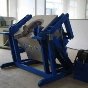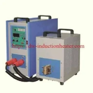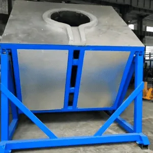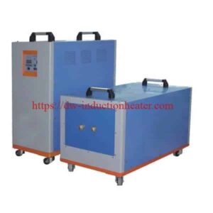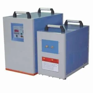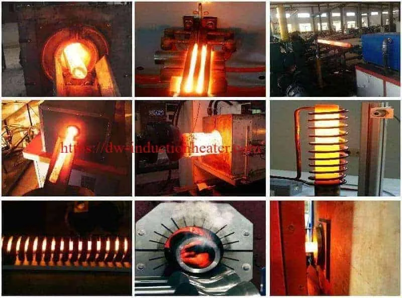
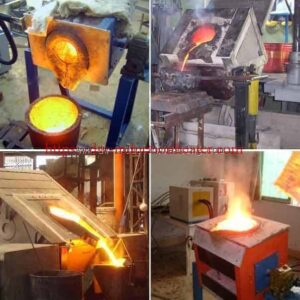
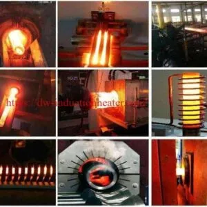
Medium Frequency Induction Generator 160KW
160kW Medium Frequency Induction Generator for Forging, Melting and Metal Heating
Quick Answer: what is medium frequency induction generator?
The HLQ DW-MF-160KW medium frequency induction generator is an industrial IGBT induction heating power supply with a published maximum oscillation power of 160kW and an operating frequency range of 1–20kHz. It converts three-phase electrical power into medium-frequency alternating current for electromagnetic heating of conductive metals. The generator is best suited to appropriately matched industrial applications requiring relatively deep heating penetration, including steel billet forging, metal rod through-heating, induction melting, shrink fitting, and selected shaft heat-treatment processes. Actual heating capacity depends on workpiece material, dimensions, heating time, coil design, electrical matching, and the real power available to the complete heating system.
Product Overview
| Product Information | Specification |
|---|---|
| Manufacturer | HLQ Induction Equipment Co., Ltd. |
| Product | Medium Frequency Induction Generator |
| Model | DW-MF-160KW |
| Maximum Oscillation Power | 160kW |
| Operating Frequency | 1–20kHz |
| Electrical Supply | Three-Phase AC 380V |
| Inverter Technology | IGBT Parallel Inverter |
| Cooling | Water Cooling |
| Primary Applications | Forging, Metal Heating and Melting |
| Operating Duty | Published 100% Duty Cycle at 40°C |
The DW-MF-160KW is part of HLQ’s industrial
medium frequency induction heating power supply
product range.
What Can a 160kW Induction Generator Do?
| Industrial Process | Heating Objective | Engineering Priority |
|---|---|---|
| Steel Billet Forging | Heat Steel Before Hot Forming | Through-Heating and Temperature Uniformity |
| Rod End Heating | Heat a Selected Section of a Rod | Localized Heating and Cycle Time |
| Induction Melting | Melt Conductive Metals | Furnace Matching and Actual Melting Capacity |
| Shrink Fitting | Expand Metal Components for Assembly | Controlled Temperature Distribution |
| Shaft Heat Treatment | Heat Selected Shaft Regions | Heating Depth and Quenching Process |
| Mold Preheating | Raise Tooling Temperature | Thermal Uniformity |
Key Applications
The DW-MF-160KW can be configured for different industrial processes using application-specific induction coils, matching components, cooling equipment, and control arrangements.
1. Steel Billet Induction Heating Before Forging
Steel billet heating is one of the most suitable applications for a medium-frequency induction generator.
An induction coil generates an alternating magnetic field that produces heat within the steel workpiece.
For forging applications, the required temperature depends on the steel grade, initial temperature, billet dimensions, and hot-forming process.
Many carbon steel forging applications operate within approximately 950–1200°C, although the correct temperature range must be selected for the specific material.
The DW-MF-160KW can be evaluated for single-station billet heating, localized end heating, or selected multi-position heating arrangements.
For complete industrial heating lines, explore HLQ’s
induction billet heating systems for forging, extrusion and rolling.
2. Steel Rod and Bar Induction Heating
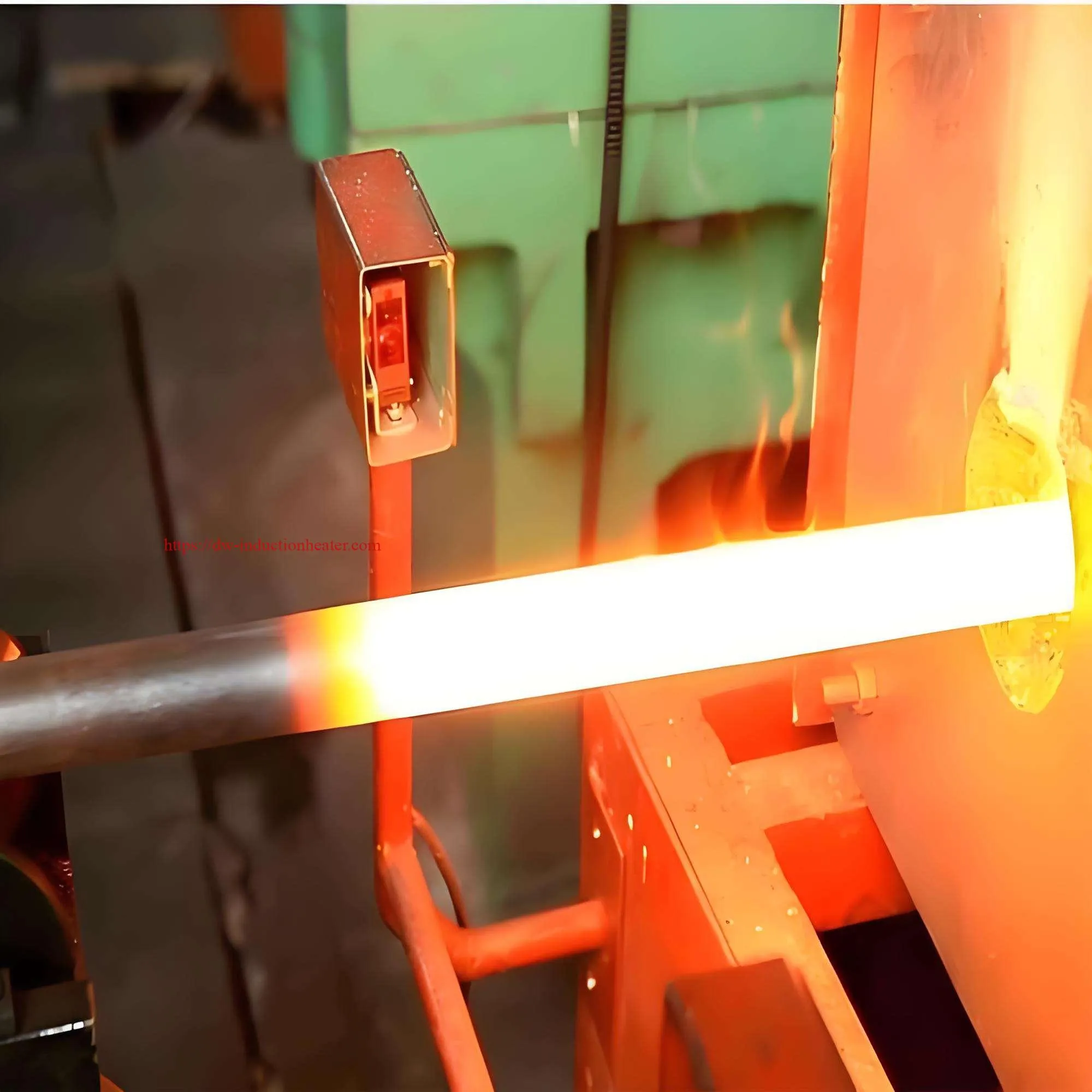
Medium-frequency induction heating is commonly used to heat steel rods and bars before hot forming.
Typical processes include rod upsetting, bar-end forging, shaft-end heating, and other metal forming operations.
A customized induction coil can be designed to heat the complete required section or a localized region of the workpiece.
The heating time must be established from the workpiece mass, required temperature rise, actual heating power, and desired temperature uniformity.
3. Induction Heating for Metal Forging
Industrial forging operations require repeatable heating conditions before the workpiece enters a forging press.
The induction heating system must provide sufficient thermal energy without excessive surface overheating.
For repetitive production, the heating station may include automatic feeding, controlled heating time, temperature monitoring, and workpiece transfer.
4. Induction Metal Melting
The DW-MF-160KW can be considered as a power supply for selected metal melting applications when combined with a compatible furnace.
Potential materials include steel, cast iron, copper, brass, bronze, aluminum, and other electrically conductive metals.
However, the generator alone does not constitute a complete induction melting furnace.
A suitable melting installation requires an induction coil, furnace body, crucible or refractory lining, electrical matching arrangement, cooling system, and molten metal handling equipment.
The maximum charge weight and melting rate cannot be determined from the 160kW maximum oscillation power alone.
5. Induction Shrink Fitting
Induction heating can temporarily expand suitable metal components before interference-fit assembly.
Applications include heating steel hubs, bearing housings, gear rings, mechanical sleeves, and selected shaft-mounted components.
The heating temperature should be determined from the material’s thermal expansion coefficient, assembly interference, dimensional tolerances, and allowable thermal stress.
6. Shaft and Gear Heat Treatment
Medium-frequency induction heating can be used for selected shaft and gear heat-treatment processes.
For induction hardening, the workpiece must be manufactured from a suitable hardenable material and heated to the required austenitizing temperature.
An appropriate quenching process is then required to achieve the intended hardness and microstructure.
The final hardened depth depends on frequency, material composition, heating time, and quenching conditions.
7. Metal Tube-End Heating
The DW-MF-160KW can be configured for localized heating of suitable metal tube ends before forming, expanding, reducing, or extrusion.
The induction coil must be selected according to the tube diameter, wall thickness, heated length, and target temperature.
8. Industrial Mold and Die Preheating
Medium-frequency induction heating can be used for selected mold and die preheating applications.
The heating arrangement must account for tooling mass, thermal conductivity, geometry, and permissible temperature gradients.
Industrial Applications Comparison
| Application | Material | Heating Requirement | Key Selection Factor |
|---|---|---|---|
| Steel Billet Forging | Carbon Steel | 950–1200°C, Grade-Dependent | Billet Diameter and Throughput |
| Alloy Steel Forging | Alloy Steel | Material-Specific Forging Temperature | Metallurgical Requirements |
| Steel Rod End Heating | Carbon / Alloy Steel | Localized Hot Forming | Heated Length and Cycle Time |
| Copper Bar Heating | Copper | Application-Dependent | Electrical Conductivity |
| Aluminum Billet Heating | Aluminum Alloy | Alloy-Specific Hot-Working Temperature | Temperature Uniformity |
| Induction Melting | Steel / Copper / Aluminum | Melting and Superheating | Furnace Configuration |
| Shrink Fitting | Steel Components | Controlled Thermal Expansion | Dimensional Tolerance |
| Shaft Heat Treatment | Hardenable Steel | Controlled Austenitizing | Required Hardened Depth |
Suitable Materials
Electromagnetic induction heating can be applied to electrically conductive materials.
However, different metals have different electrical resistivity, magnetic permeability, thermal conductivity, and heat capacity.
These properties influence induction heating performance and must be considered when selecting the operating frequency and coil arrangement.
Material Compatibility Table
| Material | Heating Characteristics | Typical Application | Engineering Consideration |
|---|---|---|---|
| Carbon Steel | Ferromagnetic Below Curie Temperature | Forging and Heat Treatment | Magnetic Properties Change During Heating |
| Alloy Steel | Grade-Dependent Magnetic and Thermal Properties | Forging and Hardening | Metallurgical Temperature Limits |
| Stainless Steel | Depends on Stainless Steel Grade | Heating and Heat Treatment | Magnetic and Nonmagnetic Grades Behave Differently |
| Copper | High Electrical and Thermal Conductivity | Billet Heating and Melting | Coil Coupling and Heating Efficiency |
| Brass | Nonferrous Copper Alloy | Forging and Melting | Alloy Composition and Temperature |
| Bronze | Properties Depend on Alloy | Heating and Melting | Alloy-Specific Process Requirements |
| Aluminum | High Thermal Conductivity | Billet Heating and Melting | Coil Design and Temperature Distribution |
| Cast Iron | Grade-Dependent | Melting and Heating | Furnace and Temperature Requirements |
Material Selection Considerations
| Material Property | Effect on Induction Heating |
|---|---|
| Electrical Resistivity | Influences Induced Current Distribution and Heating |
| Magnetic Permeability | Strongly Influences Penetration in Ferromagnetic Materials |
| Thermal Conductivity | Influences Temperature Equalization |
| Specific Heat Capacity | Determines Sensible Heating Energy |
| Workpiece Diameter | Influences Frequency and Heating-Time Selection |
| Phase Transformation | May Change Thermal and Magnetic Properties |
| Target Temperature | Determines Required Thermal Energy |
Working Principle
A medium-frequency induction generator converts industrial electrical power into controlled alternating current for electromagnetic induction heating.
The DW-MF-160KW uses solid-state IGBT inverter technology and a parallel inverter circuit.
How the DW-MF-160KW Works
- Three-phase industrial AC electricity enters the power supply.
- The rectifier and DC-link circuitry process the incoming electrical power.
- The IGBT inverter generates medium-frequency alternating electrical energy.
- The matching circuit transfers power to the induction heating coil.
- The coil generates an alternating magnetic field.
- Electrical currents are induced within the conductive workpiece.
- Electrical resistance converts the induced current into heat.
- Power and heating time are controlled according to the process requirements.
Figure 1. Medium Frequency Induction Generator Working Principle
THREE-PHASE AC POWER
          |
          v
+----------------------+
| RECTIFIER / DC LINK  |
+----------------------+
          |
          v
+----------------------+
| IGBT INVERTER        |
| DW-MF-160KW          |
+----------------------+
          |
          v
+----------------------+
| MATCHING CIRCUIT     |
+----------------------+
          |
          v
+----------------------+
| INDUCTION COIL       |
+----------------------+
          |
          v
+----------------------+
| METAL WORKPIECE      |
+----------------------+
          |
          v
ELECTROMAGNETIC HEATING

SUPPORTING SYSTEMS:
- WATER COOLING
- POWER CONTROL
- TEMPERATURE MONITORING
- ELECTRICAL PROTECTION
Why Medium Frequency Is Suitable for Through-Heating
The operating frequency affects how electromagnetic energy is distributed within conductive materials.
For a simplified conductor, electromagnetic skin depth can be expressed as:
Skin Depth = √[2ρ / (ωμ)]
Where:
- ρ = Electrical resistivity
- ω = Angular frequency
- μ = Magnetic permeability
Lower frequency generally increases electromagnetic penetration when other material properties remain unchanged.
However, induction heating depth and final temperature uniformity are not identical.
Heat conduction, workpiece diameter, magnetic-property changes, and heating time also influence the final temperature distribution.
Frequency Selection Reference
| Frequency Consideration | Heating Characteristic | Engineering Implication |
|---|---|---|
| Lower Frequency | Greater Electromagnetic Penetration | May Benefit Larger Metal Cross-Sections |
| Higher Frequency | More Surface-Concentrated Current | May Benefit Smaller or Localized Heating Zones |
| Workpiece Diameter | Changes Required Heating Distribution | Coil and Frequency Must Be Matched |
| Steel Above Curie Temperature | Magnetic Permeability Changes | Heating Characteristics Change During the Cycle |
| Nonferrous Materials | Different Electrical and Thermal Properties | May Require Different Coil Matching |
| Actual Operating Frequency | Determined by Resonant Circuit and Load | Cannot Be Selected Independently of the Equipment |
Technical Specifications
The following specifications distinguish published DW-MF-160KW product parameters from items that require engineering verification.
| Parameter | Specification | Notes |
|---|---|---|
| Product Name | Medium Frequency Induction Generator | Industrial Induction Heating Power Supply |
| Manufacturer | HLQ Induction Equipment Co., Ltd. | China |
| Model | DW-MF-160KW | Published Product Model |
| Maximum Oscillation Power | 160kW | Published Rating; Continuous Real Output Requires Verification |
| Operating Frequency | 1–20kHz | Depends on Coil and Load Matching |
| Input Voltage | Three-Phase AC 380V ±10% | Published Specification |
| Input Frequency | 50/60Hz | Published Specification |
| Published Output Current | 60–300A | Current Measurement Point and Rating Definition Must Be Confirmed |
| Maximum Input Current | Not Specified in This Product’s Technical Table | Separate Series Catalog Lists 240A; Verify Before Electrical Design |
| Inverter Technology | IGBT | Solid-State Power Electronics |
| Inverter Circuit | Parallel Inverter | Published Equipment Description |
| Cooling Method | Water Cooling | Generator and Associated Components |
| Cooling Water Pressure | >0.3MPa | Published Minimum Requirement |
| Cooling Water Flow | >20L/min | Published Requirement; Confirm Complete-System Needs |
| Duty Cycle | 100% at 40°C | Subject to Specified Operating Conditions |
| Generator Dimensions | 560 × 270 × 470mm | Published Dimensions; Confirm Supplied Configuration |
| Transformer Dimensions | 550 × 300 × 420mm | Published Dimensions |
| Generator Net Weight | 75kg | Published Value |
| Transformer Net Weight | 85kg | Published Value |
| Connecting Cable Length | 2m | Published Value |
| Overvoltage Protection | Included in Published Features | Confirm Protection Settings |
| Overcurrent Protection | Included in Published Features | Confirm Protection Settings |
| Overtemperature Protection | Included in Published Features | Equipment Protection |
| Phase-Loss Protection | Included in Published Features | Electrical Protection |
| Water-Shortage Protection | Included in Published Features | Cooling Protection |
| Power Factor | Not Published for This Model | Request Full-Load Test Data |
| Electrical Efficiency | Not Published for This Model | Request Verified Efficiency Data |
| Temperature Control | Application-Specific | Confirm Sensor and Controller Compatibility |
| Induction Coil | Customized | Must Match Workpiece and Generator |
| Automation Interface | To Be Confirmed | Specify Required Inputs, Outputs and Communications |
Important Electrical Power Definitions
For engineering selection, it is essential to distinguish generator oscillation power from real electrical input power and useful heating power.
| Parameter | Unit | Meaning |
|---|---|---|
| Apparent Input Power | kVA | Electrical Supply Loading |
| Real Input Power | kW | Actual Electrical Power Consumed |
| Maximum Oscillation Power | kW | Manufacturer-Defined Published Rating |
| Useful Heating Power | kW | Power Transferred into the Workpiece |
| Heating Energy | kWh | Electrical Energy Used Over Time |
| Specific Energy Consumption | kWh/kg or kWh/ton | Energy Required per Unit of Production |
Electrical Supply Verification
For a balanced three-phase electrical system:
S = √3 × V × I / 1000
Where:
- S = Apparent power, kVA
- V = Line voltage, V
- I = Line current, A
A separate HLQ series catalog lists a maximum input current of 240A for the DW-MF-160 power class.
If 240A is confirmed as the input line current at 380V:
S = 1.732 × 380 × 240 / 1000
S ≈ 158kVA
This is apparent input power, not verified real output power.
Real input power depends on the power factor, while useful heating power also depends on electrical conversion and heating-system losses.
Therefore, the 160kW maximum oscillation rating and the catalog input-current figure require clarification before sizing the electrical supply or confirming continuous heating performance.
Recommended Model Selection
A suitable medium-frequency induction generator should be selected according to the required thermal load, workpiece dimensions, heating time, material properties, and production capacity.
The following table provides preliminary engineering power-class ranges. These are not guaranteed model capacities.
| Application | Material | Recommended Power | Frequency |
|---|---|---|---|
| Small Steel Rod End Heating | Carbon Steel | 30–80kW Class | Selected According to Rod Diameter and Coil |
| Medium Steel Rod Forging | Carbon / Alloy Steel | 80–160kW Class | Application-Dependent MF Range |
| Higher-Throughput Rod Heating | Carbon Steel | 160–300kW Class | Selected for Heating Depth and Load Matching |
| Small-to-Medium Billet Heating | Carbon Steel | 100–250kW Class | Application-Dependent MF Range |
| Industrial Billet Forging Line | Carbon / Alloy Steel | 250kW and Above | Furnace-Specific Selection |
| Selected Metal Melting | Copper / Aluminum / Steel | Calculated from Melting Requirements | Matched to Furnace and Charge |
| Large Component Shrink Fitting | Steel | Calculated from Component Mass and Time | Application-Dependent |
| Selected Shaft Heat Treatment | Hardenable Steel | Calculated from Heating Pattern | Selected for Required Heating Depth |
Is the DW-MF-160KW Suitable for Your Application?
| Application Requirement | Preliminary Assessment | Required Engineering Verification |
|---|---|---|
| Medium Steel Bar Heating | Potentially Suitable | Diameter, Heated Length and Time |
| Localized Steel Rod Forging | Potentially Suitable | Temperature and Production Rate |
| Selected Billet Through-Heating | Potentially Suitable | Core Temperature and Coil Matching |
| Small Industrial Melting Furnace | Requires Furnace Engineering | Crucible, Coil and Melting Cycle |
| High-Throughput Billet Production | May Require More Power | Hourly Thermal Load |
| Very Large Workpiece Heating | Requires Further Evaluation | Thermal Mass and Frequency |
| Precision Shallow Surface Hardening | May Require Another Frequency Range | Case Depth and Metallurgical Requirements |
 For induction melting applications, review HLQ’s
medium frequency induction melting furnace systems.
Process Workflow
A medium-frequency induction heating system should operate according to a defined heating procedure.
The process may be manual, semi-automatic, or automated according to production requirements.
Figure 2. Induction Forging Heating Process
WORKPIECE PREPARATION
          |
          v
MATERIAL AND DIMENSION CHECK
          |
          v
COIL AND FIXTURE INSPECTION
          |
          v
COOLING SYSTEM VERIFICATION
          |
          v
WORKPIECE LOADING
          |
          v
INDUCTION HEATING
          |
          v
TEMPERATURE MEASUREMENT
          |
          v
ACCEPT / REJECT DECISION
          |
          v
TRANSFER TO FORGING PRESS
          |
          v
PRODUCTION DATA RECORDING
Process Control Table
| Process Stage | Critical Parameter | Engineering Requirement |
|---|---|---|
| Workpiece Preparation | Material and Dimensions | Confirm Production Specifications |
| Coil Inspection | Coil Condition | Check Insulation and Cooling Connections |
| System Start-Up | Cooling and Electrical Status | Confirm Required Conditions |
| Workpiece Loading | Positioning | Repeatable Coil Coupling |
| Heating | Power and Time | Follow Validated Heating Recipe |
| Temperature Measurement | Actual Workpiece Temperature | Use Suitable Temperature Instrumentation |
| Discharge | Transfer Time | Minimize Uncontrolled Temperature Loss |
| Production Monitoring | Energy and Cycle Time | Record Operating Performance |
Recommended Workpiece Temperature Checks
| Measurement | Purpose | Engineering Consideration |
|---|---|---|
| Initial Temperature | Establish Heating Requirement | Cold and Preheated Workpieces Differ |
| Surface Temperature | Monitor External Heating | Surface Does Not Necessarily Represent Core |
| Core Temperature | Verify Through-Heating | May Require Process Validation Tests |
| Exit Temperature | Confirm Forging Readiness | Use Suitable Sensor and Emissivity Settings |
| Temperature Uniformity | Assess Heating Quality | Depends on Workpiece Geometry and Heating Cycle |
Coil and Fixture Design
The induction coil is a critical component affecting heating efficiency, electromagnetic penetration, temperature distribution, and equipment reliability.
A 160kW generator cannot be evaluated independently of its coil and load-matching arrangement.
1. Solenoid Coils for Rod and Billet Heating
Multi-turn solenoid induction coils are commonly used for heating cylindrical steel rods and billets.
The coil surrounds the workpiece and generates an alternating magnetic field.
The coil inside diameter should provide suitable workpiece clearance while maintaining effective electromagnetic coupling.
The number of turns, coil length, conductor dimensions, and electrical matching arrangement must be designed together.
2. Localized Heating Coils
Short solenoid coils or specially designed inductors can be used for rod-end heating and other localized forming applications.
The coil geometry should correspond to the required heated length and temperature distribution.
3. Melting Furnace Coils
A medium-frequency induction melting furnace requires a furnace-specific induction coil and matching circuit.
The furnace coil, crucible, refractory lining, and cooling system must be selected according to the metal charge and operating requirements.
4. Coils for Shaft Heat Treatment
Induction hardening applications may require specialized coils, scanning arrangements, temperature control, and quenching equipment.
The induction frequency must be selected according to the required heating depth and workpiece geometry.
For specialized heat-treatment equipment, explore HLQ’s
induction hardening machines for steel components.
Induction Coil Design Comparison
| Application | Typical Coil Design | Main Engineering Parameter |
|---|---|---|
| Steel Rod Through-Heating | Multi-Turn Solenoid Coil | Rod Diameter and Coil Length |
| Steel Billet Heating | Customized Encircling Coil | Billet Cross-Section and Heating Time |
| Rod End Heating | Localized Multi-Turn Coil | Heated Length |
| Shaft Heat Treatment | Customized Hardening Coil | Heating Pattern and Required Depth |
| Shrink Fitting | Encircling or Application-Specific Coil | Thermal Expansion Requirement |
| Metal Melting | Furnace Induction Coil | Furnace Capacity and Electrical Matching |
Coil Design Checklist
| Parameter | Engineering Requirement | Potential Problem |
|---|---|---|
| Coil Inside Diameter | Suitable Workpiece Clearance | Poor Coupling or Mechanical Contact |
| Coil Length | Matches Required Heating Zone | Insufficient or Excessive Heating |
| Number of Turns | Matched to Resonant Circuit | Electrical Mismatch |
| Copper Tube Size | Suitable Current and Cooling Capacity | Overheating |
| Turn Spacing | Appropriate Field Distribution | Uneven Heating |
| Coil Insulation | Suitable Electrical and Thermal Protection | Insulation Failure |
| Cooling Channels | Required Water Flow | Thermal Damage |
| Fixture Design | Stable Workpiece Positioning | Inconsistent Heating |
Figure 3. Simplified Rod Heating Coil Diagram
        WORKPIECE MOVEMENT
                ----->

    =========================
    |                       |
    |       STEEL ROD       |
    |                       |
    =========================

      (((((((((((((((((((
      INDUCTION COIL
      ))))))))))))))))))

       COOLING WATER
       IN        OUT

         COIL LEADS
              |
              v
       MATCHING CIRCUIT
              |
              v
       DW-MF-160KW

Conceptual diagram only.
Not a manufacturing drawing.
5. Cooling System Engineering
The published DW-MF-160KW cooling requirement is greater than 0.3MPa with water flow greater than 20L/min.
The actual cooling system must be evaluated for the complete installation.
Additional components such as the induction coil, matching transformer, and connecting cables may require their own cooling circuits.
Cooling Heat Removal Calculation
For water, approximate cooling heat removal can be calculated as:
Cooling Power (kW) ≈ 0.0697 × Flow (L/min) × Temperature Rise (°C)
For example, at 20L/min and a cooling-water temperature rise of 10°C:
Cooling Power ≈ 0.0697 × 20 × 10
Cooling Power ≈ 13.9kW
This calculation illustrates the heat removal associated with the assumed water flow and temperature rise.
It does not determine the complete cooling requirement without knowing the generator and coil heat losses.
Cooling Water Reference Table
| Water Flow | Temperature Rise | Approximate Heat Removal |
|---|---|---|
| 20L/min | 5°C | 7.0kW |
| 20L/min | 10°C | 13.9kW |
| 20L/min | 15°C | 20.9kW |
| 30L/min | 10°C | 20.9kW |
| 40L/min | 10°C | 27.9kW |
These values are illustrative thermal calculations, not specified cooling limits for the DW-MF-160KW.
Control System and Automation
Industrial induction heating equipment should provide suitable power control, temperature monitoring, equipment protection, and production coordination.
The DW-MF-160KW published information includes overvoltage, overcurrent, overheating, phase-loss, and water-shortage protection.
Additional functions such as PLC integration, digital temperature feedback, production data logging, and industrial communication interfaces should be confirmed for the supplied configuration.
Recommended Control Functions
| Control Function | Purpose | Status |
|---|---|---|
| Heating Power Adjustment | Control Electrical Energy Delivery | Confirm Available Control Range |
| Current Monitoring | Monitor Electrical Conditions | Confirm Measurement Location |
| Frequency Monitoring | Monitor Resonant Operation | Confirm Controller Features |
| Temperature Monitoring | Measure Workpiece Temperature | Application-Specific |
| Overcurrent Protection | Protect Power Electronics | Published Feature |
| Overvoltage Protection | Protect Electrical Circuit | Published Feature |
| Overtemperature Protection | Prevent Excessive Equipment Temperature | Published Feature |
| Cooling Protection | Detect Cooling Faults | Published Feature |
| Emergency Stop | System-Level Safety | Requires Application-Specific Design |
| PLC Integration | Coordinate Heating and Material Handling | Optional; Confirm Interface |
| Temperature Feedback | Support Closed-Loop Heating | Sensor and Controller Must Be Matched |
| Data Logging | Record Production Conditions | Optional |
| Remote Communication | Factory Automation Integration | Confirm Protocol Availability |
Recommended Production Monitoring Data
| Data | Unit | Engineering Purpose |
|---|---|---|
| Workpiece Weight | kg | Determine Thermal Load |
| Heating Time | s | Monitor Cycle Performance |
| Electrical Input Power | kW | Evaluate Power Utilization |
| Electrical Energy | kWh | Calculate Specific Consumption |
| Operating Frequency | kHz | Monitor Electrical Matching |
| Workpiece Temperature | °C | Verify Heating Requirements |
| Cooling Water Flow | L/min | Verify Cooling Conditions |
| Cooling Water Temperature | °C | Evaluate Heat Rejection |
| Alarm Events | Event Records | Maintenance and Diagnostics |
Common Problems and Solutions
Induction heating problems can result from unsuitable electrical matching, insufficient cooling, inappropriate coil design, changing workpiece properties, or incorrect process parameters.
| Common Problem | Possible Cause | Recommended Engineering Solution |
|---|---|---|
| Heating Is Too Slow | Insufficient Actual Power | Measure Real Input Power and Review Heating Efficiency |
| Surface Overheating | Excessive Heating Rate or Poor Temperature Equalization | Review Frequency, Power Profile and Heating Time |
| Insufficient Core Temperature | Short Heating Time or Unsuitable Frequency | Increase Equalization Time or Redesign Heating Process |
| Uneven Heating | Incorrect Coil Geometry or Workpiece Positioning | Review Coil and Fixture Design |
| Overcurrent Alarm | Electrical Load Mismatch or Fault | Follow Manufacturer Diagnostic Procedures |
| Unstable Heating Power | Changing Load Conditions | Review Matching Circuit and Control Parameters |
| Coil Overheating | Insufficient Cooling or Excessive Current Density | Inspect Water Flow and Coil Design |
| Cooling Water Alarm | Low Flow or Cooling System Fault | Check Cooling Circuit |
| High Energy Consumption | Excessive Heat Loss or Poor Coupling | Measure kWh per kg and Review Heating System |
| Excessive Steel Scale | High Temperature or Long Exposure | Optimize Heating Cycle and Process Atmosphere |
| Inconsistent Forging Temperature | Variable Workpiece Position or Material | Standardize Loading and Temperature Monitoring |
| Machine Trips During Start-Up | Electrical Fault or Incorrect Matching | Inspect Equipment Under Approved Diagnostic Procedures |
| Frequent Equipment Alarms | Electrical, Cooling or Process Conditions Outside Limits | Review Alarm Records and Operating Data |
Recommended Troubleshooting Sequence
- Confirm that the equipment is in a safe condition.
- Review electrical and cooling alarms.
- Verify the available electrical supply.
- Measure real electrical input power.
- Check cooling flow and temperature.
- Inspect the induction coil and workpiece fixture.
- Review the electrical matching arrangement.
- Compare measured heating results with the thermal calculation.
Electrical repairs and adjustments must be performed only by qualified personnel according to the equipment manufacturer’s procedures.
Engineering Selection Guide
The correct induction heating generator should be selected using an engineering heat balance rather than power rating alone.
The main parameters are workpiece mass, material properties, target temperature, heating time, and overall heating efficiency.
1. Heating Power Calculation
The required average electrical input power can be estimated using:
P = m × Δh / (t × η)
Where:
- P = Required average electrical input power, kW
- m = Workpiece mass, kg
- Δh = Specific enthalpy increase, kJ/kg
- t = Available heating time, seconds
- η = Overall electrical-to-workpiece heating efficiency
The enthalpy increase should reflect the actual material and temperature range.
Overall heating efficiency depends on the power supply, coil coupling, workpiece geometry, insulation, and operating conditions.
2. Example: Heating Steel from 20°C to 1100°C
For a preliminary engineering calculation, assume:
| Engineering Parameter | Assumed Value |
|---|---|
| Material | Carbon Steel |
| Initial Temperature | 20°C |
| Target Temperature | 1100°C |
| Assumed Specific Enthalpy Increase | 750kJ/kg |
| Assumed Overall Heating Efficiency | 65% |
| Heating Method | Medium Frequency Induction Heating |
These values are illustrative assumptions for preliminary power sizing.
The actual steel grade, thermal properties, and equipment efficiency must be verified before final equipment selection.
3. Required Electrical Power for a 60-Second Heating Cycle
Using the assumed enthalpy increase of 750kJ/kg and overall efficiency of 65%:
| Steel Weight | Useful Thermal Energy | Heating Time | Required Average Electrical Input |
|---|---|---|---|
| 2kg | 1500kJ | 60s | 38.5kW |
| 5kg | 3750kJ | 60s | 96.2kW |
| 10kg | 7500kJ | 60s | 192.3kW |
| 15kg | 11250kJ | 60s | 288.5kW |
Engineering Interpretation:
Under these assumptions, heating a 10kg steel workpiece from 20°C to 1100°C in 60 seconds would require approximately 192kW of average real electrical input.
Therefore, a generator with a published maximum oscillation power of 160kW should not automatically be assumed capable of meeting that cycle.
Actual feasibility requires verification of the real electrical power available, coil efficiency, heating uniformity, and complete process design.
Figure 4. Required Power vs. Steel Workpiece Weight
STEEL HEATING EXAMPLE

20°C TO 1100°C
HEATING TIME: 60 SECONDS
ASSUMED EFFICIENCY: 65%

2kg   ████                 38.5kW

5kg   ██████████           96.2kW

10kg  ███████████████████  192.3kW

15kg  █████████████████████████████ 288.5kW

Values represent calculated average
electrical input power.

Not verified DW-MF-160KW performance.
4. Heating Time Comparison at Different Electrical Input Powers
Assume a 10kg steel workpiece, an enthalpy increase of 750kJ/kg, and overall heating efficiency of 65%.
| Average Real Electrical Input | Calculated Heating Time |
|---|---|
| 80kW | 144.2s |
| 100kW | 115.4s |
| 120kW | 96.2s |
| 140kW | 82.4s |
These values are mathematical energy estimates, not measured DW-MF-160KW heating times.
Real heating time can differ because of temperature gradients, changing coupling conditions, equipment limitations, and actual steel properties.
5. Energy-Based Steel Heating Throughput
For continuous production:
Throughput (kg/h) = P × 3600 × η / Δh
Assuming 750kJ/kg specific enthalpy increase and 65% overall heating efficiency:
| Average Real Electrical Input | Calculated Steel Throughput |
|---|---|
| 80kW | 250kg/h |
| 100kW | 312kg/h |
| 120kW | 374kg/h |
| 140kW | 437kg/h |
These are hypothetical energy-based throughput values.
They do not represent guaranteed production capacity for the DW-MF-160KW.
Actual output also depends on material handling, coil capacity, thermal uniformity, operating duty, and production scheduling.
6. Example: Induction Melting Energy Estimate
For metal melting applications, a separate energy balance is required.
For preliminary copper melting calculations, assume a specific electrical energy consumption of 350–500kWh per metric ton.
This range is a planning assumption, not verified performance data for the DW-MF-160KW.
| Copper Charge | 350kWh/ton | 400kWh/ton | 500kWh/ton |
|---|---|---|---|
| 50kg | 17.5kWh | 20kWh | 25kWh |
| 100kg | 35kWh | 40kWh | 50kWh |
| 150kg | 52.5kWh | 60kWh | 75kWh |
| 200kg | 70kWh | 80kWh | 100kWh |
The actual melting rate depends on the furnace structure, metal temperature, crucible, electrical matching, and real electrical input power.
7. Complete Engineering Selection Checklist
| Parameter | Required Information | Engineering Purpose |
|---|---|---|
| Material | Steel, Copper, Aluminum or Other | Determine Thermal Properties |
| Material Grade | Exact Alloy Specification | Determine Temperature Requirements |
| Workpiece Dimensions | Diameter, Length and Thickness | Select Coil and Frequency |
| Workpiece Weight | kg | Calculate Required Energy |
| Initial Temperature | °C | Determine Temperature Rise |
| Target Temperature | °C | Calculate Thermal Load |
| Heating Time | Seconds or Minutes | Determine Power Requirement |
| Production Capacity | Pieces/h or kg/h | Calculate Average Thermal Load |
| Heating Depth | Required Heating Zone | Select Frequency and Coil Design |
| Electrical Supply | Voltage, Phase and Frequency | Determine Electrical Compatibility |
| Cooling Conditions | Flow, Pressure and Temperature | Select Cooling System |
| Automation | Manual or Automatic | Define Control Requirements |
Advantages
1. Medium-Frequency Heating Capability
The DW-MF-160KW operates within a published frequency range of 1–20kHz, allowing suitable configurations for industrial heating applications requiring relatively deep electromagnetic penetration.
2. Solid-State IGBT Inverter Technology
IGBT inverter technology provides electronic power conversion for industrial induction heating.
3. Direct Electromagnetic Heating
Heat is generated within electrically conductive workpieces, reducing the need to heat surrounding furnace structures in suitable applications.
4. Flexible Industrial Applications
The power supply can be evaluated for forging, rod heating, billet heating, induction melting, shrink fitting, and selected heat-treatment processes.
5. Customized Induction Coil Matching
Application-specific coil design allows the heating arrangement to be adapted to different workpiece geometries.
6. Industrial Continuous-Duty Design
The published specification indicates a 100% duty-cycle rating at 40°C under specified conditions.
7. Multiple Protection Functions
The equipment includes published protection functions for overvoltage, overcurrent, overheating, phase loss, and water shortage.
8. Production Automation Potential
Suitable automation equipment can coordinate heating, workpiece feeding, temperature monitoring, and transfer to downstream processes.
9. Potential for Reduced Local Combustion Emissions
Electric induction heating does not require direct fuel combustion at the workpiece.
However, indirect electricity-related emissions and process-specific fumes or oxidation must still be considered.
Advantages Summary
| Advantage | Practical Customer Benefit |
|---|---|
| Localized Heating | Energy Can Be Concentrated in the Required Heating Zone |
| Electronic Power Control | Supports Repeatable Heating Cycles |
| Medium-Frequency Operation | Useful for Selected Through-Heating Applications |
| Customized Coils | Adaptable to Different Workpieces |
| Automation Integration | Supports Industrial Production Workflows |
| Protection Functions | Supports Equipment Monitoring and Protection |
Limitations
The DW-MF-160KW is not suitable for every induction heating application.
Its limitations should be considered during engineering selection.
| Limitation | Engineering Explanation | Recommended Action |
|---|---|---|
| Power Rating Definition | 160kW Is Published as Maximum Oscillation Power | Confirm Real Continuous Power Capability |
| Frequency Compatibility | 1–20kHz May Not Match Every Application | Complete Frequency and Matching Study |
| Heating Capacity | Depends on Workpiece and Time | Perform Thermal Calculation |
| Large Workpiece Heating | May Require Additional Power or Time | Evaluate Higher-Power Equipment |
| Shallow Surface Hardening | May Require Higher Frequency | Evaluate HF or SRF Equipment |
| Cooling Requirements | Complete System May Need More Cooling | Calculate Total Heat Rejection |
| Electrical Matching | Different Coils Produce Different Loads | Verify Coil and Resonant Circuit |
| Temperature Uniformity | Depends on Frequency, Geometry and Time | Validate Surface and Core Temperatures |
| Automation | Additional Equipment May Be Required | Confirm Scope of Supply |
| Electrical Installation | Input and Output Ratings Need Clarification | Use Verified Electrical Data |
When Should a Higher-Power Induction Generator Be Selected?
A higher-power generator may be required when:
- The required heating time is too short for the available power.
- The workpiece has a large mass or cross-section.
- The production line has a high hourly throughput.
- Several workpieces must be heated simultaneously.
- Large melting charges require high average electrical input.
- Additional production capacity is required for future expansion.
Why Choose HLQ Induction Equipment?
HLQ Induction Equipment Co., Ltd. supplies industrial induction heating equipment and power conversion systems for metalworking applications.
The product range includes medium-frequency induction generators, high-frequency induction heating machines, induction forging systems, metal melting furnaces, induction hardening equipment, and customized industrial heating solutions.
For the DW-MF-160KW, the correct system configuration should be determined from the workpiece, target temperature, production rate, heating cycle, induction coil, and electrical supply.
HLQ can evaluate suitable equipment configurations for industrial customers requiring induction heating power supplies and application-specific heating equipment.
Information Required for a Technical Quotation
| Customer Requirement | Information to Provide |
|---|---|
| Application | Forging, Melting, Hardening or Other |
| Material | Metal Grade or Alloy Specification |
| Dimensions | Diameter, Length and Thickness |
| Weight | kg per Workpiece |
| Heating Temperature | Initial and Target Temperatures |
| Heating Time | Seconds or Minutes |
| Production Capacity | Pieces/h or kg/h |
| Electrical Supply | Voltage, Phase and Frequency |
| Cooling | Available Cooling Conditions |
| Automation | Manual or Automatic |
| Equipment Scope | Generator Only or Complete System |
Providing accurate technical information helps ensure that the selected induction heating generator is suitable for the intended production process.
Frequently Asked Questions
FAQ 1: What is a medium frequency induction generator?
A medium frequency induction generator is an industrial electrical power supply that converts incoming AC electricity into alternating electrical power for electromagnetic induction heating.
The alternating current energizes an induction coil, generating a magnetic field that induces electrical currents inside conductive metal workpieces.
These induced currents generate heat through electrical resistance.
The HLQ DW-MF-160KW has a published maximum oscillation power of 160kW and an operating frequency range of 1–20kHz.
FAQ 2: What are the main applications of a 160kW induction heating generator?
A 160kW-class medium-frequency induction generator can be evaluated for steel rod heating, billet forging, metal hot forming, induction melting, shrink fitting, and selected industrial heat-treatment applications.
The actual applications depend on the workpiece dimensions, required temperature, operating frequency, induction coil, and available real heating power.
Larger workpieces or higher production rates may require a more powerful system.
FAQ 3: Can a 160kW induction generator heat steel billets to 1100°C?
Yes. A properly configured 160kW-class induction heating system can potentially heat suitably sized steel billets to approximately 1100°C.
However, the billet diameter, length, weight, material grade, heating time, and coil design determine whether the required process is achievable.
For example, using an assumed enthalpy increase of 750kJ/kg and overall heating efficiency of 65%, heating a 10kg steel workpiece to the specified temperature in 60 seconds would require approximately 192kW of average real electrical input.
This demonstrates why workpiece size and heating time must be considered together with generator power.
FAQ 4: What is the difference between medium frequency and high frequency induction heating?
Medium-frequency induction heating generally provides greater electromagnetic penetration than higher-frequency induction heating under comparable material conditions.
This makes medium-frequency equipment useful for selected billet heating, rod through-heating, forging, and melting applications.
Higher-frequency equipment is commonly selected for smaller workpieces and applications requiring relatively shallow or localized heating.
The correct frequency must be determined according to material properties, workpiece dimensions, required heating depth, and electrical matching.
FAQ 5: Can the DW-MF-160KW be used for induction metal melting?
The DW-MF-160KW can potentially provide electrical power to a compatible induction melting furnace.
However, a complete melting installation requires a suitable furnace body, induction coil, crucible or refractory lining, electrical matching circuit, cooling system, and molten metal handling equipment.
The generator’s maximum oscillation power does not independently establish the furnace melting capacity.
Actual melting throughput must be calculated and verified for the complete system.
FAQ 6: What cooling system is required for a 160kW induction generator?
The HLQ DW-MF-160KW is a water-cooled induction generator.
Its published specifications require cooling-water pressure above 0.3MPa and flow greater than 20L/min.
However, the complete induction heating system may require additional cooling capacity for the coil, matching transformer, and other components.
The cooling system must be designed according to the total heat rejection and the manufacturer’s operating requirements.
Adequate cooling monitoring and protection are essential for reliable operation.
FAQ 7: Can the DW-MF-160KW operate continuously for 24 hours?
The DW-MF-160KW has a published 100% duty-cycle rating at 40°C under specified operating conditions.
This indicates that the generator is designed for continuous-duty industrial operation when the electrical supply, cooling system, coil matching, and operating parameters meet the manufacturer’s requirements.
The rating does not guarantee uninterrupted operation under all environmental or loading conditions.
Continuous production requires suitable installation, monitoring, and preventive maintenance.
FAQ 8: How do I select the right medium frequency induction heating generator?
Selecting a medium-frequency induction heating generator requires evaluating the metal material, workpiece dimensions, initial temperature, target temperature, heating time, and production capacity.
The required electrical heating power can be estimated from the workpiece mass, specific enthalpy increase, available heating time, and overall heating efficiency.
The operating frequency must be selected according to electromagnetic penetration, coil geometry, and electrical matching.
For the HLQ DW-MF-160KW, the published maximum oscillation power is 160kW and the operating frequency range is 1–20kHz.
The actual continuous output capability, heating capacity, cooling requirements, and suitable induction coil must be confirmed for the intended application.
Final Engineering Summary
The HLQ DW-MF-160KW medium frequency induction generator is an industrial IGBT induction heating power supply with a published maximum oscillation power of 160kW and an operating frequency range of 1–20kHz.
It can be considered for selected steel forging, billet heating, rod heating, metal melting, shrink fitting, and industrial heat-treatment applications.
Actual heating performance depends on the complete equipment configuration, workpiece dimensions, material properties, operating frequency, heating time, electrical matching, and cooling conditions.
For reliable industrial operation, the generator should be selected through a complete engineering assessment of electrical input, thermal requirements, coil design, temperature uniformity, and production capacity.
Manufacturer: HLQ Induction Equipment Co., Ltd.
Model: DW-MF-160KW
Maximum Oscillation Power: 160kW
Operating Frequency: 1–20kHz
Electrical Input: Three-Phase 380V
Technology: IGBT Parallel Inverter
Cooling: Water Cooling
Main Applications: Forging, Billet Heating, Metal Melting and Heat Treatment