




High frequency brazing heater
Induction Brazing Machine: UHF, HF and MF Range, Brazing Cases and Model Selection
Quick Answer. An induction brazing machine heats a metal joint with an electromagnetic field until the brazing filler alloy melts and is drawn into the clearance between the parts by capillary action. The base metal is heated first, and the filler — which has the lower melting range — is the part that flows, so the copper, brass or steel itself is never taken to a damaging temperature. HLQ publishes the machine range in three frequency bands: the UHF series from 6 kW to 60 kW, published from 50 kHz up to 2.0 MHz; the HF series from 15 kVA to 120 kVA at 30–80 kHz; and the MF series from 15 kW to 160 kW at 1–20 kHz. The published brazing work sits in the UHF band: a steel tube brazed to a copper tube in about 60 seconds at 148 kHz and 954 °C, and a carbide cone brazed to a stainless steel shaft in 85 seconds at 300 kHz and 815 °C.
Quick Answer. This page is the range page: it carries the published catalogue table for the three bands, explains which band suits which brazing job, and sets out the published brazing cases with their filler, flux, temperature, frequency and cycle time. For the machine and the process in detail see the induction brazing machine for copper, brass, carbide and HVAC brazing page; for a bench or field unit see the portable induction brazing machine; and for the tube-joint duty in HVAC and refrigeration see the HVAC induction brazing machine.
Table of Contents
- What is the Induction Brazing Machine?
- Key Applications
- Suitable Materials
- Working Principle
- Technical Specifications
- Recommended Model Selection
- Process Workflow
- Common Problems and Solutions
- Engineering Selection Guide
- Advantages and Limitations
- Why Choose HLQ?
- 6 Core FAQs
What is the Induction Brazing Machine?
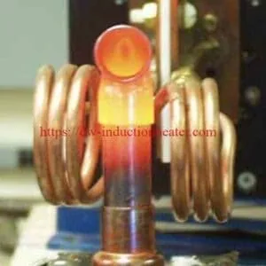
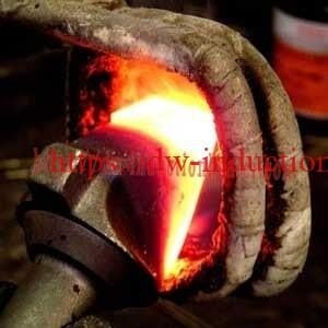
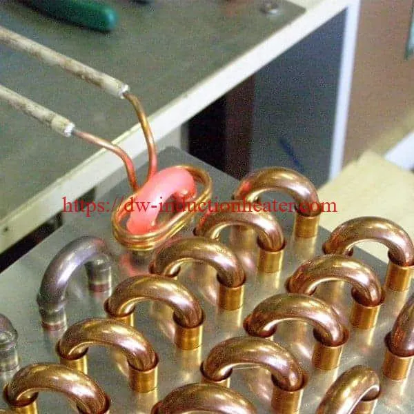
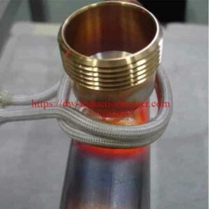
An induction brazing machine is an electromagnetic heating system that makes a brazed joint: two metal parts are cleaned, fluxed and fitted with a brazing filler alloy, an induction coil is placed around the joint, and current in the coil induces current in the parts themselves. The parts heat, the filler melts, and the molten filler flows into the joint clearance by capillary action. When the joint cools it is metallurgically continuous — not a mechanical fit and not a welded seam.
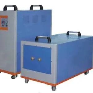
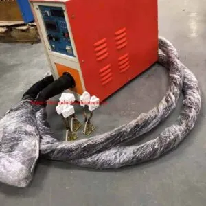
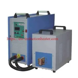
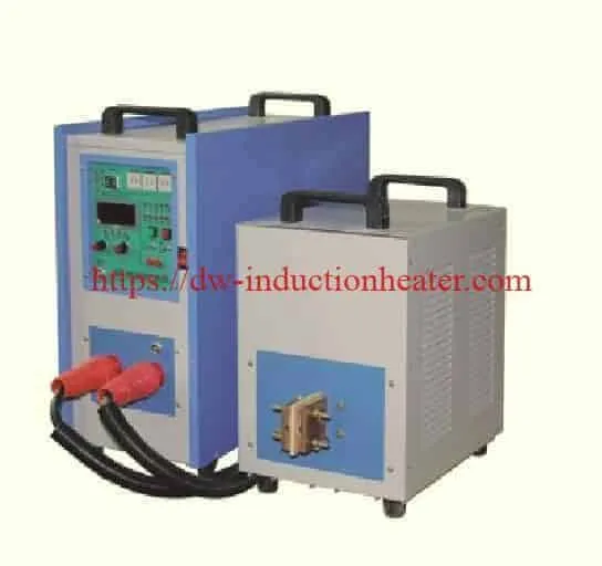
The physical machine is simpler than the process. A power supply cabinet converts mains electricity into a controlled-frequency output; a remote workhead carries the capacitor bank and the output coupling close to the work; a coil — solid, split, or flexible — is placed around or beside the joint; and the control section sets the power, the heating time and the cooling time. The published machine characteristics for this range are reproduced below exactly as the manufacturer states them, with the spelling errors cleaned up.
- First-generation IGBT module and inverting technology.
- Simple structure and light weight, and easy maintenance.
- Simple to operate — a few minutes is enough to learn it.
- Simple to install; the installation can be done very easily.
- The timer model allows the power, the operating time of the heating period and the cooling period to be preset respectively, to realise a simple heating curve. This model is suggested for batch production, to improve repeatability.
- Separated models are designed to fit the dirty surroundings of some cases.

Soldering is the same machine used with a lower-melting filler, and the range is published as a separate product: the high frequency induction soldering machine.
Key Applications
The published induction brazing applications fall into two families: joining metal parts with a filler alloy, and heating metal parts to a temperature for another purpose. The table below sets out what each published application needs.
| Published application | Materials | Published recommended power | Published frequency |
|---|---|---|---|
| Small copper tube brazing | Copper to copper, copper to brass | 5–15 kW | 80–300 kHz |
| HVAC distributor brazing | Copper tubes and brass fittings | 15–35 kW | 50–200 kHz |
| Medium copper pipe joint | Copper, brass | 25–60 kW | 30–150 kHz |
| Stainless steel tube brazing | Stainless steel, copper, nickel alloy | 15–50 kW | 50–200 kHz |
| Carbide tool brazing | Carbide to steel | 15–80 kW | 20–100 kHz |
| Diamond segment brazing | Diamond segment to steel body | 25–100 kW | 20–100 kHz |
| Electrical connector brazing | Copper, brass, silver alloy | 10–40 kW | 80–300 kHz |
| Cookware bottom brazing | Stainless steel, aluminium, copper plate | 80–250 kW | 10–50 kHz |
| Motor component brazing | Copper bars, terminals | 30–120 kW | 20–100 kHz |
| Automatic multi-station brazing | Various metal assemblies | 50–300 kW | 10–200 kHz |
Two of those applications have their own pages and their own published data. The HVAC and refrigeration duty — copper tubes to brass fittings, distributors and compressor connections — is covered on the HVAC induction brazing machine page, where the published process figures are 6–15 kW for small copper-tube joints, about 5–20 seconds per joint and a process temperature of about 700–800 °C set by the filler alloy and the base materials. The cookware duty — compound bottoms on stainless steel pans and aluminium pots — is covered on the cookware bottom induction brazing machine page.

Suitable Materials
The base material decides the filler, the temperature window and how hard the job is. The published assessment is reproduced below.
| Base material | Brazing suitability | Common filler metals | Engineering note |
|---|---|---|---|
| Copper | Excellent | Silver alloy, copper-phosphorus alloy | High thermal conductivity requires enough power and good coil coupling |
| Brass | Excellent | Silver alloy, brass brazing alloy | Control temperature to avoid zinc evaporation and discoloration |
| Carbon steel | Excellent | Silver alloy, copper alloy, nickel alloy | Magnetic material heats efficiently at lower frequency |
| Stainless steel | Good | Silver alloy, nickel alloy | Often benefits from flux or a protective atmosphere |
| Carbide | Good | Silver-copper alloy | Requires controlled heating to reduce thermal stress and cracking |
| Diamond tool segments | Good | Silver-based brazing alloy | Temperature control is critical to protect diamond performance |
| Aluminium | Possible but more difficult | Aluminium brazing alloy | Narrow temperature window and oxide film control are important |
| Copper to steel | Good | Silver alloy, copper alloy | Different heating rates require coil and fixture balancing |
| Copper to brass | Excellent | Silver alloy, copper-phosphorus alloy | Common in HVAC and plumbing components |
The published case notes show the same picture in practice. A steel tube joined to a copper tube uses a CDA 681 brazing alloy with B-1 flux, and the published parameter set is a DW-UHF-10kW at about 148 kHz, 1750 °F (954 °C), with the joint completed in about 60 seconds and a three-turn dual-diameter coil — the full worked case is on the brazing steel tube to copper tube page. A carbide cone brazed to a stainless steel shaft uses braze shims and black flux at 1500 °F (815 °C), 300 kHz and 85 seconds, and that case is published on the induction brazing shaft and carbide page.

Working Principle
The published process runs in six stages, and the control point of each stage is what makes the joint repeat rather than merely get hot. The table reproduces them.
| Stage | Physical action | Engineering control point |
|---|---|---|
| 1. Power conversion | AC input is converted into high-frequency output | Power, frequency, duty cycle and inverter stability |
| 2. Magnetic field generation | Current flows through the induction coil | Coil turns, coil diameter, copper tube size and cooling |
| 3. Workpiece heating | Eddy currents generate heat in the joint area | Coupling distance, heating depth and part position |
| 4. Filler melting | Brazing alloy melts before the base metal | Temperature window and heating uniformity |
| 5. Capillary flow | Molten filler flows into the joint gap | Joint clearance, surface cleanliness and flux |
| 6. Cooling and solidification | The joint becomes mechanically strong | Cooling speed, fixture holding time and oxidation control |
Two features of stage 4 decide the whole result. The filler alloy has a lower melting range than the base metals, so a correctly controlled joint reaches the point where the filler flows before the copper, brass or steel is damaged. And because the heating is localised to the coil, the rest of the part stays cool — which is why a brazed copper tube joint can be handled straight after the cycle, and why the published benefit list calls out less part distortion and less joint stress than welding.

Technical Specifications
The published catalogue table for the range is reproduced below, split by series for readability and otherwise unchanged. Every row and every value is as published.
M.F. series — generators, furnaces and hardening equipment
| Model | Input power max | Input current max | Oscillation frequency | Input voltage | Duty cycle |
|---|---|---|---|---|---|
| DW-MF-15 Induction Generator | 15 kW | 23 A | 1–20 kHz | 3 phases, 380 V ±10 % | 100 % |
| DW-MF-25 Induction Generator | 25 kW | 36 A | 1–20 kHz | 3 phases, 380 V ±10 % | 100 % |
| DW-MF-35 Induction Generator | 35 kW | 51 A | 1–20 kHz | 3 phases, 380 V ±10 % | 100 % |
| DW-MF-45 Induction Generator | 45 kW | 68 A | 1–20 kHz | 3 phases, 380 V ±10 % | 100 % |
| DW-MF-70 Induction Generator | 70 kW | 105 A | 1–20 kHz | 3 phases, 380 V ±10 % | 100 % |
| DW-MF-90 Induction Generator | 90 kW | 135 A | 1–20 kHz | 3 phases, 380 V ±10 % | 100 % |
| DW-MF-110 Induction Generator | 110 kW | 170 A | 1–20 kHz | 3 phases, 380 V ±10 % | 100 % |
| DW-MF-160 Induction Generator | 160 kW | 240 A | 1–20 kHz | 3 phases, 380 V ±10 % | 100 % |
| DW-MF-45 Induction Heating Rod Forging Furnace | 45 kW | 68 A | 1–20 kHz | 3 phases, 380 V ±10 % | 100 % |
| DW-MF-70 Induction Heating Rod Forging Furnace | 70 kW | 105 A | 1–20 kHz | 3 phases, 380 V ±10 % | 100 % |
| DW-MF-90 Induction Heating Rod Forging Furnace | 90 kW | 135 A | 1–20 kHz | 3 phases, 380 V ±10 % | 100 % |
| DW-MF-110 Induction Heating Rod Forging Furnace | 110 kW | 170 A | 1–20 kHz | 3 phases, 380 V ±10 % | 100 % |
| DW-MF-160 Induction Heating Rod Forging Furnace | 160 kW | 240 A | 1–20 kHz | 3 phases, 380 V ±10 % | 100 % |
| DW-MF-15 Induction Melting Furnace | 15 kW | 23 A | 1–20 kHz | 3 phases, 380 V ±10 % | 100 % |
| DW-MF-25 Induction Melting Furnace | 25 kW | 36 A | 1–20 kHz | 3 phases, 380 V ±10 % | 100 % |
| DW-MF-35 Induction Melting Furnace | 35 kW | 51 A | 1–20 kHz | 3 phases, 380 V ±10 % | 100 % |
| DW-MF-45 Induction Melting Furnace | 45 kW | 68 A | 1–20 kHz | 3 phases, 380 V ±10 % | 100 % |
| DW-MF-70 Induction Melting Furnace | 70 kW | 105 A | 1–20 kHz | 3 phases, 380 V ±10 % | 100 % |
| DW-MF-90 Induction Melting Furnace | 90 kW | 135 A | 1–20 kHz | 3 phases, 380 V ±10 % | 100 % |
| DW-MF-110 Induction Melting Furnace | 110 kW | 170 A | 1–20 kHz | 3 phases, 380 V ±10 % | 100 % |
| DW-MF-160 Induction Melting Furnace | 160 kW | 240 A | 1–20 kHz | 3 phases, 380 V ±10 % | 100 % |
| DW-MF-110 Induction Hardening Equipment | 110 kW | 170 A | 1–20 kHz | 3 phases, 380 V ±10 % | 100 % |
| DW-MF-160 Induction Hardening Equipment | 160 kW | 240 A | 1–20 kHz | 3 phases, 380 V ±10 % | 100 % |
Published note on the MF series: the input voltage is stated as “according to the application”, with 3 phases 380 V ±10 % as the standard configuration.
H.F. series — the high frequency band
| Model | Input power max | Input current max | Oscillation frequency | Input voltage | Duty cycle |
|---|---|---|---|---|---|
| DW-HF-15KW-A / DW-HF-15KW-B | 15 kVA | 32 A | 30–80 kHz | Single phase, 220 V | 80 % |
| DW-HF-25KW-A / DW-HF-25KW-B | 25 kVA | 23 A | 30–80 kHz | 3 × 380 V, 380 V ±10 % | 100 % |
| DW-HF-35KW-B | 35 kVA | 51 A | 30–80 kHz | 3 × 380 V, 380 V ±10 % | 100 % |
| DW-HF-45KW-B | 45 kVA | 68 A | 30–80 kHz | 3 × 380 V, 380 V ±10 % | 100 % |
| DW-HF-60KW-B | 60 kVA | 105 A | 30–80 kHz | 3 × 380 V, 380 V ±10 % | 100 % |
| DW-HF-80KW-B | 80 kVA | 130 A | 30–80 kHz | 3 × 380 V, 380 V ±10 % | 100 % |
| DW-HF-90KW-B | 90 kVA | 160 A | 30–80 kHz | 3 × 380 V, 380 V ±10 % | 100 % |
| DW-HF-120KW-B | 120 kVA | 200 A | 30–80 kHz | 3 × 380 V, 380 V ±10 % | 100 % |
Two published details to note in the HF table: the series is rated in **kVA** while every other series is rated in kW, and the DW-HF-25 row is published at **23 A**, below the 32 A of the smaller DW-HF-15. Both figures are reproduced as published. For the physical detail of the HF band, the published DW-HF specification adds: oscillating current 10–70 A on the 35 kW and 15–90 A on the 45 kW, duty 80 % at 30 °C on the 15 kW and 25 kW and 100 % at 30 °C on the 35 kW and 45 kW, water cooling at a maximum of 0.3 MPa and at least 6 L/min, main unit sizes of 495 × 240 × 485 mm, 550 × 240 × 485 mm and 550 × 240 × 535 mm, extension units of 340 × 205 × 340 mm and 470 × 265 × 440 mm, weights of 45, 55, 70 and 75 kg, and manual or timer control.
U.H.F. series — the ultra-high frequency band
| Model | Input power max | Input current max | Oscillation frequency | Input voltage | Duty cycle |
|---|---|---|---|---|---|
| DW-UHF-6.0KW-I | 6.0 kW | 28 A | 1.1–2.0 MHz | Single phase, 220 V ±10 % | 100 % |
| DW-UHF-6KW-II | 6.6 kW | 30 A | 200–700 kHz | 3 × 380 V, 380 V ±10 % | 100 % |
| DW-UHF-6KW-III | 6.6 kW | 30 A | 500–1100 kHz | 3 × 380 V, 380 V ±10 % | 100 % |
| DW-UHF-10KW | 10 kW | 15 A | 100–500 kHz | 3 × 380 V, 380 V ±10 % | 100 % |
| DW-UHF-20KW | 20 kW | 30 A | 50–250 kHz | 3 × 380 V, 380 V ±10 % | 100 % |
| DW-UHF-30KW | 30 kW | 45 A | 50–200 kHz | 3 × 380 V, 380 V ±10 % | 100 % |
| DW-UHF-40KW | 40 kW | 60 A | 50–200 kHz | 3 × 380 V, 380 V ±10 % | 100 % |
| DW-UHF-60KW | 60 kW | 90 A | 50–150 kHz | 3 × 380 V, 380 V ±10 % | 100 % |
Recommended Model Selection
Selection for a brazing job is made in two steps: the band first, then the model inside the band. The published band guidance is reproduced below.
| Frequency range | Heating characteristic | Typical brazing use |
|---|---|---|
| 100–500 kHz | Shallow, fast, localised heating | Small terminals, fine tubes, precision parts |
| 50–100 kHz | General high-frequency brazing | HVAC tubes, brass fittings, stainless joints |
| 20–50 kHz | Deeper heating for medium parts | Carbide tools, larger copper joints, motor parts |
| 10–20 kHz | Deeper heating for large mass parts | Cookware bottom, large tools, heavy assemblies |
The rule behind the table is physical: the higher the frequency, the shallower the current penetrates and the more localised the heating, so a small precise joint is worked at a high frequency and a heavy part is worked at a low one. The published case work confirms it — every documented brazing case in the notes sits between 148 kHz and 300 kHz, which is the UHF band.
The second step is the machine inside the band. The published workload guidance is reproduced below.
| Workpiece size / heat load | Suggested power level | Typical machine type |
|---|---|---|
| Very small joint, low mass | 3–10 kW | Portable or benchtop induction brazing machine |
| Small copper and brass parts | 10–25 kW | High-frequency induction brazing machine |
| Medium industrial joints | 25–60 kW | High-frequency or super-audio induction brazing system |
| Large carbide tools or thick tubes | 60–120 kW | Medium/high-frequency induction brazing system |
| Large plate, cookware or automated line | 120–300 kW | Customized automatic induction brazing system |
For the HF band specifically, the published HVAC mapping is reproduced below — it is the most direct published model-to-job mapping on the site.
| HVAC application | Material | Published recommended power | Suggested model |
|---|---|---|---|
| Small copper tube, below 10 mm OD | Copper to copper | 5–10 kW | DW-HF-15kW |
| HVAC copper tube joints, 10–25 mm | Copper to copper or copper to brass | 10–25 kW | DW-HF-15kW or DW-HF-25kW |
| Refrigeration compressor tube brazing | Copper, brass, steel | 15–30 kW | DW-HF-25kW or DW-HF-35kW |
| HVAC distributor brazing | Copper tubes and brass fittings | 15–35 kW | DW-HF-25kW or DW-HF-35kW |
| Brass valve and fitting brazing | Brass to copper or brass to steel | 20–40 kW | DW-HF-35kW or DW-HF-45kW |
| Larger distributors or multiple joints | Copper, brass | 40–60 kW | DW-HF-45kW or DW-HF-60kW |
The larger high-frequency machines in the range are catalogued separately: the DW-HF-160KW induction heating machine. For a job that has to be carried out at the joint rather than on a bench, the portable induction brazing machine is the published alternative.
Process Workflow
The published brazing process runs from a cleaned, fluxed assembly to a held and inspected joint. The cycle below is assembled from the published stage table and from the published case procedure, where the assembly is pre-assembled and fluxed, the filler is set as a preformed ring at the interface, the joint is then cross-sectioned after cooling to validate the result.
| Step | Operator action | Control point |
|---|---|---|
| 1 | Clean the joint surfaces and check the clearance | Surface cleanliness, joint clearance |
| 2 | Apply the flux and place the filler alloy | Correct flux and filler for the joint |
| 3 | Assemble the parts and position the coil | Coil centred on the joint, even turn spacing |
| 4 | Heat to the filler melting temperature | Temperature window and heating uniformity |
| 5 | Hold until the filler has flowed and wetted | Heating uniformity across the joint |
| 6 | Cool and hold the fixture | Cooling speed and oxidation control |
| 7 | Inspect the joint and leak test it | Wetting, clearance, contamination |
| 8 | Record the settings and release the batch | Repeatability of power and time |
Two practical points come straight out of the published case work. First, the joint is not released on time alone: the published procedure cools the assembly — in the documented case in water — and then cross-sections it to confirm that the brazing produced a sound joint. Second, where the part has a cavity that is not part of the joint, the published practice is to leave it unfluxed, because flux trapped in a countersunk hole outgasses and the pressure will push the part off its mating face.
Common Problems and Solutions
The published troubleshooting guidance is reproduced below, with the induction brazing rows first and the HVAC rows after them.
| Problem | Possible cause | Engineering solution |
|---|---|---|
| Filler metal does not flow | Temperature too low, poor surface cleaning or wrong filler alloy | Increase heating time, improve cleaning, verify the filler melting range |
| Joint overheats or burns | Excessive power, poor temperature control or the coil too close | Reduce power, use a pyrometer, adjust the coil distance |
| Uneven brazing around the tube | Coil not centred or the joint gap not uniform | Redesign the coil, improve the fixture and the alignment |
| Excessive oxidation | No flux, insufficient flux or poor gas protection | Use a suitable flux, or nitrogen or argon protection |
| Cracks in a carbide tool | Heating too fast or cooling too fast | Use a controlled ramp and slower cooling |
| Weak joint strength | Insufficient wetting, wrong joint clearance or contamination | Optimise the clearance, clean the surfaces, confirm filler compatibility |
| Power supply trips | Coil short circuit, water flow issue or a load mismatch | Check the coil insulation, the cooling flow and the matching |
| Low production efficiency | Manual loading too slow, or the heating cycle not optimised | Add a fixture, a rotary table or automatic loading |
| Inconsistent colour after brazing | Temperature variation or oxidation | Use closed-loop control and a protective atmosphere |
| Coil overheats | Insufficient water flow or the copper tube too small | Increase the cooling capacity and redesign the coil cross-section |
| Filler balls up at the mouth | Oxidation, poor flux, contamination or uneven heating | Improve cleaning, apply the correct flux, adjust the coil position |
| One part lags behind the other | Different mass and thermal behaviour, often the heavier brass fitting | Bias the coil toward the heavier part, change the coil distance or redesign the coil |
| Brass discoloration | Overheating causing zinc evaporation | Lower the power or the time and control the temperature |
| Leak at leak test | Incomplete fill from poor wetting, contamination or movement during cooling | Optimise clearance and cleaning, hold the fixture until solid, verify filler compatibility |
| Machine alarms frequently | Water shortage, overcurrent, overload or poor load matching | Check the input power, the cooling system and the coil matching |
Engineering Selection Guide
Eight questions decide whether a machine and a coil will hold up in production. Each one has a published answer.
| Question | Published reference |
|---|---|
| What is the joint, and how big is it? | Very small joint 3–10 kW; small copper and brass parts 10–25 kW; medium industrial joints 25–60 kW; large carbide tools or thick tubes 60–120 kW; large plate or an automated line 120–300 kW |
| How deep does the heat have to go? | High frequency for shallow, localised heating; medium frequency for deeper heating in large mass parts |
| What filler and flux does the joint need? | Published per base material: silver alloy, copper-phosphorus, brass brazing alloy, nickel alloy, silver-copper, EZ Flo 3 paste, black brazing flux, B-1 flux |
| What temperature window is needed? | Published brazing temperatures in the case notes run from 700 °C to 954 °C; the HVAC process range is about 700–800 °C, set by the filler and the base materials |
| What coil type fits the part? | Split clamp coils, solid coils and flexible coils; the published case work uses a three-turn dual-diameter coil and a three-turn helical coil |
| How much control is needed? | Manual, timer, or closed-loop control; the timer model with preset power, heating time and cooling time is published for batch production and repeatability |
| What is the production volume? | Manual, handheld, semi-automatic or robotic operation, chosen by production volume |
| What services does the site have? | Published HF units are water cooled at a maximum of 0.3 MPa and at least 6 L/min; the supply is single-phase 220 V or 3-phase 380 V depending on the model |
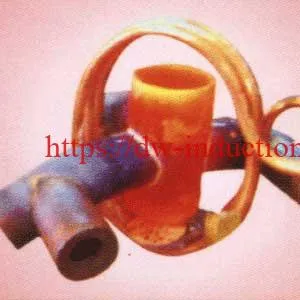
The cell that results from those answers is shown below. It is a concept rather than a certified drawing: coil design, coupling distance, fixture design, fume extraction and the cooling water circuit are all set by the parts, the filler alloy and the production layout.
Advantages and Limitations
Advantages
| Item | Induction brazing | Flame brazing |
|---|---|---|
| Heating control | High | Depends heavily on operator skill |
| Heating speed | Fast | Medium |
| Repeatability | Excellent with timer or PLC | Variable |
| Automation | Easy | Difficult |
| Oxidation | Lower with a proper process | Higher because of the open flame |
| Safety | No open flame | Open flame and gas handling required |
| Energy focus | Localized | Wider heat affected area |
| Best use | Repeatable industrial brazing | Flexible repair and low-cost manual work |
Limitations
| Limitation | Reason | Recommended action |
|---|---|---|
| Initial investment is higher than a flame torch | Power supply, coil, cooling and fixture are all required | Evaluate the total cost, the labour saving and the quality improvement |
| The coil must match the part geometry | The magnetic field distribution determines the heating result | Use custom coil design and sample testing |
| Not suitable for non-conductive materials | Induction requires a conductive or magnetic material | Use a metal susceptor or a different heating method |
| Cooling water is required | The coil and the power electronics generate heat | Use a closed-loop chiller for stable production |
| Process setup needs engineering knowledge | Power, frequency and the coil all affect the final result | Work with an experienced induction equipment supplier |
Why Choose HLQ?
HLQ Induction Heating Equipment is an induction heating manufacturer with 25 years of R&D and production experience in high-frequency, medium-frequency and ultra-high-frequency induction equipment. For a brazing buyer the relevant points are these.
- One supplier across the three bands. The same manufacturer builds the 1–20 kHz medium-frequency generators, the 30–80 kHz high-frequency machines and the 50 kHz to 2.0 MHz ultra-high-frequency machines, so a production line that mixes a heavy tool and a small tube can run on one support structure.
- The range is published in full. Every model, power, current, frequency, supply and duty cycle is on the tables above, which is what makes a band-and-model comparison possible before a quotation.
- Repeatability is designed in. The published timer model presets the power, the heating time and the cooling period separately, and is the published recommendation for batch production.
- The whole cell is documented. The workhead, the coils, the fixtures, the temperature feedback and the recording are part of the published process, not add-ons that have to be sourced separately.
- The machine fits the environment. The published separated models are designed for the dirty surroundings of some cases, and the cabinet sizes are published so a cell can be planned before delivery.
- The brazing work is documented, not claimed. The case notes published for this range give the filler, the flux, the temperature, the frequency and the cycle time for each joint, so a buyer can compare them against their own parts.
Related HLQ products published on the same equipment pages: the High frequency induction soldering machine, the Brazing Steel Tube to Copper Tube with Induction Heater, the DW-HF-160KW Induction Heating Machine, the Induction Brazing Shaft and the cookware bottom induction brazing machine. Manufacturer information is published at dw-inductionheater.com.
6 Core FAQs
1. What is the difference between brazing and soldering on this machine?
It is the filler, not the machine. In brazing the filler alloy has a lower melting range than the base metals — the published case work runs from 700 °C to 954 °C — and the joint is metallurgically continuous once it has cooled. Soldering uses a lower-melting filler on the same principle and the same hardware; the published product for that duty is the high frequency induction soldering machine, with the same MF, HF and UHF power range behind it.
2. Which frequency band do I need for my brazing job?
Match the band to how deep the heat has to go and how big the part is. The published guidance is: 100–500 kHz for shallow, fast, localised heating of small terminals, fine tubes and precision parts; 50–100 kHz for general high-frequency brazing of HVAC tubes, brass fittings and stainless joints; 20–50 kHz for deeper heating of medium parts such as carbide tools, larger copper joints and motor parts; and 10–20 kHz for deeper heating of large mass parts such as cookware bottoms, large tools and heavy assemblies. Every documented brazing case in the published notes sits between 148 kHz and 300 kHz.
3. Which model do I choose for a specific job?
Inside the band, the published workload guidance is: 3–10 kW portable or benchtop for a very small joint; 10–25 kW high frequency for small copper and brass parts; 25–60 kW high frequency or super-audio for medium industrial joints; 60–120 kW medium or high frequency for large carbide tools or thick tubes; and 120–300 kW customised automatic systems for large plate, cookware or an automated line. For the high-frequency band specifically, the published mapping runs from DW-HF-15kW for copper tubes below 10 mm OD up to DW-HF-45kW or DW-HF-60kW for larger distributors and multiple joints.
4. What actually happens at the joint?
Current in the coil induces current in the two parts, the parts heat, and the filler — which melts at a lower temperature than the base metals — melts first. The molten filler is then drawn into the joint clearance by capillary action, wets both surfaces, and on cooling forms a continuous joint. Everything the operator controls follows from that sequence: the clearance, the cleanliness, the flux, the temperature window and the hold time are the published control points of the six stages.
5. How long does a joint take, and how repeatable is it?
The published cycle times are short and they scale with the mass of the parts: the HVAC process is published at about 5–20 seconds per joint, the steel-to-copper case at about 60 seconds at 954 °C, the carbide-to-shaft case at 85 seconds at 815 °C, the carbide cap case at 11 seconds at 3.3 kW, and the carbide-teeth case at 4–5 minutes. Repeatability comes from the control: the published timer model presets the power, the heating time and the cooling period separately, and is the published recommendation for batch production.
6. What are the common failure modes, and what causes them?
Most of them are setup problems, not machine problems. The filler does not flow when the temperature is too low, the surfaces are dirty or the wrong filler is used; the joint overheats when the power is excessive or the coil is too close; the brazing is uneven around the tube when the coil is not centred or the gap is not uniform; the parts discolour when brass is overheated and zinc evaporates; and the coil overheats when the cooling water is insufficient. The documented fixes are, respectively, more heat and better cleaning, less power and a pyrometer, a redesigned coil and fixture, less power or time, and more cooling capacity.