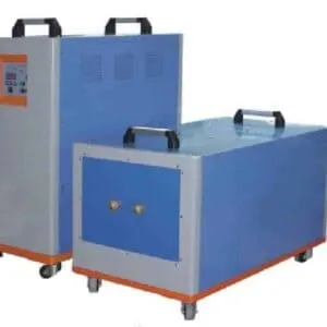
DW-HF-90kw Induction Heating Equipment
DW-HF-90kW Induction Heating Equipment – 90 kVA High Frequency IGBT Heater
Quick Answer: The HLQ DW-HF-90kW induction heating equipment is a split-type high frequency industrial heater built for localized metal heating across brazing, surface hardening, annealing, shrink fitting, soldering, preheating and mechanical assembly work. Published specifications are 90 kVA maximum oscillating power at a 30–80 kHz oscillation frequency, 99 kVA maximum input apparent power from a 3 × 380 V, 50–60 Hz supply, 30–160 A oscillating current, 0.3 MPa cooling water at ≥ 6 L/min, and a 100 % duty cycle at 30 °C. The machine weighs 110 kg, splits into a host computer of 650 × 350 × 455 mm and an extension unit of 700 × 350 × 450 mm, and connects them with a 2 m cable. Control is available in constant current or constant power mode, and heating power, current and oscillating frequency are displayed in real time.

Table of Contents
- What is the DW-HF-90kW Induction Heating Equipment?
- Key Applications
- Suitable Materials
- Working Principle
- Technical Specifications
- Recommended Model Selection
- Process Workflow
- Common Problems and Solutions
- Engineering Selection Guide
- Advantages and Limitations
- Why Choose HLQ?
- 6 Core FAQs
What is the DW-HF-90kW Induction Heating Equipment?
The DW-HF-90kW is a high frequency induction heating system: an industrial electromagnetic heater that converts three-phase industrial power into high frequency alternating current and sends that energy to a customized copper induction coil. Because the heat is generated inside the workpiece rather than applied to its surface from outside, heating is fast, non-contact and clean, and the surrounding area is not exposed to a flame.
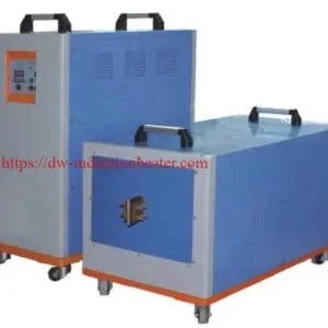
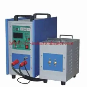
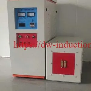
This machine is built as a split-type system with a separated main power unit and extension unit, so the power cabinet can be installed away from the immediate heating area while the heating head sits at the workstation. That is what makes the DW-HF-90KW practical for a production cell rather than only a bench.
Five published main characteristics define how it behaves in service: 100 % duty cycle with continuous working allowed at maximum power output; a light weight of 50–160 kg across the range; constant current or constant power status selectable according to the load to achieve higher heating efficiency; real-time display of heating power, heating current and oscillating frequency; and an auto-compensation circuit of frequency modulation and frequency, with a digital high-precision power start function that improves heating and brazing stability.
The DW-HF-90KW is the middle of a nine-model published DW-HF series running from 15 kVA to 160 kVA. If your duty needs a larger machine, the DW-HF-120KW magnetic induction heating equipment is the next step up; if it needs a smaller one, the DW-HF-60KW induction heater covers medium-size parts. For the complete published generator specification, see the HLQ induction heating device series.
Key Applications
The published HLQ application reference nominates the DW-HF-90 and DW-HF-120 as candidates for gear and shaft surface hardening, the DW-HF-35, 45 and 60 for medium industrial brazing, and the DW-HF-120 or a project-specific system for steel tube annealing. The 90 kVA class therefore sits at the entry point for hardening work and at the upper end of general industrial brazing.
| Application | Material | Heating Objective | Primary Requirement |
|---|---|---|---|
| Gear surface hardening | Suitable carbon and alloy steels | Localized austenitizing before quenching | Specified hardness pattern and case depth |
| Shaft surface hardening | Carbon and alloy steels | Heat a defined shaft surface zone | Correct coil, motion and quench configuration |
| Copper tube brazing | Copper and compatible alloys | Heat the joining region | Filler wetting and capillary flow |
| Carbide tool brazing | Carbide and steel | Heat the brazing interface | Thermal stress and filler compatibility |
| Steel tube annealing | Steel and selected alloys | Apply a specified thermal cycle | Temperature distribution and cooling conditions |
| Shrink fitting | Steel rings, sleeves and hubs | Produce thermal expansion | Expansion allowance and temperature limits |
| Pipe preheating | Carbon or alloy steel | Raise the selected pipe region to process temperature | Heated width and temperature control |
| Forging preheating | Steel, copper and other metals | Prepare selected metal sections for forming | Frequency selection and core temperature |
Two further HLQ pages cover the same equipment family in depth. The DW-HF-45kW high frequency induction heater covers the bench-scale end of the range with its coil design and cooling water sections, and the magnetic induction heating system page covers the complete system arrangement including automation and fixtures.
Suitable Materials
Every material behaves differently under a high frequency field, and the published heating characteristics determine which jobs the DW-HF-90KW is the right tool for. Carbon steel responds well but its magnetic properties change as the temperature rises, so the heating pattern shifts through the Curie transition during a hardening cycle.
| Material | Heating Characteristics | Typical Application | Engineering Consideration |
|---|---|---|---|
| Carbon steel | Magnetic properties change as temperature increases | Hardening, preheating, thermal assembly | Consider the Curie transition and required temperature distribution |
| Alloy steel | Electromagnetic and metallurgical properties depend on alloy composition | Gear and shaft heat treatment | Use grade-specific process requirements |
| Stainless steel | Magnetic behavior varies by grade | Annealing, brazing, localized heating | Confirm the actual stainless steel grade |
| Copper | High electrical and thermal conductivity | Brazing and electrical components | Optimize coil coupling and heating cycle |
| Brass | Conductive copper-zinc alloy | Fittings and industrial joints | Control temperature and zinc-related process risks |
| Aluminum alloys | Nonferrous and highly conductive | Selected localized heating applications | Verify power transfer and alloy-specific temperature limits |
| Nickel alloys | Properties vary significantly by composition | Specialized joining and heat treatment | Evaluate actual alloy properties |
| Carbide-steel assemblies | Dissimilar thermal properties | Cutting-tool brazing | Control filler-metal compatibility and thermal stresses |
| Property | Effect on Heating | Selection Requirement |
|---|---|---|
| Electrical resistivity | Influences electrical losses generated by induced currents | Use values appropriate to the operating temperature |
| Magnetic permeability | Influences electromagnetic current distribution | Consider magnetic transitions in ferrous materials |
| Thermal conductivity | Influences internal temperature equalization | Evaluate surface and core temperatures |
| Specific heat capacity | Influences the energy required for heating | Use a suitable temperature-dependent approximation |
| Phase transformations | May change heat demand and material properties | Consider the metallurgical process |
| Workpiece geometry | Changes coupling and effective heated mass | Use actual dimensions and heating-zone drawings |
Working Principle
Three-phase AC enters the machine and is rectified and filtered to DC. The control circuit then converts that DC into high-frequency magnetic energy, and the high-frequency current through the induction coil produces a changing magnetic field around the heating zone. The induced eddy currents generate heat inside the workpiece, and thermal conduction redistributes that heat within the material.
Because the DW-HF-90KW operates at 30–80 kHz, the current is concentrated near the surface of the workpiece. Heat is deposited in the skin layer and conducted inward, which is exactly what makes high frequency the right choice for surface hardening and shallow joint heating — and exactly why it is the wrong choice for large-section through-heating. For larger sections, lower-frequency medium frequency equipment is the correct route; the induction metals melting furnace range covers that duty.
Equipment Layout
The published layout separates three physical items: the host computer with the IGBT power electronics, DSP control, display and fault diagnosis; the extension unit carrying the high frequency transformer; and the water-cooled induction coil at the workpiece. The 2 m connecting cable is the only link between them, which is what allows the cabinet to stand clear of the heating area.
| Component | Function | Engineering Requirement |
|---|---|---|
| Main power supply | Converts incoming electrical energy into controlled power for induction heating | Correct electrical supply, grounding, protection and ventilation |
| IGBT inverter | Generates high-frequency alternating electrical current | Compatible output rating and operating frequency |
| Resonant matching circuit | Matches the induction coil and electrical load to the inverter | Appropriate inductance, capacitance and electrical operating conditions |
| Extension unit | Provides the separated heating-head or transformer arrangement | Approved electrical connections and cooling |
| Induction heating coil | Generates the alternating magnetic field | Application-specific geometry, electrical matching and cooling |
| Workpiece fixture | Positions and supports the workpiece | Stable alignment and suitable mechanical clearance |
| Heating controller | Controls the operating sequence and available heating parameters | Functions must be confirmed for the actual supplied controller |
| Cooling system | Removes heat from designated power components and the induction coil | Approved water flow, pressure, temperature and water quality |
| Protection system | Responds to specified electrical and cooling faults | Verified interlocks and safe shutdown functions |
Technical Specifications
| Technical Parameter | Published Specification | Engineering Note |
|---|---|---|
| Model | DW-HF-90KW | Manufacturer-published designation |
| Input power desire | 3 × 380 V, 50–60 Hz | Three-phase industrial supply |
| Oscillate power max | 90 kVA | Heating-circuit apparent rating, not 90 kW of useful heat |
| Oscillate frequency | 30–80 kHz | Loaded range depends on electrical matching |
| Input power max | 99 kVA | Not the same as 99 kW of active power |
| Cooling water max | 0.3 MPa, ≥ 6 L/min | Confirm whether total flow or per-circuit flow |
| Oscillating current | 30–160 A | Adjustable by load and coil design |
| Duty cycle | 100 % at 30 °C | Published claim requiring operating-condition verification |
| Weight | 110 kg | Host computer plus extension unit |
| Host computer size | 650 × 350 × 455 mm | Main power unit |
| Extension size | 700 × 350 × 450 mm | HF transformer unit |
| Cable length | 2 m | Approved length between power unit and transformer |
| Control mode | Constant current or constant power | Selectable according to the load for higher heating efficiency |
| Display | Heating power, heating current and oscillating frequency | Real-time readout for setup and troubleshooting |
| Frequency control | Auto-compensation of frequency modulation and frequency, digital high-precision power start | Improves heating and brazing stability |
Power Rating Interpretation
| Parameter | Meaning | Verification |
|---|---|---|
| Input apparent power | Electrical apparent power drawn from the supply | Published maximum: 99 kVA |
| Input active power | Actual electrical power consumed | Requires measured input kW |
| Oscillating power | Manufacturer-defined heating-circuit apparent rating | Published maximum: 90 kVA |
| Useful thermal power | Heat absorbed by the workpiece per unit time | Requires an application-specific heating test |
| Power factor | Relationship between input active and apparent power | Requires supply-side measurement |
The published 90 kVA oscillating-power rating must not be read as a guaranteed 90 kW of useful heat absorbed by a workpiece. Sizing the switchgear, the busbar and the cable on the published kVA figures alone will understate the real current draw.
Cooling Water Requirements
| Parameter | Published Information | Engineering Consideration |
|---|---|---|
| Cooling medium | Water | Confirm approved water quality |
| Published minimum flow | ≥ 6 L/min | Confirm whether total flow or individual circuit flow |
| Published pressure reference | 0.3 MPa | Confirm permitted operating pressure |
| Inlet water temperature | Not fully specified | Obtain approved limits |
| Cooling water quality | Not fully specified | Confirm hardness, conductivity, filtration and corrosion requirements |
| Cooling connections | Model-specific | Confirm hose and fitting dimensions |
| Cooling protection | Water-failure protection described | Verify actual protection functions |
| Total heat rejection | Application-dependent | Size the cooling unit using verified losses |
Recommended Model Selection
The DW-HF-90KW is one of nine published models. The series table below is the published HLQ specification for the whole DW-HF range, and it is the correct basis for choosing between them.
| Series | Model | Input Power Max | Input Current Max | Oscillate Frequency | Input Voltage | Duty Cycle |
|---|---|---|---|---|---|---|
| DW-HF-15 | DW-HF-15KW | 15 kVA | 32 A | 30–100 kHz | Single phase 220 V | 80 % |
| DW-HF-25 | DW-HF-25KW-A / -B | 25 kVA | 23 A | 20–80 kHz | 3-phase 380 V ±10 % | 100 % |
| DW-HF-35 | DW-HF-35KW-B | 35 kVA | 51 A | 20–80 kHz | 3-phase 380 V ±10 % | 100 % |
| DW-HF-45 | DW-HF-45KW-B | 45 kVA | 68 A | 20–80 kHz | 3-phase 380 V ±10 % | 100 % |
| DW-HF-60 | DW-HF-60KW-B | 60 kVA | 105 A | 20–80 kHz | 3-phase 380 V ±10 % | 100 % |
| DW-HF-80 | DW-HF-80KW-B | 80 kVA | 130 A | 20–80 kHz | 3-phase 380 V ±10 % | 100 % |
| DW-HF-90 | DW-HF-90KW-B | 90 kVA | 160 A | 20–80 kHz | 3-phase 380 V ±10 % | 100 % |
| DW-HF-120 | DW-HF-120KW-B | 120 kVA | 200 A | 20–80 kHz | 3-phase 380 V ±10 % | 100 % |
| DW-HF-160 | DW-HF-160KW-B | 160 kVA | 260 A | 20–80 kHz | 3-phase 380 V ±10 % | 100 % |
The DW-HF-25KW-A row carries a blank frequency cell in the published table; 20–80 kHz is the published series frequency. The series table lists the 90 kW class as DW-HF-90KW-B while the individual product page designates it DW-HF-90KW; both refer to the same 90 kVA, 30–160 A machine.
Where the 90 kW Class Sits
| Model | Oscillate Power | Input Power Max | Oscillating Current | Cooling Water | Weight |
|---|---|---|---|---|---|
| DW-HF-45KW | 45 kVA | 50 kVA | 15–90 A | 0.3 MPa, ≥ 6 L/min | 75 kg |
| DW-HF-60KW | 60 kVA | 66 kVA | 20–120 A | 0.3 MPa, ≥ 6 L/min | 90 kg |
| DW-HF-90KW | 90 kVA | 99 kVA | 30–160 A | 0.3 MPa, ≥ 6 L/min | 110 kg |
| DW-HF-120KW | 120 kVA | 130 kVA | 30–160 A | 0.3 MPa, ≥ 6 L/min | 135 kg |
| DW-HF-160KW | 160 kW | 160 kW | 100–1260 A | > 0.2 MPa, > 100 L/min | 80 + 75 kg |
DW-HF-160KW is published with a different structure: 380 V ±10 %, three-phase 50 or 60 Hz, 20–80 kHz, constant current control, a generator of 80 kg and an HF transformer of 75 kg, cooling water pressure above 0.2 MPa at below 40 °C and above 100 L/min, and heating and retain times of 0.1–99.9 seconds.
Application-Based Power Selection
| Application | Power Class to Evaluate | Frequency Consideration | Engineering Requirement |
|---|---|---|---|
| Small copper tube brazing | Lower-power HF equipment | Joint-specific | Confirm joint mass and filler metal |
| Medium industrial brazing | DW-HF-35 / DW-HF-45 / DW-HF-60 candidates | Application-dependent | Verify heating time and coil coupling |
| Gear surface hardening | DW-HF-90 / DW-HF-120 candidates | Selected for hardening pattern and case depth | Verify steel grade and quench system |
| Shaft surface hardening | DW-HF-90 / DW-HF-120 candidates | Matched to shaft geometry | Confirm surface and core temperature requirements |
| Steel tube annealing | DW-HF-120 or project-specific system | Depends on wall thickness and heating depth | Validate temperature distribution |
| Shrink fitting | Selected from calculated heat demand | Application-specific | Verify expansion and allowable temperature |
| Large steel billet through-heating | Evaluate medium-frequency equipment | Potentially lower than the DW-HF-120 operating range | Prioritize core temperature and thermal uniformity |
| Large metal melting | Dedicated induction melting furnace | Selected from metal and furnace design | Do not infer melting capacity from the HF generator rating |
Process Workflow
The published operating sequence for a high frequency induction heater is nine steps, each with a defined check. The sequence is what separates a repeatable process from an operator-by-feel process.
- Material identification. Confirm the material grade and the actual dimensions.
- Process definition. Specify the thermal result the job has to achieve before anything is switched on.
- Induction coil selection. Match the coil to the workpiece and the generator — a coil designed for a different job will not produce the published heating pattern.
- Cooling system inspection. Verify the approved water flow and temperature conditions before energizing.
- Electrical inspection. Verify supply, connections, grounding and protection.
- Workpiece positioning. Maintain the required heating geometry; small changes in position change the coupling.
- Induction heating. Apply the specified power and heating cycle.
- Temperature verification. Measure the required process temperature with an appropriate calibrated method.
- Process completion. Perform quenching, brazing, annealing or assembly as required.
Where temperature feedback is fitted, the machine can close the loop on the target temperature. Where it is not, the temperature display is process information only — display alone is not closed-loop control, and that distinction has to be settled before the machine is accepted.
Common Problems and Solutions
| Problem | Possible Cause | Recommended Solution |
|---|---|---|
| Slow heating | Poor coil coupling, insufficient useful power, or excessive heated mass | Verify loaded power, coil design and the heating cycle |
| Uneven heating | Incorrect coil geometry or workpiece positioning | Review field distribution and fixture alignment |
| Surface overheating | Excessive local power density or insufficient thermal equalization time | Review heating power, frequency and duration |
| Insufficient core temperature | Inadequate heating duration or unsuitable frequency | Validate cross-sectional temperature and consider alternative frequency selection |
| Insufficient hardened case depth | Unsuitable heating pattern, temperature or quench conditions | Review the complete hardening process |
| Hardening cracks | Excessive thermal gradients or unsuitable quench severity | Review steel grade, heating and quench conditions |
| Inconsistent hardness | Variable temperature or quench conditions | Improve process repeatability and verify material condition |
| Poor brazing filler flow | Unsuitable filler, contamination or inadequate joint temperature | Verify filler compatibility and surface preparation |
| Cooling water alarm | Insufficient flow, blockage or excessive temperature | Stop heating and inspect the cooling circuit |
| Generator trips at start-up | Load mismatch, low flow interlock, unstable supply voltage or wrong coil connection | Check cooling water, input power, coil connection and matching |
| Coil overheats | Insufficient cooling water or a blocked coil tube | Check water flow, clean the coil and verify cooling water pressure |
Engineering Selection Guide
Before the switchgear is ordered, work through these checks. They are the checks that determine whether the published 90 kVA becomes useful heat on the workpiece.
- Confirm the operating mode. Constant current or constant power is selectable, and the published 90 kVA and 99 kVA are circuit ratings in different places. Measure the actual input kW, RMS current and power factor at the installed supply rather than sizing from the datasheet.
- Set the target application. Gear and shaft surface hardening point to the DW-HF-90 and DW-HF-120; medium industrial brazing points down to the DW-HF-35, 45 and 60; steel tube annealing points to the DW-HF-120 or a project-specific system.
- Choose the frequency from the heating depth, not from habit. At 30–80 kHz the current is concentrated near the surface, which suits hardening and shallow joint heating. For large-section through-heating, prioritize core temperature and thermal uniformity, and evaluate medium-frequency equipment instead.
- Design the coil for the job. The published coil concepts are profile, encircling and scanning coils for gear hardening; encircling or scanning coils for shafts; helical or split coils for steel tube annealing; pancake or special-profile coils for carbide tool brazing; helical or U-shaped coils for copper tube brazing; encircling or custom-profile coils for shrink fitting; and split or custom heating coils for pipe preheating.
- Confirm the cooling provision. The coil, power components and capacitors all generate heat. Use a stable cooling supply with the specified 0.3 MPa and ≥ 6 L/min, plus water-failure protection, and treat it as production-critical rather than optional.
- Plan the controls. Confirm the actual control configuration on the supplied machine: power control, heating timer, current display, frequency display, temperature feedback, PLC integration, quench control and the safety interlocks.
- Define the acceptance test. Electrical supply, input power, oscillation frequency under load, heating time, workpiece temperature, temperature uniformity, coil compatibility, cooling water flow and cooling water pressure are the published verification items, and each has an acceptance basis.
| Function | Purpose | Configuration Status |
|---|---|---|
| Power control | Adjusts the heating load | Constant current or constant power published; confirm the supplied mode |
| Heating timer | Defines repeatable heating cycles | Confirm timer-equipped configuration |
| Current display | Monitors the heating load | Published on the DW-HF-90KW |
| Frequency display | Confirms the load matching condition | Published on the DW-HF-90KW |
| Temperature feedback | Controls the target temperature | Confirm external or integrated sensor |
| Workpiece positioning | Maintains repeatable electromagnetic coupling | Application-specific fixture |
| Scanning motion | Moves the coil or workpiece during heating | Requires suitable motion equipment |
| Quench control | Controls cooling after hardening | Requires application-specific quench equipment |
| PLC integration | Coordinates industrial production operations | Confirm interface and control scope |
| Safety interlocks | Prevents unsafe operating conditions | Must be validated for the complete installation |
For coil selection detail and the published cooling water requirements across the series, the DW-HF-45kW high frequency induction heater page sets out the coil design and cooling sections in full, and the DW-HF-35kW high frequency induction heating equipment covers the same ground one class down.
Advantages and Limitations
| Advantage | Engineering Benefit |
|---|---|
| Localized heating | Allows heat to be concentrated in the selected workpiece region |
| High-frequency operation | Supports selected surface-heating and localized applications |
| Adjustable heating control | Constant current or constant power allows process parameters to be adapted to suitable loads |
| Split-type construction | Provides flexibility in equipment positioning between the cabinet and the heating head |
| Custom induction coils | Supports different workpiece geometries |
| No direct burner flame | Does not require direct combustion at the heating station |
| Production integration | Can be combined with suitable automation and fixtures |
| Process repeatability | Supports consistent heating when operating conditions are controlled |
| Multiple industrial applications | Can be considered for hardening, brazing, annealing and thermal assembly |
| Light, movable construction | Published 50–160 kg across the range, with the 90 kW class at 110 kg |
| 100 % duty cycle | Continuous working allowed at maximum power output |
| Limitation | Engineering Consideration |
|---|---|
| Frequency selection | 30–80 kHz may not be ideal for large-section through-heating |
| Power rating interpretation | 90 kVA is not guaranteed 90 kW of useful heating power |
| Workpiece-specific coil | Different applications may require dedicated coils |
| Electrical supply | Requires a suitable three-phase industrial installation |
| Cooling requirements | Requires verified water circulation and thermal protection |
| Continuous operation | Published duty claims require defined operating conditions |
| Heating depth | Depends on frequency, material, time and thermal conduction |
| Hardening performance | Final hardness and case depth require metallurgical validation |
| Melting applications | No universal melting capacity is established for an HF generator |
| Short interconnecting cable | The published 2 m cable limits how far the heating head can be placed from the cabinet |
Why Choose HLQ?
HLQ Induction Equipment Co., Ltd. builds the complete DW-HF high frequency range and the matching medium frequency and super audio frequency series, so a single supplier can cover the whole frequency plan for a workshop rather than a single machine.
- Nine published HF models, one specification table. The DW-HF series runs from 15 kVA to 160 kVA with published power, current, frequency, voltage and duty for every model, so the model ladder can be checked rather than guessed.
- A split layout that fits a production cell. Host computer, extension unit, 2 m interconnecting cable, custom induction coil and the cooling circuit are specified as one configuration instead of four separate purchases.
- Control that is published, not implied. Constant current or constant power, real-time display of heating power, current and oscillating frequency, and the auto-compensation circuit of frequency modulation and frequency with digital high-precision power start.
- Coil engineering support. The published coil concepts cover profile, encircling, scanning, helical, split, U-shaped, pancake and custom-profile geometries, and coils can be designed against the workpiece shape.
- A complete system scope. Power supply, transformer, coil, cooling and fixture can be matched, which is what turns a generator into a working process. For the wider range, the HLQ induction heating device series covers MF, HF and UHF in one place.
- Documented verification and acceptance. The published test items — supply, input power, oscillation frequency under load, heating time, workpiece temperature, temperature uniformity, coil compatibility, cooling flow and cooling pressure — give a commissioning protocol that can be written into the purchase contract.
- Application support across the family. The DW-HF-160KW induction heating machine covers the large-billet end of the range, and the DW-HF-25KW covers the small-joint end.
6 Core FAQs
1. What is the DW-HF-90kW induction heating equipment?
It is a split-type high frequency IGBT induction heater for industrial localized metal heating. The published specification is 90 kVA maximum oscillating power at 30–80 kHz, 99 kVA maximum input apparent power from a 3 × 380 V, 50–60 Hz supply, 30–160 A oscillating current, 0.3 MPa cooling water at ≥ 6 L/min, 100 % duty cycle at 30 °C, and 110 kg total weight. It is built for brazing, surface hardening, annealing, shrink fitting, soldering, preheating and mechanical assembly work on conductive metal components.
2. How does it differ from the DW-HF-120KW?
By power class and by size. The DW-HF-120KW is published at 120 kVA oscillating power, 130 kVA maximum input, 30–160 A oscillating current and 135 kg, with a host computer of 650 × 350 × 560 mm and an extension of 700 × 350 × 460 mm. The published HLQ application reference nominates both the DW-HF-90 and the DW-HF-120 as candidates for gear and shaft surface hardening, and nominates the DW-HF-120 or a project-specific system for steel tube annealing, because tube annealing depends on wall thickness and heating depth.
3. Can a 90 kVA heater really deliver 90 kW of useful heat?
That has to be established by measurement, not by the datasheet. The published 90 kVA is the oscillating-power rating of the heating circuit and the 99 kVA is the maximum input apparent power — neither is a measurement of heat absorbed by the workpiece. The published power-density example for a 2 kg steel charge to 850 °C gives an average useful thermal power of 68.1 kW for a 15 second heating time and 17.0 kW for a 60 second heating time, and the electrical input at an assumed 50 % efficiency is correspondingly higher. Measure the loaded power on the actual workpiece and coil before the machine is accepted.
4. Why does the frequency matter so much?
At 30–80 kHz the induced current is concentrated near the surface of the workpiece, so heat is deposited in the skin layer and conducted inward. That is what makes the DW-HF range the right choice for surface hardening, shallow joint heating and shrink fitting. It is also why 30–80 kHz may not be ideal for large-section through-heating: prioritize core temperature and thermal uniformity there, and evaluate medium-frequency equipment instead.
5. What cooling water does it need, and what happens if it is wrong?
The published requirement is 0.3 MPa and ≥ 6 L/min, with water-failure protection described. The published cooling data does not fully specify inlet water temperature, water quality, connection dimensions or total heat rejection, so those must be confirmed. Insufficient cooling causes alarms, insulation damage, coil failure and safety hazards, and because the coil, power components and capacitors all generate heat, the cooling supply is production-critical rather than optional.
6. What is needed to order and commission the machine?
For selection: the workpiece material, dimensions, heated area, target temperature, required cycle time, heating depth, coil configuration and cooling conditions. For commissioning, the published verification list is electrical supply, input power, oscillation frequency under load, heating time, workpiece temperature, temperature uniformity, coil compatibility, cooling water flow and cooling water pressure, each with an acceptance basis. Send the drawing, a photograph or a sample of the workpiece so the coil can be designed, and state the test alloy and mass in the acceptance criterion.
Related HLQ resources: High Frequency Induction Heating category · DW-HF-60KW Induction Heater · DW-HF-45kW High Frequency Induction Heater · DW-HF-160KW Induction Heating Machine · HLQ Induction Heating Device Series · Magnetic Induction Heating System