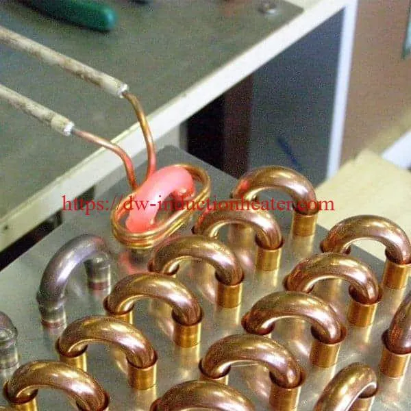




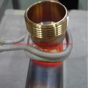


High frequency induction soldering machine
High Frequency Induction Soldering Machine for Cable, Terminal and Connector Joints
Quick Answer
A high frequency induction soldering machine heats one small joint to the liquidus of a solder alloy and stops. The solder melts and wets the base metal by capillary action, the base metal itself never melts, and the joint cools to a solid in seconds. It is a different process from brazing and a different class of machine from the brazing equipment on this site, and the difference shows up in every published number: the soldering cases run at 200 °C to 350 °C and 0.48 kW to 3.88 kW applied, where the published brazing cases run at about 618 °C to 954 °C.
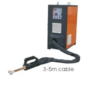
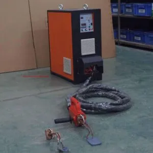
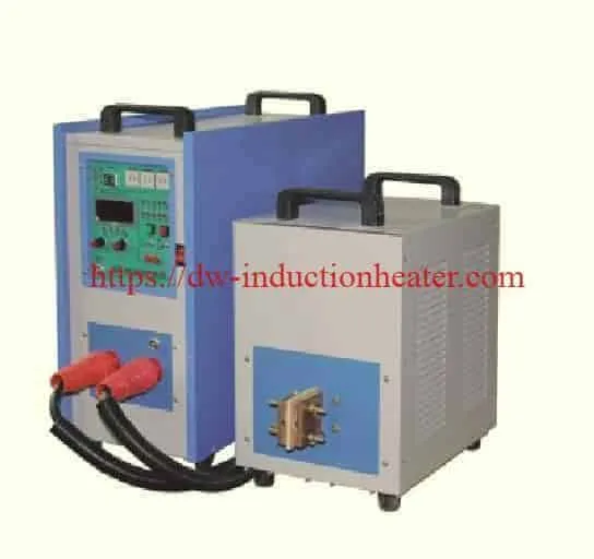
HLQ builds this equipment in the ultra high frequency band as the DW-UHF series. The published handheld unit for soldering work is the DW-UHF-6KW-III: single-phase 220 V at 50/60 Hz, 6.6 kW output, an oscillation frequency of 500–1100 kHz, input current 5–30 A, 25 kg, with a main unit of 520 × 240 × 500 mm and a heating head of 140 × 90 × 90 mm. The published six-kilowatt unit runs the third-generation IGBT inverter, holds a 100 % duty cycle at maximum output, and lets the operator select constant current or constant power mode.
The published cycle times are what make this a production method rather than a bench job. A wire soldered to a connector takes 1.5 seconds. A coaxial cable soldered to a connector ring and pin takes 5 seconds. Copper cables soldered to copper pins for an aerospace harness take 2 seconds, against the 10 minutes by hand that the published application set out to replace. The machine is small, the heat is local, and the cycle is short enough to run on an assembly line with a foot switch.
Table of Contents
- What is the High Frequency Induction Soldering Machine?
- Key Applications
- Suitable Materials
- Working Principle
- Technical Specifications
- Recommended Model Selection
- Process Workflow
- Common Problems and Solutions
- Engineering Selection Guide
- Advantages and Limitations
- Why Choose HLQ?
- 6 Core FAQs
What is the High Frequency Induction Soldering Machine?
It is a compact induction power supply with a light heating head on a flexible cable, built to bring one small joint to the solder’s liquidus. The power supply sits on the bench; the operator brings the head to the part. That is the opposite of the brazing arrangement, where a fixed coil surrounds a pipe and the machine stays where it was installed.
Four parts make up the working system:
| Part | Published specification | Role |
|---|---|---|
| Power supply and control | DW-UHF-6KW-III: 6.6 kW output, 500–1100 kHz, single-phase 220 V, 50/60 Hz, input current 5–30 A | Rectifies the supply, inverts it to the working frequency and holds the power on the program |
| Heating head | 140 × 90 × 90 mm, on a flexible water-cooled cable | Carries the coil to the joint; the published weight of the complete unit is 25 kg |
| Induction coil | Channel coil, pancake coil or a custom coil made for the joint | Creates the alternating field at the terminal and the cable end |
| Control and safety | Third-generation IGBT inverter, 100 % duty cycle at maximum output, constant current or constant power selectable | Holds the heating curve steady and protects the IGBT |
Six published product characteristics belong on the buying list for this equipment family. The first-generation IGBT module and inverting technology is used. The structure is simple and the weight is low, so maintenance is straightforward. The machine is simple to operate and a few minutes is enough to learn it, and simple to install. The timer model presets the power and the operating time of the heating period and the retain period separately, which produces a simple heating curve and is the recommended version for batch production because it improves repeatability. And the separated models are designed to fit the dirty surroundings of some cases, where the power supply has to stand apart from the work.
The published handheld line adds two further points for soldering work. With the frequency up to 500–1100 kHz, the quenching thickness can be controlled below 1 mm and very small parts can be heated easily, which is exactly what a cable or a connector joint needs. And the published applications list for that unit names brazing of tiny workpieces, diamond blade segments to carbon steel blades, PCBN blade brazing, glasses steel alloy frame brazing, small bearings quenching, annealing, jewellery brazing, watch case annealing, clock outer quenching, electronics products brazing, welding and heating, precise mechanical parts, and stainless steel strip annealing.
For the wider equipment range and the band selection behind it, see the published induction brazing machine page, which carries the full model reference across the three frequency bands, and the induction heating principle article for the heating effect itself.

Key Applications
Soldering work is small-joint work: cables into terminals, cables into connectors, wire into connectors, pins into posts, and flat copper parts to a printed board. The published applications on this site cover all of them.
| Application | Typical workpiece | What the machine has to deliver |
|---|---|---|
| Cable to terminal | 50 mm² cable into a 50 mm² terminal, harness manufacture | Heat the terminal and the stripped cable end together, without heating the whole assembly |
| Cable to connector | Coaxial cable to a connector ring and to a centre pin | Two short heats in sequence, the braid first and then the pin |
| Wire to connector | Fine wire into a connector, harnesses | A high frequency that couples into a small diameter, and very low power |
| Copper cables to copper pins | Aerospace and defence harness manufacture | A short, repeatable heat so the same joint comes out every time |
| Magnets and steel pins | Magnetic steel pins and posts for an automotive component | Control of the heat on a ferromagnetic part, with the solder fed by hand |
| Flat copper pipe to a printed board | Medical and dental equipment, heat pipes for MRI | An even heat across a flat area so the paste reflows along the whole pad |
| Brass to steel plate | Brass parts brazed to a steel plate | A silver-bearing solder with a lead-free flux, and a controlled temperature window |
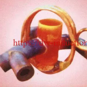
| Brass tube to a water jacket | Brass inlet and outlet tubes on a brass assembly | Heat the thin wall to soldering temperature first, then hold long enough for the alloy to even out |
The published case data is the clearest guide to what this machine is asked to do. Every figure below is HLQ’s own figure for a named joint, with the machine, the power, the temperature and the time:

| Published HLQ soldering case | Machine | Applied power | Temperature | Time |
|---|---|---|---|---|
| Wire to connector | DW-UHF-6KW-I handheld | up to 0.48 kW | 392 °F (200 °C) | 1.5 s |
| Copper cables to copper pins | DW-UHF-6KW-I handheld | 60 % power | about 600 °F (315 °C) | 2 s |
| Coaxial cable to connector ring and pin | DW-UHF-6KW-III handheld, channel coil | 3.0 kW | 662 °F (350 °C) | 5 s |
| Coaxial cable to connector ring | DW-UHF-6KW-I handheld | 1.0 kW | 662 °F (350 °C) | 5 s |
| PCB board with copper pipe | DW-UHF-6KW-III handheld, coated custom coil | 3.88 kW | low-temperature solder paste | 8 s |
| Magnetic steel pins and posts | DW-UHF-6KW-I at 214 kHz, pancake coil | pulsed | 470 °F (243 °C) | under 10 s |
| Cable to terminals | DW-UHF-6KW-I handheld | 2.8 kW | 500 °F (260 °C) | 15–20 s |
| Brass to steel plate | DW-UHF-6KW-I handheld | 2 kW | 535–585 °F (279–307 °C) | 21 s |

Three things in that table decide a purchase. The applied power is small — the published soldering cases run between 0.48 kW and 3.88 kW, because a small joint holds very little heat. The temperatures run from 200 °C to 350 °C, which is the solder’s liquidus and not the base metal’s melting point. And most of these joints were run on the DW-UHF handheld lines, so the machine selection starts with the size of the part and the frequency needed to couple into it, not with the joint alone.
For the copper-tube side of the family and the way filler and flux are chosen for refrigeration work, see the published induction brazing HVAC pipes page, and for the machine range itself the induction brazing machine for copper, brass, carbide and HVAC brazing page.

Suitable Materials
The joint is usually a copper-to-copper or brass-to-brass job, but the parts that carry the heat are small, and the solder has to wet them without the base metal reaching its own melting point. The published combinations are listed below.
| Combination | Published application | Published filler and flux | Engineering note |
|---|---|---|---|
| Copper to copper | Cable to terminal, coaxial cable to connector, copper cables to copper pins | Sn60Pb38Cu2 solder, or no-flux solder wire where the joint allows it | Low melting point metals heat fast; the frequency has to match the diameter of the part |
| Brass to brass | Brass tube to a brass water jacket assembly | Lead-free solder alloy with utility paste soldering flux | The thin wall reaches soldering temperature first; hold long enough for the alloy to even out |
| Brass to steel | Brass part soldered to a steel plate | Harris Stay-Brite #8 silver bearing solder with Harris Bridgit lead-free soldering flux | The two metals heat at different rates; the coil position decides the result |
| Copper to a printed board | Flat copper pipes on a PCB for medical equipment | Low-temperature solder paste | A coated custom coil was used so the coil would not suffer mechanical damage |
| Magnets and magnetic steel | Magnetic steel pins and posts for an automotive component | Rosin core solder | Sand the insulation off the wire first; a foot pedal lets the operator feed the solder by hand |
Two material rules matter. The solder has to reach its own liquidus and stop there, because the base metal must stay solid — that is what separates soldering from brazing, and HLQ’s own brazing reference states that brazing gives higher joint strength in most industrial applications precisely because it uses a higher-temperature filler and a stronger metallurgical bond. And the flux has to be chosen for the joint: the published coaxial cable case uses a no-flux solder wire, while the published brass-to-steel case needs a paste flux with the silver-bearing alloy.
For the filler families in the wider brazing and soldering family, the published table below applies.
| Filler family | Typical use | Flux needed? |
|---|---|---|
| Copper-phosphorus (Cu-P) | Copper-to-copper joints | No: self-fluxing on copper |
| Copper-phosphorus-silver, 15 % Ag | Standard alloy for refrigeration service and repair joints | No on copper; yes on brass |
| Copper-phosphorus-silver, 5 % Ag | Lower-cost copper joints | Cheaper, but does not perform as well as 15 % Ag |
| Silver brazing alloy (Ag-based) | Copper to brass, copper to steel, stainless steel | Yes: paste flux on both surfaces |
Phosphorus-bearing fillers must not be used on steel, because they form brittle phosphides. The published selection order is: base materials, then joint design, then operating pressure, then operating temperature, then the applicable HVAC and refrigeration standards, and finally the production requirements.

Working Principle
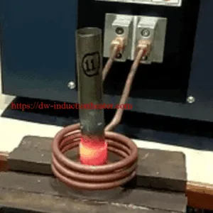
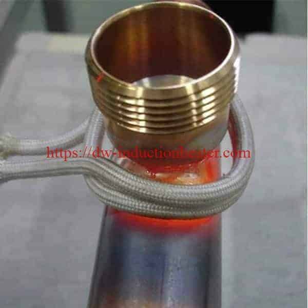
The heat is generated inside the parts, not in a soldering iron tip and not in a flame. Mains electricity is rectified and inverted by the IGBT stage into the working frequency, the matching circuit transfers that power to the coil, and the coil’s alternating magnetic field induces current in the terminal and the cable end. The resistance of the metal turns that induced current into heat, and the solder in the gap reaches its liquidus while the copper and brass stay solid.

Because the heating is electromagnetic rather than a visible flame or a heated tip, the size of the part decides the frequency. The published wire-to-connector case makes the point explicitly: the unit was run at 985 kHz because the wire was of a small diameter, and the reason for using such a high frequency was to couple into it. The published cable-to-metallic-plate case makes the same point in the other direction: the complete process can be achieved in less than 5 seconds by increasing the frequency from under 200 kHz to over 300 kHz, and by increasing the power.
| Stage | Physical action | Engineering control point |
|---|---|---|
| Power conversion | AC input is converted into high frequency output | Power, frequency, duty cycle |
| Magnetic field generation | Current flows through the induction coil | Coil turns, coil diameter, cooling water |
| Joint heating | Eddy currents heat the terminal and the cable end | Coupling distance, part position, heating time |
| Filler melting | The solder reaches its liquidus; the base metal does not melt | Temperature window, heating uniformity |
| Capillary flow | Molten solder wets the base metal and fills the gap | Joint clearance, cleanliness, flux |
| Solidification | The joint cools to a solid | Cooling time, disturbance of the part |
The published magnetic steel case shows the machine handling the work the way an operator expects it. The part was placed in the coil and the power turned on; after seven seconds the solder began to flow and the solder was fed to the joint; the power was then pulsed for one additional second to let the solder continue to feed, and the overall process took less than ten seconds. In the published coaxial cable case the same two-step pattern appears: three seconds to bring the braid and the connector to temperature, then one and a half seconds on the centre pin.

Technical Specifications
Published DW-UHF-6KW-III handheld soldering heater
| Parameter | Published specification |
|---|---|
| Model | DW-UHF-6KW-III (new product) |
| Input voltage | Single phase 220 V, 50-60 Hz |
| Output power | 6.6 kW |
| Oscillation frequency | 500-1100 kHz |
| Input current | 5-30 A |
| Weight | 25 kg |
| Size, main unit | 520 × 240 × 500 mm |
| Size, heater head | 140 × 90 × 90 mm |
| Inverter | Third-generation IGBT inverter technology |
| Duty cycle | 100 %, continuous working at maximum power output |
| Output control | Constant current or constant power selectable |
| Published applications | Quick quenching; hardening for small depth; brazing for tiny workpieces; heating tiny workpieces; diamond blade brazing to segments; carbon steel blade brazing; PCBN blade brazing; glasses steel alloys frame brazing; small bearings quenching; annealing; jewellery brazing; watch case annealing; clock outer quenching; electronics products brazing, welding and heating; precise mechanical parts brazing and heating; stainless steel strip annealing |
Published DW-UHF series range
| Model | Input power desired | Oscillation frequency | Maximum oscillation power | Duty cycle | Cooling water desired |
|---|---|---|---|---|---|
| DW-UHF-4.5KW | AC 1 × 220 V, 50 or 60 Hz | 1100-2000 kHz | 4.5 kW | 80 % | 0.2 MPa, below 30 °C, 5 L/min |
| DW-UHF-6KW-I | AC 1 × 220 V, 50 or 60 Hz | 900-2000 kHz | 6 kW | 80 % | 0.2 MPa, below 30 °C, 5 L/min |
| DW-UHF-6KW-III | AC 1 × 220 V, 50 or 60 Hz | 500-1100 kHz | 6.6 kW | 100 % | 0.2 MPa, below 30 °C, 6 L/min |
| DW-UHF-10KW | AC 3 × 380 V, 50 or 60 Hz | 100-300 kHz | 10 kW | 100 % | 0.2 MPa, below 30 °C, 6 L/min |
| DW-UHF-20KW | AC 3 × 380 V, 50 or 60 Hz | 50-250 kHz | 20 kW | 100 % | 0.2 MPa, below 30 °C, 6 L/min |
| DW-UHF-30KW | AC 3 × 380 V, 50 or 60 Hz | 50-200 kHz | 30 kW | 100 % | 0.2 MPa, below 30 °C, 6 L/min |
| DW-UHF-40KW | AC 3 × 380 V, 50 or 60 Hz | 50-200 kHz | 40 kW | 100 % | 0.2 MPa, below 30 °C, 6 L/min |
| DW-UHF-60KW | AC 3 × 380 V, 50 or 60 Hz | 50-150 kHz | 60 kW | 100 % | 0.2 MPa, below 30 °C, 6 L/min |
| DW-UHF-100KW | AC 3 × 380 V, 50 or 60 Hz | 50-150 kHz | 100 kW | 100 % | 0.2 MPa, below 30 °C, 6 L/min |
Two published points on this range need saying plainly, because they decide which machine a soldering job needs. First, the band falls as the power rises: the soldering work sits at the top of the range, where the frequency is highest and the power lowest. That is why the published soldering cases run on the 6 kW handheld lines and why the 100 kW end of the range is a different class of machine for different work. Second, the model naming on this page does not reconcile with the handheld page: the general table prints DW-UHF-6KW-I at 6.0 kW, 28 A and 1.1–2.0 MHz with a single-phase 220 V supply and a 100 % duty cycle, while the handheld page prints the same model at 900–2000 kHz, 6 kW and an 80 % duty cycle, and prints DW-UHF-6KW-III at 150–500 kHz on a three-phase 380 V supply where the handheld page prints it at 500–1100 kHz on single-phase 220 V. Confirm the band, the supply and the duty cycle of the exact machine being quoted; they decide whether the coil couples at all.
Published frequency band context
| Frequency type | Typical frequency range | Heating depth | Common application |
|---|---|---|---|
| KGPS medium frequency | 0.1–10 kHz | Deep | Melting furnace, large steel heating |
| Medium frequency | 0.2–20 kHz | Medium depth | Forging, melting, deep heating |
| Super audio frequency | 20–50 kHz | Medium depth | Medium-depth hardening, brazing |
| High frequency | 30–80 kHz | Shallow surface | Surface hardening, brazing |
| Ultra high frequency | 50 kHz–2 MHz | Very shallow | Small parts, thin surface heating |
The published application power and frequency reference completes the picture: small part brazing 5–40 kW at 30–300 kHz, and pipe preheating and PWHT 30–300 kW at 2–30 kHz. Soldering sits at the shallow, high-frequency end of that list, which is why the machine that fits a soldered connector joint is a handheld unit and not a cabinet.
Recommended Model Selection
For soldering, the model is chosen from the size of the part and the frequency needed to couple into it. The published cases show the pattern: the smallest wire work was run at 985 kHz on the DW-UHF-6KW-I, the coaxial connector work at 500–1100 kHz on the DW-UHF-6KW-III, and the magnetic steel pin work at 214 kHz on a DW-UHF-6KW-I configured with a remote workhead and a pancake coil.
| Your job | Published model candidates | Reason |
|---|---|---|
| Very fine wire into a connector, harnesses | DW-UHF-6KW-I at the top of its band | The published case ran at 985 kHz to couple into a small diameter, at up to 0.48 kW |
| Coaxial cable to a connector ring and pin | DW-UHF-6KW-III with a channel coil | Published at 500-1100 kHz, 3.0 kW and 5 s for the two-step joint |
| Copper cable to terminals, larger harness work | DW-UHF-6KW-I | Published at 2.8 kW and 15-20 s, with the time to temperature about 4-5 s |
| Magnetic steel pins and posts | DW-UHF-6KW-I with a remote workhead and a pancake coil | Published at 214 kHz with a single-position two-turn coil and a pulsed finish |
| Flat copper parts on a printed board | DW-UHF-6KW-III with a coated custom coil | Published at 3.88 kW and 8 s, with a coated coil to survive handling |
| Brass to steel, or brass to brass assemblies | DW-UHF-6KW-I, or DW-HF-15KW | Published at 2 kW for brass to steel; the published brass tube case used DW-HF-15KW at 5 kW |
| A production station rather than a bench job | DW-UHF-6KW with the timer model | The published timer model presets the heating and retain periods for repeatability in batch production |
| Work beyond small joints — pipes, tools, larger assemblies | The brazing equipment range | The brazing filler liquidus is above 450 °C and needs a different machine class; see the brazing pages |
One published comparison is worth keeping in mind when choosing between a bench unit and a cabinet. The DW-UHF-6KW-III is published at 25 kg with a 140 × 90 × 90 mm heating head, so it goes to the joint rather than the joint coming to the machine. That is what makes a 1.5 second cycle possible on an assembly line with a foot switch, and it is also why the same process can move from a handheld unit to an automated cell without changing the heating method.
For the equipment range across all three frequency bands, and for the coil and matching arrangements, see the published induction brazing machine page and the handheld induction heater 6KW page.
Process Workflow
One joint runs through eight steps. Each step has one control point that decides whether the next step can start.

- Prepare the joint. Strip the cable and clean the terminal; sand the insulation off a magnetic steel part. Clean metal and a close fit are the control point, because the solder has to wet the surface.
- Apply the flux. Flux goes on the surfaces where the alloy needs it, or a no-flux solder wire is used where the joint allows it. Flux on the right surfaces is the control point.
- Position the coil. The coil covers the terminal and the cable end, close to the joint. Coupling distance and part position are the control point.
- Set the cycle. Power and frequency are set on the machine, then the heat time and the hold. The power and the frequency are the control point, because the frequency is what couples into the part.
- Heat to liquidus. The joint reaches the liquidus of the solder alloy. The metal temperature is the control point, not the coil temperature.
- Feed the solder. The solder is fed into the joint while the heat is on. A continuous fillet all the way round is the control point.
- Stop and cool. Stop the power and leave the part alone until it solidifies. The heat is off before the cooling starts.
- Inspect the joint. Check the fillet and the joint, then record the cycle. A sound, repeatable joint is the control point.
Two published cases show how the operator works inside this cycle. In the magnetic steel pin case, a foot pedal was part of the setup to facilitate manual feeding of the solder: the part was placed in the coil, the power turned on, and after seven seconds the solder began to flow and was fed to the joint, with the power pulsed for one additional second. In the cable-to-terminal case, the assembly was positioned inside the coil, the time to temperature was about 4 to 5 seconds, the temperature was held constant to complete the soldering process, and a foot switch was used to start and stop the machine; the joint was soldered after 15 to 20 seconds.

Common Problems and Solutions
| Problem | Likely cause | Recommended solution |
|---|---|---|
| The solder does not flow | The joint has not reached the liquidus, or the surface is dirty or oxidised | Clean the parts, check the heat time against the published case figure for that joint, and confirm the temperature |
| The solder flows on one side only | Uneven coil coupling or an open-coil gap | Centre the coil, rotate the part, pulse the power |
| The base metal discolours or softens | Too much power or too long a heat, or the frequency is too low for the part | Reduce the power or the time, and raise the frequency to couple into a smaller diameter |
| The joint is cold on the far side | The coil is too large for the part, or the fixture lets the part move | Use a coil made for the joint and a fixture that holds the part in the same place |
| The joint is overheated after the solder has flowed | The heat was not stopped when the fillet closed | Stop the power at full flow; the published case stops on a continuous fillet |
| The solder does not wet the base metal | Wrong filler for the joint, missing flux, or too little heat | Choose the filler and flux for the combination, and extend the cycle |
| The coil overheats | Insufficient cooling water, a blocked cooling channel or overload | Check the water flow, pressure and quality, and the coil connections |
| Equipment alarms frequently | Water failure, phase failure, overload or poor load matching | Check the utilities, the cooling system, the coil matching and the protection settings |
| Every joint is different | The heat is being judged by eye instead of set on the machine | Use the timer model so the heating and retain periods are preset, and record the cycle |
The published comparison with torch soldering makes the commercial case concrete: heat control depends on operator skill with a torch and on set power and time with induction; the heated area is wide with a flame and localised to the joint with induction; there is open flame and fuel gas in one case and none in the other; oxidation and distortion are higher with a flame; cycle consistency is variable with a torch and consistent part to part with induction; and automation is straightforward rather than difficult.
Engineering Selection Guide
- Decide whether the job is soldering or brazing. The published brazing definition is a filler metal liquidus above 450 °C / 840 °F, and the published brazing cases reach 618–954 °C. The published soldering cases reach 200–350 °C. If the alloy in the drawing has a liquidus above 450 °C, this is brazing work and it needs the brazing equipment, not a soldering head.
- Size the part, then set the frequency. The frequency has to couple into the diameter of the part. The published wire case ran at 985 kHz for a fine wire; the published magnetic steel pin case ran at 214 kHz on a 7.9 mm post with a remote workhead; the published cable-to-plate case improved from 14 seconds to under 5 seconds by raising the frequency from under 200 kHz to over 300 kHz and increasing the power.
- Start from the published case figure for that joint. The published power, temperature and time for a named joint are the reference point, and the coil is designed around them.
- Choose the filler and the flux together. No-flux solder wire where the joint allows it, a paste flux with a silver-bearing or lead-free alloy where it does not, and never a phosphorus-bearing filler on steel.
- Check the supply and the cooling. The published handheld units run on single-phase 220 V, so a workshop outlet is enough, and the published cooling figure is 0.2 MPa at below 30 °C with 5 to 6 L/min.
- Plan the cycle control. If more than one person runs the station, the timer model is what makes the joints identical, because the heating power, the heating time, the retain power and the retain time are preset rather than judged by eye.
- Plan the station. The published case set includes a foot switch to start and stop the machine and to feed the solder by hand, and a fixture or locating guide so the part sits in the coil in the same place every time.
- Decide the acceptance check. The published quality check is to inspect the joint and, for a critical harness, to record the cycle for the quality file.
For the wider heating reference and the band selection behind the machine, see the site’s induction heating principle article, and for the copper-tube and refrigeration work see the HVAC induction brazing machines page.
Advantages and Limitations
Advantages
- Seconds, not minutes. The published cases run from 1.5 seconds to 21 seconds per joint, and the published aerospace harness case set out to replace a 10 minute hand operation with under a minute.
- Only the joint heats. The heat is generated inside the terminal and the cable end, so the rest of the assembly stays at ambient and the part does not distort.
- Repeatable. Set power and set time remove the operator from the result, which is what makes the process automatable on an assembly line.
- No flame and no fumes at the station. There is no open flame and no fuel gas, and less heat radiates around the operator.
- Light enough to carry. The published handheld unit is 25 kg with a 140 × 90 × 90 mm heating head, so the machine goes to the joint.
- Less oxidation. A short, concentrated heat in air produces less oxide than a torch or a heated tip.
- Remote operation. The published cases use a foot switch, and the process can be automated on a line because the system can be turned on remotely.
- Multiple parts at once. Where a multi-joint coil is used, several joints can be soldered in the same cycle.
Limitations
| Limitation | Engineering explanation | Recommended action |
|---|---|---|
| Small joints only | The published soldering cases are all small parts at 0.48 kW to 3.88 kW | For pipes, tools and larger assemblies use the brazing equipment instead |
| The base metal must not melt | The solder liquidus has to sit below the melting point of the part | Check the alloy and the base metal before quoting the machine |
| The frequency must match the part | A poor frequency choice gives no coupling or an overheated surface | Set the frequency for the diameter of the part, as the published cases do |
| Small parts need a custom coil | The published PCB case used a coated custom-made coil so the coil would not suffer mechanical damage | Design and coat the coil for the actual part |
| The operator still feeds the solder | Solder is fed by hand while the heat is on | Use the foot switch and the fixture, and train the operator on the feed |
| Cooling is still required | The published cooling figure is 0.2 MPa at below 30 °C with 5 to 6 L/min | Provide the cooling even on a bench unit |
| Published model data conflicts | The general table and the handheld page disagree on the band, the supply and the duty cycle of the same model | Confirm the exact machine specification before ordering |
| Oxide still forms in air | A long heat in air oxidises the joint | Shorten the cycle, use flux, or purge with nitrogen where the published case does |
One published caution is worth repeating: the values in the published cases are application examples, not guaranteed cycle times. A larger joint, a different alloy or a different fixture will change the result, and the process has to be proven on a sample before it goes into production.
Why Choose HLQ?
HLQ Induction Equipment Co., Ltd. supplies industrial induction heating equipment and power conversion systems for metalworking applications. The published product range covers ultra high frequency, high frequency and medium frequency induction generators, induction forging systems, metal melting furnaces, induction hardening equipment and customised industrial heating solutions. For a soldering station, the correct configuration is determined from the joint, the filler alloy, the diameter of the part and the production rate, not from the kilowatt figure alone.
The information a technical quotation needs is short and specific:
| Customer requirement | Information to provide |
|---|---|
| Joint | What is joined to what, the diameters and the wall thicknesses |
| Alloy | The solder or filler alloy and the flux |
| Target temperature | The liquidus of the alloy, and the melting point of the base metal |
| Cycle time | Seconds per joint, and the joints per hour required |
| Access | Whether the head can reach the joint, or the part has to come to the coil |
| Electrical supply | Single-phase 220 V for a handheld unit, or three-phase 380 V for a cabinet |
| Cooling | Available water flow and pressure, and the inlet temperature |
| Operation | Handheld with a foot switch, bench station, or automated cell |
| Documentation | Whether the cycle has to be recorded per joint |
The related published pages for this equipment family are the portable induction brazing machine page, the handheld induction heater 6KW page and the magnetic induction heating system page.
Related HLQ products
- HVAC induction brazing machines join copper tubes
- Induction Brazing Pipe-to-Pipe End Lap Joints
- HVAC Brazing with Induction Heating System
- Induction Brazing Machine for Copper, Brass, Carbide and HVAC Brazing
6 Core FAQs
1. What is a high frequency induction soldering machine?
It is an induction power supply with a light heating head that heats one small joint to the liquidus of a solder alloy. The solder melts and wets the base metal by capillary action while the copper or brass itself stays solid, and the joint cools to a solid in seconds. HLQ publishes the DW-UHF handheld line for this work, with the DW-UHF-6KW-III at 6.6 kW output, 500–1100 kHz, single-phase 220 V, 25 kg and a 140 × 90 × 90 mm heating head.
2. How is induction soldering different from induction brazing?
The temperature. The published brazing definition is a filler metal liquidus above 450 °C / 840 °F, and the published brazing cases run from about 618 °C to 954 °C. The published soldering cases run from 200 °C to 350 °C, at 0.48 kW to 3.88 kW. HLQ’s own brazing reference states that brazing gives the higher joint strength in most industrial applications because it uses the higher-temperature filler, so the process choice follows the alloy on the drawing.
3. How fast is a soldered joint?
The published cases give 1.5 seconds for a wire soldered to a connector, 2 seconds for copper cables soldered to copper pins, 5 seconds for a coaxial cable soldered to a connector ring and pin, 8 seconds for copper pipe on a printed board, under 10 seconds for magnetic steel pins, 15 to 20 seconds for a cable soldered to a terminal and 21 seconds for brass soldered to a steel plate. In the published aerospace harness case, 2 seconds replaced a 10 minute hand operation.
4. How is the frequency chosen for a small part?
From the diameter of the part, because the current has to couple into it. The published wire-to-connector case ran at 985 kHz specifically to couple into a small wire diameter; the published magnetic steel pin case ran at 214 kHz on a 7.9 mm post with a remote workhead and a two-turn pancake coil; and the published cable-to-plate case was brought from 14 seconds down to under 5 seconds by raising the frequency from under 200 kHz to over 300 kHz and increasing the power.
5. Which solder and flux does a joint need?
The published cases use several. Cable to terminals uses Sn60Pb38Cu2 solder with a foot switch. Coaxial cable to a connector uses a no-flux solder wire. Brass to steel uses a silver-bearing solder with a lead-free soldering flux, at 535 to 585 °F. Brass tube to a water jacket uses a lead-free solder alloy with a utility paste flux. And phosphorus-bearing fillers must not be used on steel, because they form brittle phosphides.
6. Does a soldering machine need cooling and a fixture?
Both. The published cooling figure for the DW-UHF handheld units is 0.2 MPa at below 30 °C with 5 to 6 L/min, even on a 25 kg bench unit. And the published cases use a fixture or locating guide so the part sits in the coil in the same place every time, because the position of the part in the field is what decides whether the heat lands on the joint.