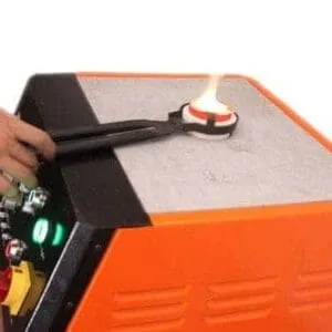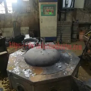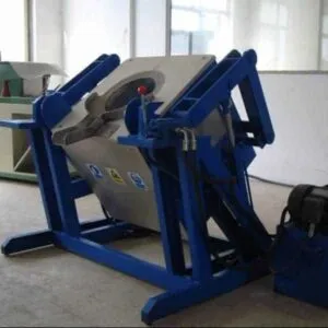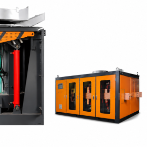



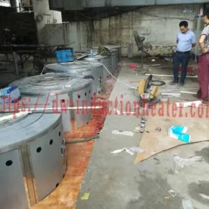
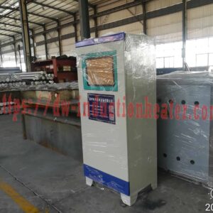
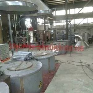
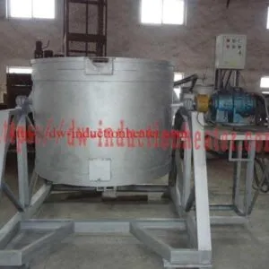

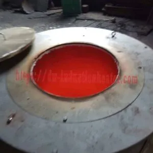
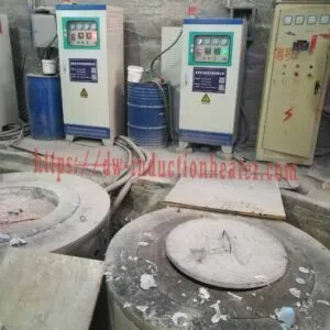
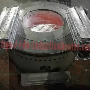
Series Connection Mid Frequency Aluminum Melting Furnace
Series Connection Mid Frequency Aluminum Melting Furnace: Melting and Keep-Warm on One Furnace, 150–1,200 kg per Heat
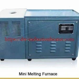
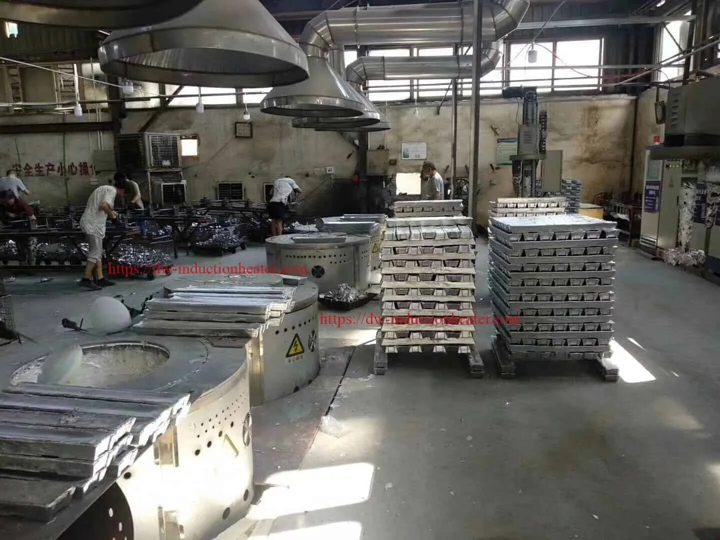
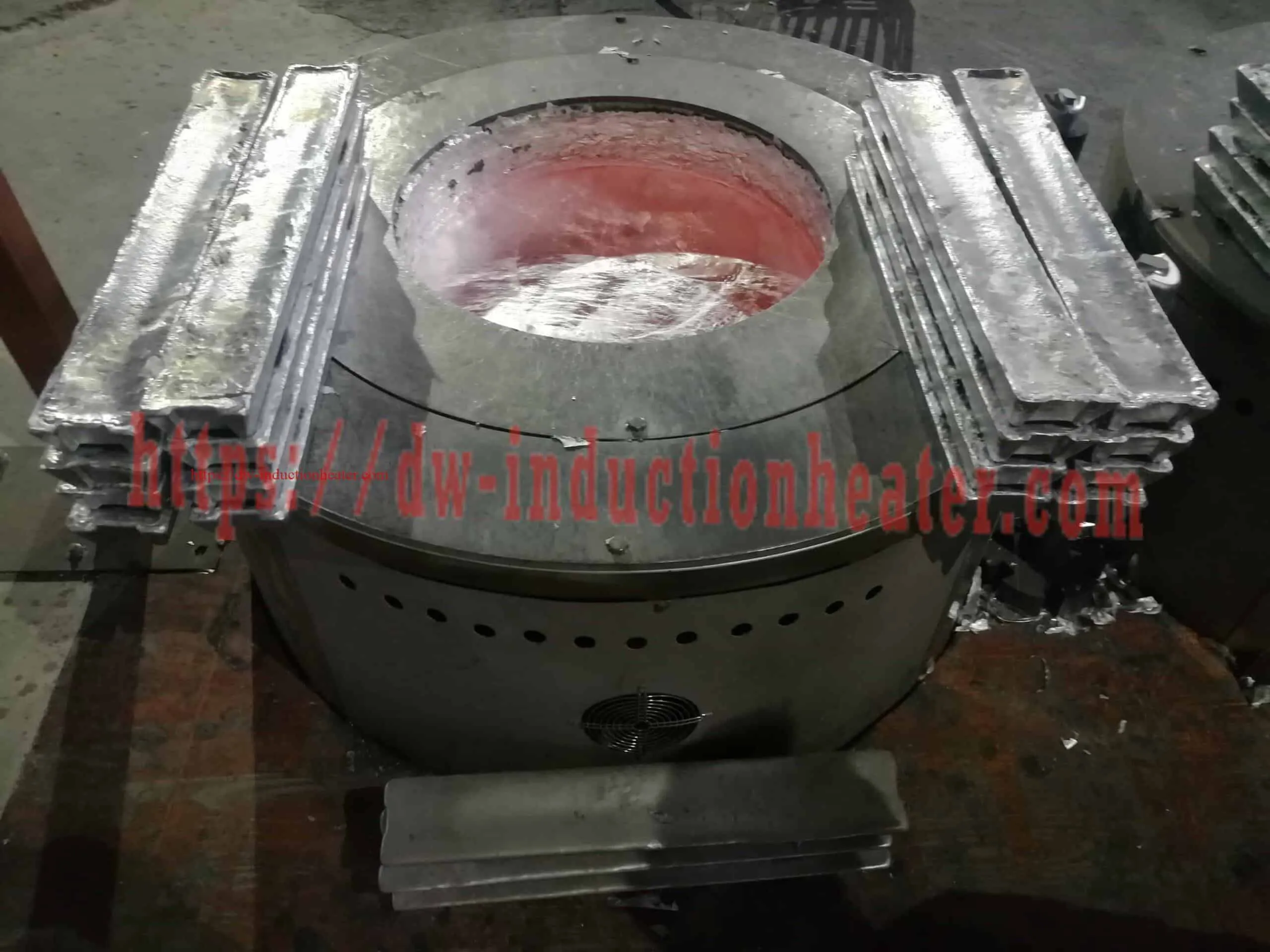
A series connection mid frequency aluminum melting furnace is a coreless crucible furnace in which the medium-frequency generator, the compensating capacitor and the induction coil form a resonant tank with the capacitor connected in series with the load. HLQ publishes the SMJD series in 13 models from 60 kW to 200 kW, with an aluminium melting capacity of 150 kg to 1,200 kg per heat, three-phase 380 V supply at 50–60 Hz, and an oscillation frequency published as 1–100 kHz with custom frequency available.
Two duties sit on this page, because both belong to the same furnace. The first is melting: a charge is brought to a liquid state at full power, with electromagnetic stirring keeping the bath even. The second is keep warm: the power is reduced and the melt is held at its pouring temperature for as long as the process needs it. That second duty is what makes this furnace family useful beyond the melt itself, and it is also where the energy budget and the furnace selection actually differ.
The materials in view are the low-melting-point non-ferrous metals — aluminium, zinc, tin and lead — because the frequency, the crucible, the atmosphere and the holding temperature are all set by the metal rather than by the name on the machine. For the broader HLQ range across every metal, see the induction melting furnace for steel, iron, copper, aluminium and gold page, and for the engineering reference across the whole range see the induction furnace page.
Quick Answer
The HLQ series connection mid frequency aluminum melting furnace is a medium-frequency induction crucible furnace built for two duties — melting and keeping warm — on low-melting-point non-ferrous metals. The published specification is:
- Aluminium capacity — 150 kg to 1,200 kg per heat, from SMJD‑480 at 150 kg up to SMJD‑3100 at 1,200 kg. (The page previously advertised “100^1200kg”; the published table shows 150 kg as the smallest entry.)
- Input power — 60 kW to 200 kW, with the electrical table publishing the same numbers as output power.
- Supply — three-phase 380 V, 50–60 Hz, with a neutral (“+N”) shown on the parameter sheet.
- Oscillation frequency — 1–100 kHz, customisable according to the customer’s request. On the medium-frequency line the working frequency is designed by changing the coil and the compensating capacitor according to the melting material, quantity, stirring effect, working noise and melting efficiency.
- Temperature — pure aluminium melts at about 660 °C and is held for pouring in the 680–760 °C range, inside a furnace rated to 1,800 °C.
- Control — LED digital temperature controller with PID heating control, accuracy described as up to 3 °C, with digital PLL frequency tracking and automatic load impedance matching.
- Duty — 100 % load duration at maximum power for 24-hour continuous operation, which is what makes the keep-warm duty practical on the same machine.
What is not published matters here. There is no holding time, no holding temperature and no throughput figure for any model, and no per-model melting time for the SMJD series. The published power-density reference for holding is 100–200 kW/t, which is the number to size the electrical installation against for a keep-warm duty. Every figure on this page is quoted from HLQ’s own parameter sheet, melting furnace manual and published technical references.
Table of Contents
- Quick Answer
- What is the Series Connection Mid Frequency Aluminum Melting Furnace?
- Key Applications
- Suitable Materials
- Working Principle
- Technical Specifications
- Recommended Model Selection
- Process Workflow
- Common Problems and Solutions
- Engineering Selection Guide
- Advantages and Limitations
- Why Choose HLQ?
- 6 Core FAQs
What is the Series Connection Mid Frequency Aluminum Melting Furnace?
A series connection mid frequency aluminum melting furnace is a batch crucible furnace in which a medium-frequency current runs through a water-cooled copper coil around a conductive crucible. The alternating magnetic field induces eddy currents in the charge, the resistance of the metal converts that energy into heat, and the heat passes into the charge until the aluminium melts. The same rotating field stirs the bath, so temperature and composition stay even before the pour.
What makes this configuration distinct is where the compensating capacitor sits. In a series-connected tank the capacitor is in series with the load — one current path runs through generator, capacitor, load and coil — rather than across the terminals. That arrangement is not the only one HLQ builds. On HLQ’s current-inverting medium-frequency generators the published description is of a parallel oscillating circuit, realised by the current-inverting technology with soft-switching resonance dual-control and frequency tracking, and that parallel circuit is what gives the medium-frequency series generator its characteristics. Both are legitimate arrangements; they are simply different circuits, and the choice is a specification decision rather than a marketing one.
Three published consequences follow from the topology, and they are the reason it is worth specifying by name. Automatic frequency tracking follows the load as the metal melts and its impedance changes. Load impedance matching is automatic as the bath changes. And the capacitor bank is sized as part of the furnace order, not added to it later as an accessory.
For the wider HLQ range across every metal, and for the engineering reference across all capacities, see the induction melting furnace and induction furnace pages. For the medium-frequency machine set in detail — generator, compensating capacitors and the three furnace body types — see the medium frequency induction melting furnace page.

Product categories: Induction Melting Furnace and Aluminum Melting Furnace.
Key Applications
Two duties, and the published duty ladder for each:
| Duty | What it means | Published power density |
|---|---|---|
| Melting | Bringing a charge to a liquid state at full rated power, with electromagnetic stirring active | Rapid batch, ingot charge: 450–600 kW/t Standard batch, mixed charge: 350–450 kW/t Scrap remelting, variable density: 300–400 kW/t |
| Keep warm (holding) | Holding the melt at its pouring temperature after melting, with power reduced to offset heat losses | Holding only: 100–200 kW/t |
| Continuous supply | Steady-state melt and hold feeding a downstream process such as a casting machine | Continuous casting, melting plus holding: 250–350 kW/t |
Published applications for the low-melting-point non-ferrous metals this furnace family serves:
| Application | Metal | Key requirement |
|---|---|---|
| Aluminium casting and die casting | Aluminium ingots, Al-Si / Al-Mg / Al-Cu alloys, clean scrap | Stable melt temperature, low dross, rapid cycle |
| Zinc alloy die casting and galvanizing | Zinc alloys | Precise melt rate and temperature; covered crucible or inert gas against oxidation |
| Tin and tin alloy production | Tin and tin alloys | Lower melting point with a different stirring need; medium frequency suits the faster melt |
| Lead and lead alloy secondary smelting | Lead, from clean scrap and returns | Low frequency for deeper penetration into the larger batches |
| Secondary remelting and recycling | Clean, dry aluminium, copper, zinc and lead scrap | High throughput, low melt loss, scrap flexibility |
| Ingot and bar production | Low-melting-point non-ferrous alloys | Consistent melt quality into refractory-lined moulds |
Two published routes sit outside this furnace and should not be confused with it. The rotary route — HLQ publishes a tilting rotary furnace for smelting and recycling aluminum, zinc, lead and non-ferrous metals — mixes the charge by rotation and taps from the bottom, which suits a continuous smelting duty differently. And where zinc has to be recovered rather than lost to fume, that is a vacuum metallurgy process: HLQ publishes the induction melting furnace for lead, tin and zinc reference, the induction zinc alloy melting furnace, and a dedicated vacuum route in the vacuum distillation furnace for copper-zinc separation and recovery.


Suitable Materials
The published operating temperatures and linings across the metals this furnace family is specified against:
| Metal | Typical melting / operating temperature | Published lining or crucible |
|---|---|---|
| Aluminium alloys | Pure Al melts at about 660 °C; usual operating range 680–760 °C | Graphite, SiC-graphite or high-alumina |
| Aluminium alloy scrap | Alloy dependent | Published in the SMJD aluminium capacity column |
| Pop cans (used beverage containers) | About 660 °C | Published in the SMJD aluminium capacity column |
| Aluminium slag and dross material | Alloy dependent | Published in the SMJD aluminium capacity column |
| Zinc alloy | Low temperature | Low-temperature-compatible refractory lining; covered crucible, flux or inert gas |
| Tin and tin alloys | Lower melting point, with different stirring needs | Covered crucible or flux to control oxidation |
| Lead and lead alloys | Low temperature, deeper penetration needed | Low-frequency operation suits the larger batches |
| Copper (Cu-ETP) | About 1083–1100 °C | Magnesia lining; graphite or SiC crucible on small furnaces |
| Brass / tin bronze | About 850–1000 °C | Silica or alumina; graphite or SiC crucible |
| Gray cast iron | About 1150–1400 °C | Acidic, neutral or basic refractory lining |
| Ductile iron | About 1300–1500 °C | Acidic, neutral or basic refractory lining |
| Carbon steel / low-alloy steel | About 1450–1650 °C | Acidic, neutral or basic refractory lining |
| Stainless steel | About 1400–1550 °C | Neutral or basic lining |
| Gold | Furnace maximum about 1200–1400 °C | Graphite or clay-graphite crucible |
The published frequency guidance per metal is aluminium ≈ 0.5–20 kHz, copper ≈ 0.25–8 kHz, iron and steel ≈ 0.5–2.5 kHz and gold ≈ 1–80 kHz, with the lower frequency used for the larger furnaces. On the lead, tin and zinc reference HLQ states the selection rule more precisely: low frequencies, tens to a few hundred hertz, provide deeper penetration for larger batches and suit lead and zinc, while medium frequencies in the kHz range are common for faster melting of smaller batches and for tin, whose lower melting point and stirring needs differ.

Working Principle
The heating route is the same for every SMJD furnace. Through the internal rectifier and filter circuit the AC supply is converted into DC power; the control circuit then converts that DC power into high-frequency magnetic energy. The high-speed changing current through the coil produces a high-speed changing magnetic field. When the magnetic field lines pass through the crucible, numerous small eddy currents are generated inside it, so the crucible itself is heated at high speed, and that heat is transferred to the metal and melted into a liquid state.
For the two duties on this page, the sequence is:
| Stage | What happens | Consequence for the keep-warm duty |
|---|---|---|
| 1. Power conversion | The rectifier and filter circuit convert the AC supply into DC, and the control circuit converts that DC into high-frequency energy | Sets the plant connection, the power factor and the harmonics the transformer must tolerate |
| 2. Inversion | An IGBT generator produces the medium-frequency output | IGBT for small and medium furnaces; SCR/KGPS for large melting capacity |
| 3. Resonant tank | The coil and the compensating capacitors form the resonant circuit that matches the supply to the furnace load | In the series connection the capacitor is in series with the load, in one current path with generator, capacitor, load and coil |
| 4. Frequency tracking | Digital PLL tracking and automatic load impedance matching follow the load as it changes | The tank stays matched as the metal melts and the bath impedance settles |
| 5. Eddy-current heating | Eddy currents are generated inside the crucible and the metal; heat is produced in the charge itself | No combustion product reaches the melt, so a hold does not add dross |
| 6. Electromagnetic stirring | The magnetic force stirs the melting pool, easing the floating of flux and the oxides | Keeps the held bath homogeneous, so temperature does not stratify over a long hold |
| 7. Melting | The charge softens, collapses and forms a molten bath; extra charge is added as the first batch melts | Full rated power, at the rapid-batch or standard-batch power density |
| 8. Keep warm | Power is reduced and the melt is held at the pouring temperature | Holding power density is published at 100–200 kW/t — the figure to size the installation against |
| 9. Pouring | The furnace is tilted — manual, electrical or hydraulic — into a ladle or moulds | Hydraulic tilting is recommended for medium and large furnaces |


Technical Specifications
SMJD series — published model table
The table below reproduces the original published numerical values. Its header is offset in the source, so the aluminium figure is the third numeric column in each published row; the first is the steel column and the second is the copper, gold and silver (scrap, slag) column. The steel column duplicates the aluminium column in all 13 rows, which is an upstream defect in the source table rather than a specification.
| Model | Published power (kW) | Published input current (A) | Published aluminium capacity (kg per heat) | Crucible designation |
|---|---|---|---|---|
| SMJD-463 | 60 | 90 | 200 | 463# |
| SMJD-480 | 60 | 90 | 150 | 480# |
| SMJD-580 | 80 | 120 | 200 | 580# |
| SMJD-600 | 60 | 90 | 230 | 600# |
| SMJD-900 | 120 | 180 | 300 | 900# |
| SMJD-905 | 80 | 120 | 300 | 905# |
| SMJD-1250 | 80 | 120 | 400 | 1250# |
| SMJD-1250 | 120 | 180 | 450 | 1250# |
| SMJD-1500 | 120 | 180 | 500 | 1500# |
| SMJD-1550 | 120 | 180 | 520 | 1550# |
| SMJD-1700 | 160 | 240 | 600 | 1700# |
| SMJD-2300 | 160 | 240 | 800 | 2300# |
| SMJD-3100 | 200 | 300 | 1,200 | 3100# |
The two SMJD-1250 entries are retained separately because their published power and aluminium capacity differ, and the source supplies no suffix to explain the difference. The published power is labelled “Input Power” in the capacity table and “Output Power” in the electrical table for the same numbers; that inconsistency has to be confirmed. Listed currents are reproduced for traceability and must not be used on their own to size the electrical installation: at three-phase 380 V the published kW divided by the apparent power at the published current is 1.013 in every row, so the two columns describe output and input respectively and only close at a power factor near 1.
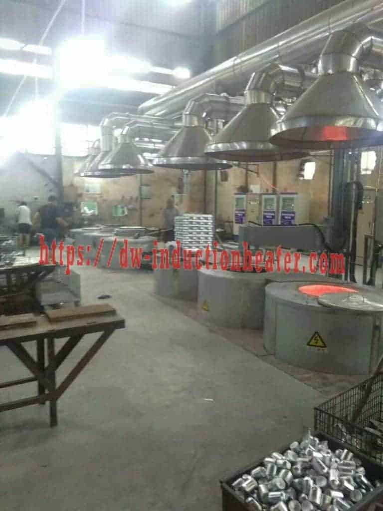
Published crucible dimensions
A is the upper-mouth outside diameter, B the upper-mouth inside diameter, C the bottom outside diameter and H the overall height. Dimensions are in millimetres; published tolerances are A ±10 mm, B ±5 mm, C ±10 mm and H ±10 mm. These are crucible dimensions, not furnace footprint or installation clearances.
| Model | Crucible designation | A (mm) | B (mm) | C (mm) | H (mm) |
|---|---|---|---|---|---|
| SMJD-463 | 463# | 565 | 500 | 310 | 617 |
| SMJD-480 | 480# | 510 | 420 | 400 | 710 |
| SMJD-580 | 580# | 420 | 360 | 300 | 840 |
| SMJD-600 | 600# | 620 | 525 | 620 | 470 |
| SMJD-900 | 900# | 520 | 425 | 510 | 960 |
| SMJD-905 | 905# | 620 | 530 | 620 | 650 |
| SMJD-1250 | 1250# | 620 | 535 | 620 | 850 |
| SMJD-1500 | 1500# | 735 | 640 | 460 | 900 |
| SMJD-1550 | 1550# | 775 | 682 | 400 | 750 |
| SMJD-1700 | 1700# | 610 | 500 | 610 | 1200 |
| SMJD-2300 | 2300# | 880 | 775 | 355 | 1000 |
| SMJD-3100 | 3100# | 780 | 645 | 780 | 1400 |
Topology, frequency and power supply options
| Item | Published information |
|---|---|
| Circuit topology on this product page | Series connection — the compensating capacitor is in series with the load, in one current path through generator, capacitor, load and coil |
| Parallel topology HLQ also publishes | On the current-inverting medium-frequency generators, a parallel oscillating circuit is realised by the current-inverting technology, using soft-switching resonance dual-control and frequency tracking; that parallel circuit gives the medium-frequency series generator its characteristics |
| Oscillation frequency, SMJD | 1–100 kHz, customised according to the customer request |
| Oscillation frequency, MF line | 1–20 kHz, normally about 4, 8, 11, 15 or 20 kHz depending on the application |
| Frequency selection method | The working frequency is designed by changing the coil and the compensating capacitor according to the melting material, quantity, stirring effect, working noise and melting efficiency |
| Frequency selection by metal and batch | Low frequencies, tens to a few hundred Hz, give deeper penetration for larger batches and suit lead and zinc; medium frequencies in the kHz range suit faster melting of smaller batches and for tin |
| Load matching | Digital PLL frequency tracking with automatic load impedance matching |
| Output control | Constant output voltage or constant output power modes, with display of output power, frequency, voltage and current |
| Heating curve control | Timer presets for heating time, heating power, retaining time and retaining power, to control the heating curve and temperature |
| Machine set | Medium-frequency generator, compensating capacitor and melting furnace; infrared temperature sensor and temperature controller can be included if ordered |
| Furnace body types | Tilting (manual, electrical, hydraulic), push-up and stationary |
| Crucible designs for the low-melting-point metals | Tilting crucible, bottom-pour or lift-out, to match the casting or tapping requirement; graphite, magnesia or alumina selected on the metal chemistry and the life cycle |
| Atmosphere options | Covered crucibles, inert gas purging or simple flux dosing, to reduce dross and improve yield on the oxidation-sensitive melts |
| Control | PLC or touchscreen with programmable heating ramps, setpoints and alarms |
| Cooling | Closed-loop water cooling tower or industrial chiller, for the coil, capacitors and cables |
| Safety | Interlocks, emergency stop, over-temperature protection and fume capture interfaces |
Original technical resources: SMJD induction melting furnace parameter sheet and Aluminum, Copper and Iron Induction Melting Furnace manual.

Recommended Model Selection
Selection for this furnace runs in three steps: the duty, the metal, and the batch. The published reference ladder below is the starting point.
| Operation type | Recommended power density (kW/t) | Notes |
|---|---|---|
| Rapid batch melting (ingot charge) | 450 – 600 | Maximum melting speed; shortest cycle time |
| Standard batch melting (mixed charge) | 350 – 450 | Balanced speed and energy efficiency |
| Scrap remelting (variable density) | 300 – 400 | Lower density scrap; longer effective cycle |
| Continuous casting (melting + holding) | 250 – 350 | Steady-state supply to the casting machine |
| Holding and temperature maintenance | 100 – 200 | Compensating for heat losses only |
The published application ladder by capacity and power:
| Application | Material | Recommended power | Frequency |
|---|---|---|---|
| Laboratory aluminum melting | Pure aluminum, small alloy samples | 15–30 kW | 10–20 kHz |
| Small jewelry or sample casting | Aluminum alloy, small ingots | 25–60 kW | 8–20 kHz |
| 50–100 kg workshop melting | Aluminum ingots, clean scrap | 60–120 kW | 4–10 kHz |
| 150–300 kg aluminum foundry furnace | Aluminum alloy, casting returns | 120–250 kW | 2–8 kHz |
| 300–500 kg hydraulic tilting furnace | Aluminum ingots, scrap, runners | 200–400 kW | 1–6 kHz |
| 500–1000 kg aluminum recycling furnace | Aluminum scrap, profile scrap, clean returns | 350–800 kW | 0.8–4 kHz |
| 1–2 ton industrial aluminum melting | Aluminum alloy, recycled aluminum | 700–1500 kW | 0.5–3 kHz |
| 2–5 ton large aluminum melting line | Aluminum scrap, ingots, foundry returns | 1200–3000 kW | 0.5–2 kHz |
For the wider capacity range across the low-melting-point non-ferrous family, HLQ publishes a dedicated induction melting furnace for lead, tin and zinc covering 100–5,000 kg batches, and the 300 kW medium-frequency induction heating power supply for the published parallel-circuit generator specification. For a specific four-capacity set published as a page of its own — the 300 kg, 500 kg, 800 kg and 1200 kg entries — see the 300 kg, 500 kg, 800 kg and 1200 kg aluminium induction melting furnace.
Process Workflow
The melting sequence, followed by the keep-warm phase that this furnace is also used for. This is the published aluminium melting workflow with the holding step made explicit.
| Step | Action | Control point |
|---|---|---|
| 1. Pre-operation inspection | Check the power supply, cooling water, crucible condition, hydraulic system, electrical protection and emergency stop | Everything that can stop the cell before it starts |
| 2. Crucible preheating | Preheat the crucible gradually if required, especially for a new crucible or after a long shutdown | Avoids thermal shock |
| 3. Charge preparation | Clean, dry and sort the charge by alloy; remove oil, water and cutting fluid | No water, oil or sealed cavities in the charge |
| 4. Charging | Load dense material first; add more charge as the first batch melts, within the safe filling limit | Correct charge order |
| 5. Melting | Increase power gradually, then hold at full power with electromagnetic stirring active | Power and time |
| 6. Fluxing and dross removal | Apply suitable refining flux if required and remove dross from the surface | Melt cleanliness |
| 7. Temperature measurement | Check the melt with a suitable probe or sensor | Measurement method and calibration |
| 8. Alloying | Add alloying materials and master alloys as required | Composition before the hold |
| 9. Keep warm | Reduce power and maintain the metal at the required pouring temperature | Holding power density is published at 100–200 kW/t |
| 10. Pouring | Tilt into a ladle, mould or holding furnace at the pouring temperature | Pouring temperature and alignment |
| 11. Cleaning and shutdown | Remove residual dross, inspect the crucible and follow the shutdown procedure | Lining wear and the per-shift record |
| 12. Records | Record melting time, energy consumption, lining condition and alarms | Per-heat traceability |


Common Problems and Solutions
| Problem | What to investigate | Response |
|---|---|---|
| Melting speed is too slow | Power too low, charge too large, poor crucible condition or low coupling efficiency | Increase power, optimize the charge size, check the crucible and confirm the correct furnace capacity. |
| Excessive dross formation | Overheating, dirty scrap, thin aluminium cans, excessive stirring or long holding time | Control the temperature, clean and sort the scrap, reduce the holding time and use proper fluxing practice. |
| Dross and burning loss with aluminium | Thin, dirty or coated scrap; excessive temperature | Clean and dry the charge, control the temperature and use a proper flux or cover. |
| Molten metal contamination | Mixed scrap, dirty charge, wrong flux, damaged crucible or tool contamination | Sort the materials, clean the charge, use dedicated tools and maintain the crucible condition. |
| Oxidation on zinc and tin | An uncovered crucible and an open atmosphere | Use a covered crucible, inert gas purging or simple flux dosing to reduce dross and improve yield. |
| Coil overheating | Insufficient cooling water, scale blockage, water pump failure or high inlet temperature | Check the flow rate, clean the cooling circuit, maintain the pump and use a closed-loop cooling system. |
| Temperature is unstable during the hold | Poor temperature measurement, unstable power, uneven charging or excessive heat loss | Use a reliable temperature probe, stabilize the power supply, improve insulation and standardize the charging. |
| Frequency or matching fault | Load change against the capacitor bank, or a tracking fault | Confirm the frequency and capacitor bank against the confirmed furnace, and check the automatic tracking and load matching. |
| Crucible cracks | Thermal shock, poor preheating, mechanical impact or wrong crucible material | Preheat gradually, avoid dropping charge, select the correct crucible and follow the supplier’s instructions. |
| Violent eruption when charging | Wet, oily or sealed scrap | Charge only clean, dry material and remove sealed cavities. |
| Pouring is unstable | Hydraulic system problem or poor ladle and furnace alignment | Inspect the tilting mechanism, the hydraulic system and the pouring layout. |
Engineering Selection Guide
Work through these in order. The table states what has to be established and what the published data does and does not settle.
| Factor | What to confirm | Engineering recommendation |
|---|---|---|
| Duty | Melting only, melting with a keep-warm phase, or continuous supply | Sets the power density. Melting is published at 350–450 kW/t for a mixed charge and 300–400 kW/t for scrap; holding is 100–200 kW/t; continuous casting is 250–350 kW/t. |
| Metal | Aluminium, zinc, tin, lead or another low-melting-point alloy | Sets the crucible, the atmosphere and the operating temperature. Zinc and tin both need a covered crucible or inert gas. |
| Frequency | The required operating frequency | Low frequencies for deeper penetration into larger batches and for lead and zinc; medium frequencies for faster melting of smaller batches and for tin. Confirm the frequency and the capacitor bank for the ordered furnace. |
| Topology | Series connection or the parallel oscillating circuit | Both are published. The circuit name does not set the power — confirm it on the quotation. |
| Batch capacity | Required kilograms per heat | Select the capacity with a reasonable margin for production demand. |
| Hold duration | How long the melt is held at the pouring temperature | No holding time is published for any model. Agree it as part of the specification, and size the installation against the 100–200 kW/t holding figure rather than the melting figure. |
| Pouring method | Manual, electrical or hydraulic tilting | Hydraulic tilting is recommended for medium and large furnaces. |
| Crucible and body type | Graphite, magnesia or alumina; tilting, bottom-pour or lift-out | Selected on the metal chemistry, the life cycle and the casting or tapping requirement. |
| Atmosphere | Open air, covered crucible, inert gas or flux dosing | Required for zinc and tin. Reduces dross and improves yield. |
| Electrical supply | Plant voltage, transformer capacity, cable size | Confirm the transformer and cable capacity before installation, and confirm the reconciled output and input ratings. |
| Cooling | Water flow, pressure, temperature and quality | Closed-loop cooling tower or industrial chiller for stable long-term operation. |
| Layout | Charging area, crane, ladle path, mould area, fume capture | Plan the layout before fixing the furnace dimensions. |
Two items remain open and should be closed before the order is placed. The published frequency range is a statement of capability rather than a setting, so the operating frequency and the capacitor bank have to be confirmed against the confirmed furnace. And no holding time, holding temperature or throughput is published for any model in this family, so those three figures have to be agreed as part of the specification rather than assumed from the capacity.
Advantages and Limitations
| Aspect | Potential benefit | Boundary |
|---|---|---|
| One furnace, two duties | Melting and keeping warm on the same machine, with published holding density of 100–200 kW/t | No holding time or holding temperature is published, so the hold has to be specified and measured. |
| Heat generated in the charge | Fast, clean, uniform melting with no combustion product at the melt | Charge contaminants still create fumes; electrical operation does not establish zero emissions. |
| Electromagnetic stirring | Mixes the melt and floats flux and oxides for cleaner castings | Excessive stirring also increases oxidation, so it is a balance rather than a benefit to maximise. |
| Automatic tracking and matching | The tank stays matched as the load changes through the melt and into the hold | The capacitor bank is sized as part of the order; the circuit name does not set the power. |
| Continuous operation | 100 % load duration at maximum power for 24 hours, which is what makes a long hold practical | No model-specific continuous-duty test conditions are published. |
| Low-melting-point metals | One platform covers aluminium, zinc, tin and lead | Crucible, atmosphere and frequency change with the metal, and zinc and tin both need a covered crucible or inert gas. |
| Temperature control | PID holding with an LED controller accurate to up to 3 °C | Actual accuracy depends on the confirmed measurement system and its calibration. |
| Energy | Published as 20–40 % against a diesel-fired workshop furnace, and 20–30 % against gas and oil in the manual | The two published figures differ and neither is a guaranteed saving without a defined baseline and measured cycle data. |
Published for the induction melting range generally: fast, clean and uniform melting with the heat produced in the charge; electromagnetic stirring that mixes the alloy; no burner or combustion gas in contact with the melt; temperature set by the power supply and easy to control; and a capacity range from 0.5 kg to 5,000 kg. Against those advantages sit the published limitations: a large electrical supply is needed for big furnaces, the refractory lining is a consumable that must suit the metal, continuous cooling water is required, the charge must be dry and clean for safety, and highly volatile alloys need fume extraction.
One boundary is specific to this duty. A hold is the cheapest phase of the cycle and the easiest one to waste: the published holding density is a fraction of the melting density, so every extra hour held is electricity spent at a low rate that still adds up, and for aluminium it adds oxidation on top. That is why the hold duration belongs in the specification rather than in the operating habit.

Why Choose HLQ?
HLQ Induction Equipment publishes the model capacity table, the electrical parameter sheet with crucible dimensions, the melting furnace manual and the technical references for the low-melting-point non-ferrous range. That body of published data is the practical reason to specify from this range: the furnace, the coil, the capacitor bank, the crucible, the lining, the control, the cooling and the protection are documented as one matched system rather than sold as a bare box.
For a project with a keep-warm phase, two published details matter more than the catalogue capacity. The published load duration of 100 % at maximum power over 24 hours is what makes a long hold physically possible, and the published holding power density of 100–200 kW/t is what makes it affordable — together they tell you the installation size before you ask. The company’s wider engineering reference, covering power supply manufacturing, coil design and process development, sits on the induction furnace page.
Other original listings on this topic: Al melting furnace with induction, aluminum melting crucible furnace and 300 kW medium-frequency induction heating power supply. These are separate product listings with their own specifications, not interchangeable data for this furnace.
Original product topic links: aluminum melting furnace · induction melting furnace · medium frequency melting furnace · aluminum smelting furnace · aluminum melting oven

6 Core FAQs
1. What does “series connection” actually mean on this furnace?
It describes where the compensating capacitor sits in the resonant tank. In the series-connected arrangement the capacitor is in series with the load, so one current path runs through the generator, the capacitor, the load and the coil. HLQ also publishes a parallel oscillating circuit on its current-inverting medium-frequency generators, using soft-switching resonance dual-control and frequency tracking. Both are legitimate; the practical consequence of the series arrangement is that the capacitor bank is sized as part of the furnace order, the frequency is tracked automatically as the load changes, and the impedance matching is automatic as the bath settles. Confirm which topology is being quoted — the circuit name does not set the power.
2. What aluminium capacity is published, and is it 100 kg or 150 kg?
150 kg to 1,200 kg per heat. The published table’s header is offset, so the aluminium figure is the third numeric column in each row; the smallest listed entry is SMJD-480 at 150 kg and the largest is SMJD-3100 at 1,200 kg, on 60 kW to 200 kW models. The middle column, 500–3,000 kg, is the copper, gold and silver (scrap, slag) figure. This page previously advertised “100^1200kg”; the source table’s smallest aluminium entry is 150 kg, and no 100 kg model is published in the SMJD series.
3. Can one furnace both melt and keep warm?
Yes, and that is the duty this page is written around. Melting runs at full rated power, at a published density of 350–450 kW/t for a standard mixed charge and 300–400 kW/t for scrap. The keep-warm phase reduces the power to hold the melt at the pouring temperature, at a published 100–200 kW/t — the figure to size the electrical installation against for a hold duty. Published load duration is 100 % at maximum power for 24 hours, which is what makes a long hold practical. What is not published is a holding time or a holding temperature for any model, so those have to be agreed as part of the specification.
4. Which metals are suited to this furnace, and what changes between them?
Aluminium, zinc, tin and lead — the low-melting-point non-ferrous family. Pure aluminium melts at about 660 °C and is held at 680–760 °C. Zinc and tin are both susceptible to oxidation, so covered crucibles, fluxes or an inert gas environment reduce dross and improve yield. Frequency follows the metal and the batch: low frequencies give deeper penetration for larger batches and suit lead and zinc, while medium frequencies suit faster melting of smaller batches and for tin. The crucible is matched to the metal chemistry and the life cycle — graphite, magnesia or alumina, in a tilting, bottom-pour or lift-out body.
5. What frequency should the furnace run at?
The published SMJD range is 1–100 kHz, customised according to the customer’s request, and the published medium-frequency line is 1–20 kHz, normally about 4, 8, 11, 15 or 20 kHz depending on the application. HLQ’s published method is that the working frequency is designed by changing the coil and the compensating capacitor according to the melting material, quantity, stirring effect, working noise and melting efficiency. For aluminium the published guidance is about 0.5–20 kHz, with the lower frequency used for the larger furnaces. Treat the range as a statement of capability, not a setting — confirm the operating frequency and the capacitor bank for the ordered furnace.
6. What is not published about this furnace?
Several things a buyer should know are open. There is no holding time and no holding temperature for any model. There is no kg/h throughput and no model-specific melting time for the SMJD series. There is no recovery rate for a scrap duty. And the published power and current figures do not reconcile at 380 V — the published kW divided by the apparent power at the published current is 1.013 in every row — so the transformer, incomer and power cabling must be sized from confirmed ratings rather than from the table. All of these are specification items to close before the order is placed, not figures to infer.