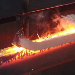


RF Induction Heating Equipment
DW-HF-90KW RF Induction Heating Equipment for Brazing, Hardening and Metal Heat Treatment
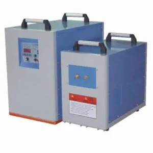
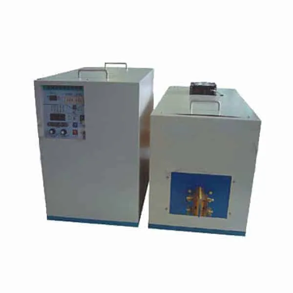
The HLQ DW-HF-90KW RF Induction Heating Equipment is a high-frequency industrial induction heating system designed for localized metal heating, induction brazing, surface hardening, annealing and selected forging applications.
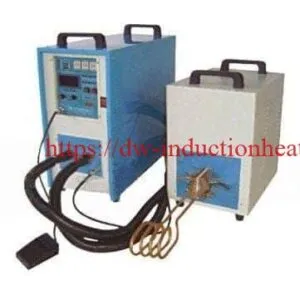
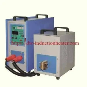
The equipment uses IGBT inverter technology and a separated power generator and output transformer arrangement to deliver high-frequency electrical energy to a matched induction heating coil.
The DW-HF-90KW has a published maximum oscillation rating of 90 kVA, an operating frequency range of 30–80 kHz and a three-phase 380 V, 50/60 Hz input supply.
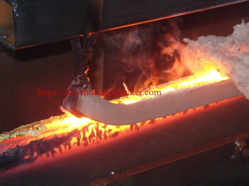
Typical applications include copper and brass tube brazing, diamond tool brazing, gear and shaft heat treatment, localized metal annealing and heating steel rods for forming operations.
Important technical clarification: The published 90 kVA oscillation rating is not equivalent to a verified 90 kW of useful thermal power absorbed by the workpiece. Actual heating performance depends on generator output characteristics, coil design, material properties and electromagnetic coupling.
Quick Answer
What is the DW-HF-90KW RF Induction Heating Equipment?
The HLQ DW-HF-90KW is a high-frequency induction heater designed to generate localized heat inside electrically conductive metals. It uses an IGBT-based power generator, a separate output transformer and an application-specific induction coil.
The system operates within a published frequency range of 30–80 kHz and has a maximum oscillation rating of 90 kVA. It is designed for three-phase 380 V, 50/60 Hz electrical input and requires water cooling.
Main applications: industrial induction brazing, copper tube brazing, tool brazing, gear and shaft surface hardening, metal annealing, localized heat treatment and selected rod-end heating operations.
Model selection: DW-HF-90KW is most appropriately evaluated for industrial heating processes requiring high-frequency electromagnetic coupling and a relatively concentrated heating zone. The final suitability depends on workpiece dimensions, heating depth, required temperature and production cycle.
Engineering caution: The equipment’s published rating does not independently establish the heating time, melting capacity, hardening depth or production throughput of a particular application.
Table of Contents
- What is the DW-HF-90KW RF Induction Heating Equipment?
- Key Applications
- Suitable Materials
- Working Principle
- Technical Specifications
- Recommended Model Selection
- Process Workflow
- Common Problems and Solutions
- Engineering Selection Guide
- Advantages and Limitations
- Why Choose HLQ?
- 10 Core FAQs
What is the DW-HF-90KW RF Induction Heating Equipment?
The DW-HF-90KW RF Induction Heating Equipment is an industrial electromagnetic heating system that converts three-phase electrical power into high-frequency electrical energy.
This energy is supplied to a specially designed induction coil positioned around or near a conductive metal workpiece.
When high-frequency alternating current passes through the coil, it creates an alternating magnetic field. The field induces electrical currents within the metal, producing heat through electrical resistance.
Unlike conventional external heating methods, induction heating generates energy directly within electrically conductive material.
The heating pattern can be concentrated around a specific joint, surface or section of a workpiece, depending on the induction coil design.
Main Equipment Components
| Component | Function | Engineering Consideration |
|---|---|---|
| IGBT Power Generator | Converts industrial electrical input into high-frequency output power. | Rated input, output characteristics, operating frequency and duty cycle. |
| Separated Output Transformer | Transfers high-frequency energy to the induction heating circuit. | Electrical matching, current capacity and connection configuration. |
| Induction Heating Coil | Generates an alternating magnetic field around the workpiece. | Coil diameter, turns, clearance, geometry and cooling. |
| Cooling Water Circuit | Removes heat from designated electrical and coil components. | Flow rate, pressure, temperature and water quality. |
| Heating Control System | Provides control of selected operating parameters. | Power control, current regulation and optional timing functions. |
| Electrical Protection System | Monitors selected abnormal operating conditions. | Overcurrent, overvoltage, phase faults and cooling failure. |
| Output Connection Cable | Connects the generator arrangement and output assembly. | Published 2 m connection length and electrical matching. |
What Makes the DW-HF-90KW Different?
The DW-HF-90KW belongs to HLQ’s high-frequency induction heating equipment category.
Its published operating frequency of 30–80 kHz makes it suitable for evaluation in applications requiring localized heating of metal joints, surfaces and selected component sections.
The equipment uses a separated generator and output unit arrangement.
This configuration can make it easier to position the output transformer near a heating station while locating the main generator in a more suitable operating area.
The machine also supports different induction coil shapes for different workpiece geometries.
High-Frequency Induction Heating vs. Medium-Frequency Heating
| Comparison | High-Frequency Induction Heating | Medium-Frequency Induction Heating |
|---|---|---|
| Frequency | Higher operating frequency. | Lower operating frequency. |
| Electromagnetic Penetration | Generally more concentrated near the surface at equivalent material conditions. | Generally deeper electromagnetic penetration. |
| Typical Applications | Brazing, surface hardening, localized annealing and small-section heating. | Billet forging, deeper heating, large-section processing and melting. |
| Induction Coil | Designed for relatively concentrated heating regions. | Designed according to larger thermal loads or deeper heating needs. |
| Equipment Selection | Material, heating area, coupling and frequency requirements. | Material thickness, thermal mass and required penetration. |
The correct frequency cannot be determined solely from nominal power. Workpiece geometry, magnetic properties, electrical resistivity and the heating process must also be considered.
Key Applications
The DW-HF-90KW can be evaluated for multiple industrial metal-heating applications when the generator, induction coil and process controls are appropriately configured.
1. Induction Brazing of Copper and Brass Tubes
Induction brazing is a process in which the joint area of two components is heated until a selected brazing filler metal melts and flows into the joint.
The base metals are normally not melted during the brazing process.
High-frequency induction heating can be used for copper tubes, brass fittings and selected dissimilar-metal assemblies.
Typical applications include:
- Copper tube to copper fitting brazing.
- Copper tube to brass connector brazing.
- HVAC refrigeration pipe brazing.
- Heat exchanger tube connections.
- Industrial copper piping assemblies.
- Selected stainless-steel-to-copper brazed joints.
The heating process must be matched to the joint dimensions, filler alloy, flux or protective atmosphere and the required brazing temperature.
For detailed application information, see induction brazing copper tubes.
2. Induction Brazing of Diamond Tools
Diamond cutting tools and industrial tool segments may require controlled brazing to attach suitable cutting elements to metallic holders.
Induction heating can concentrate energy near the brazing interface, allowing the joint to be heated without necessarily heating the entire tool assembly to the same temperature.
Successful brazing depends on filler-metal selection, bonding characteristics, temperature control and the thermal sensitivity of the tool material.
Explore the related induction brazing diamond tools application.
3. Gear and Shaft Surface Hardening
Induction hardening is a localized heat-treatment process used to increase the surface hardness and wear resistance of suitable steels.
The workpiece surface is heated to an appropriate austenitizing temperature and then quenched using a selected cooling medium.
The required heating temperature, quench rate and hardening depth depend on the material grade, original microstructure and mechanical performance requirements.
Potential applications include:
- Steel shaft surface hardening.
- Gear tooth and gear-ring hardening.
- Machine spindle hardening.
- Selected bearing surfaces.
- Industrial pins and mechanical components.
For automated or production-oriented applications, see shaft induction hardening equipment.

4. Localized Metal Annealing
Induction annealing is used to modify selected material properties through a controlled heating and cooling process.
Depending on the material, annealing may reduce hardness, improve ductility or modify residual stresses and microstructure.
Potential workpieces include steel tubes, stainless-steel components, brass fittings, copper assemblies and other conductive materials.
The induction power supply must be matched to the annealing temperature, required heating depth and thermal cycle.
For further engineering information, see the induction annealing process guide.
5. Heating Steel Rods for Forging
Induction heating can raise the temperature of a selected steel rod or bar section before mechanical deformation.
Typical forming operations include upsetting, heading, bending and selected die-forging applications.
For small and medium cross-sections, high-frequency induction equipment may be considered after evaluating the required heating depth and cycle time.
For larger bars or applications requiring more uniform through-heating, lower-frequency induction equipment may be more appropriate.
See the related induction forging bar ends applications.
6. Heating Metal Components Before Shrink Fitting
Induction heating can be used to expand selected metallic components before assembly.
Components such as rings, hubs, bushings and couplings may be heated to produce sufficient thermal expansion for an interference-fit assembly.
Heating requirements depend on the component material, dimensional interference, coefficient of thermal expansion and maximum allowable temperature.
7. Selected Small Metal Melting Applications
Induction equipment can be used for metal melting when the generator, induction coil, crucible and cooling system are designed for the specific melting process.
However, the DW-HF-90KW’s published specifications do not establish a universal melting capacity or confirm compatibility with every metal.
The suitability of a melting application must be evaluated according to metal type, charge mass, melting temperature, crucible design and electromagnetic coupling.
Application Suitability Comparison
| Application | Typical Material | Heating Objective | Key Selection Factor |
|---|---|---|---|
| Copper Tube Brazing | Copper and Brass | Heat the joint to the filler-metal flow temperature. | Joint geometry and coil design. |
| Diamond Tool Brazing | Metal Holder and Tool Segment | Controlled brazing at the interface. | Filler alloy and thermal sensitivity. |
| Gear Hardening | Medium-Carbon or Alloy Steel | Local surface austenitization. | Material and required case depth. |
| Shaft Hardening | Carbon Steel or Alloy Steel | Heat selected shaft surfaces before quenching. | Diameter, heating pattern and quench design. |
| Metal Annealing | Steel, Brass, Copper | Controlled thermal treatment. | Temperature profile and material condition. |
| Rod-End Forging | Steel, Brass or Copper | Localized heating before forming. | Cross-section and heating depth. |
| Shrink Fitting | Steel or Other Conductive Metals | Produce controlled thermal expansion. | Required assembly clearance. |
| Small Metal Melting | Application-Specific | Raise charge temperature above the melting point. | Coil, crucible, frequency and charge mass. |
Suitable Materials
Induction heating requires an electrically conductive material.
The heating characteristics of a metal depend on its electrical resistivity, magnetic permeability, thermal conductivity, specific heat capacity and geometry.
Ferromagnetic carbon steels can provide strong electromagnetic coupling below their Curie temperature.
Nonferrous metals such as copper, brass and aluminum can also be induction heated, although their different electrical and thermal properties require appropriate coil and generator matching.
Material Compatibility Table
| Material | Typical Application | Compatibility Consideration |
|---|---|---|
| Low-Carbon Steel | Preheating and Localized Heating | Generally favorable induction coupling; final process depends on the application. |
| Medium-Carbon Steel | Surface Hardening and Forging | Suitable steel grades may respond to induction hardening. |
| Alloy Steel | Hardening and Heat Treatment | Heating temperature and cooling must be matched to the alloy. |
| Stainless Steel | Brazing and Annealing | Magnetic properties and temperature-dependent behavior affect coupling. |
| Copper | Tube Brazing and Assembly Heating | High conductivity and heat transfer require appropriate coil matching. |
| Brass | Brazing and Forming | Heating temperature depends on the alloy and process. |
| Aluminum | Selected Heating Applications | Requires application-specific electrical and thermal evaluation. |
| Cast Iron | Localized Heating | Thermal stress and cracking risks must be evaluated. |
| Carbide Tool Assemblies | Tool Brazing | Joint heating and thermal sensitivity require attention. |
| Plastic or Ceramic Alone | Not Directly Heated by Conventional Induction | Requires a conductive susceptor or another suitable heating method. |
How Material Properties Affect Heating
| Material Property | Effect on Induction Heating | Engineering Response |
|---|---|---|
| Electrical Resistivity | Influences induced current and resistance heating. | Select suitable power and operating frequency. |
| Magnetic Permeability | Influences magnetic coupling and electromagnetic penetration. | Consider magnetic behavior at process temperature. |
| Thermal Conductivity | Controls how quickly heat moves away from the heated zone. | Account for conduction losses and local temperature gradients. |
| Specific Heat Capacity | Determines the energy needed for temperature increase. | Calculate workpiece thermal mass. |
| Material Thickness | Influences penetration requirements and heating time. | Review coil design and frequency suitability. |
| Heat Treatment History | May affect metallurgical response to additional heating. | Use an appropriate process specification. |
Working Principle
How Does RF Induction Heating Work?
RF induction heating operates through electromagnetic induction.
The power generator converts standard industrial AC electricity into high-frequency electrical energy.
This energy is supplied to an induction coil, producing a rapidly alternating magnetic field.
When an electrically conductive metal is placed within the field, electrical currents are induced inside the workpiece.
These currents generate heat due to the electrical resistance of the material.
The magnitude and distribution of heating depend on the electromagnetic properties of the metal, the frequency, the induction coil geometry and the applied power.
RF Induction Heating Process
| Stage | Process | Result |
|---|---|---|
| 1 | Three-Phase Electrical Input | Electrical energy enters the power generator. |
| 2 | Power Conversion | The IGBT inverter produces high-frequency electrical output. |
| 3 | Output Transformer and Matching | Power is delivered to the resonant heating circuit. |
| 4 | Induction Coil Energization | A rapidly alternating magnetic field is generated. |
| 5 | Eddy Current Generation | Electrical currents form inside the conductive metal. |
| 6 | Resistance Heating | Electromagnetic energy is converted into thermal energy. |
| 7 | Process Control | Heating power and time are controlled according to the equipment configuration. |
| 8 | Process Completion | The workpiece undergoes brazing, hardening preparation or another thermal operation. |
How Does Frequency Affect Heating Depth?
The distribution of induced electrical current depends partly on the operating frequency.
At higher frequencies, current generally becomes more concentrated near the surface of a conductive workpiece.
The characteristic electromagnetic penetration depth is commonly described using the skin-depth relationship:
δ = √(2ρ / ωμ)
Where:
- δ = electromagnetic skin depth, m.
- ρ = electrical resistivity, Ω·m.
- ω = angular frequency, rad/s.
- μ = magnetic permeability, H/m.
The equation is a simplified electromagnetic relationship and does not directly establish the final hardened case depth or the total depth reached by heat conduction.
For ferromagnetic steel, magnetic permeability changes with temperature, particularly near the Curie temperature. As a result, the actual heating process must account for temperature-dependent material behavior.
Important Factors Affecting Heating Performance
| Factor | Influence | Engineering Consideration |
|---|---|---|
| Induction Frequency | Affects induced current distribution. | Match the operating frequency to the material and heating requirement. |
| Coil Design | Controls magnetic-field geometry. | Use a coil designed for the workpiece. |
| Coil Clearance | Influences electromagnetic coupling. | Maintain suitable coil-to-workpiece spacing. |
| Workpiece Geometry | Determines heating distribution and thermal mass. | Review diameter, length, wall thickness and shape. |
| Heating Time | Determines accumulated energy and heat conduction. | Establish the required thermal cycle. |
| Power Regulation | Influences heating rate. | Use appropriate process settings. |
| Cooling System | Protects designated equipment components. | Verify cooling flow, pressure and temperature. |
| Material Properties | Change heating behavior with temperature. | Evaluate the complete temperature range. |
Technical Specifications
The following table reproduces the published technical parameters of the HLQ DW-HF-90KW RF Induction Heating Equipment.
Some values require additional manufacturer confirmation because the original page does not provide complete measurement conditions or definitions.
DW-HF-90KW Main Technical Parameters
| Technical Parameter | Published Specification | Engineering Notes |
|---|---|---|
| Equipment Model | DW-HF-90KW | High-frequency RF induction heating equipment. |
| Input Voltage | 3 × 380 V | Three-phase supply. |
| Input Frequency | 50–60 Hz | Industrial electrical supply. |
| Maximum Oscillation Rating | 90 kVA | Not equivalent to verified useful heating power in kW. |
| Maximum Input Apparent Power | 99 kVA | Actual input kW and power factor require confirmation. |
| Oscillation Frequency | 30–80 kHz | Operating point depends on load and resonant matching. |
| Oscillating Current | 30–160 A | Refers to the published oscillating circuit current, not mains input current. |
| Cooling Water Parameter | 0.3 MPa | The pressure limit and operating range require clarification. |
| Published Minimum Cooling Flow | 6 L/min | Verify cooling conditions for the complete system. |
| Published Duty Cycle | 100% at 30°C | Conditional on appropriate cooling and operating requirements. |
| Listed Weight | 110 kg | Confirm whether the value refers to the complete system. |
| Main Generator Dimensions | 650 × 350 × 455 mm | Published cabinet dimensions. |
| Extension Unit Dimensions | 700 × 350 × 450 mm | Published output-unit dimensions. |
| Connection Cable Length | 2 m | Verify permitted cable configurations. |
| Power Conversion | IGBT Inverter | Published equipment technology. |
| Cooling Method | Water Cooling | Applicable components and circuit details require confirmation. |
Power and Control Features
| Feature | Published Function | Engineering Interpretation |
|---|---|---|
| IGBT Inverter Technology | High-frequency power conversion. | Actual conversion efficiency is not specified. |
| Constant Current Mode | Selectable operating-control mode. | Suitable configuration depends on the heating load. |
| Constant Power Mode | Selectable operating-control mode. | Requires clarification of the controlled power parameter. |
| Power Display | Display of selected heating power parameters. | Actual measurement accuracy requires confirmation. |
| Current Display | Heating or oscillating current indication. | Must not be confused with mains input current. |
| Frequency Display | Displays operating oscillation frequency. | Useful for tuning and monitoring. |
| Timer Functions | Available on timer-equipped configurations. | Confirm inclusion in the supplied model. |
| Fault Indication | Selected electrical and cooling alarms. | Protection details depend on equipment configuration. |
| Separated Output Unit | Generator and output assembly arrangement. | Facilitates positioning around the production station. |
Electrical Installation Requirements
The power supply must be designed using verified electrical input data.
For a balanced three-phase system, apparent electrical power is approximately:
S = √3 × V × I / 1000
Where:
- S = three-phase apparent power, kVA.
- V = line-to-line voltage, V.
- I = line current, A.
Using the published maximum input apparent power of 99 kVA at 380 V:
I = 99,000 / (√3 × 380)
Calculated current ≈ 150.4 A
This is an arithmetic calculation based on the published apparent-power rating. It is not a certified maximum input current, a circuit-breaker recommendation or a substitute for the manufacturer’s electrical installation drawing.
Final installation must account for actual input current, power factor, protective devices, conductor sizing, earthing and applicable electrical codes.
Cooling Water Requirements
| Cooling Parameter | Published Information | Recommended Verification |
|---|---|---|
| Cooling Water Pressure | 0.3 MPa | Confirm whether this is a maximum, nominal or recommended pressure. |
| Cooling Water Flow | At least 6 L/min | Confirm the required flow through each cooled circuit. |
| Water Inlet Temperature | Not Specified | Obtain the permitted range. |
| Maximum Outlet Temperature | Not Specified | Confirm equipment thermal limits. |
| Water Quality | Not Specified | Confirm conductivity and water-treatment requirements. |
| Required Cooling Capacity | Not Specified | Determine from actual system heat rejection. |
| Cooling-System Type | Water-Cooled Equipment | Confirm whether an external chiller is included or required. |
Cooling water must be available and verified before energizing the induction heating equipment.
Recommended Model Selection
The correct induction heating equipment should be selected according to the workpiece, heating process and production requirements.
Although the DW-HF-90KW is identified by a 90KW model designation, the published electrical specification uses kVA for the oscillation rating.
Model selection should therefore be based on confirmed electrical and thermal performance rather than assuming that the model number represents useful thermal power.
DW-HF-90KW Application Selection Guide
| Application | Preliminary Suitability | Critical Engineering Requirement |
|---|---|---|
| Copper Tube Brazing | Potentially Suitable | Joint geometry, filler alloy, coil and heating time. |
| Brass Fitting Brazing | Potentially Suitable | Joint mass and suitable brazing temperature. |
| Diamond Tool Brazing | Potentially Suitable | Tool material and bonding temperature. |
| Medium-Carbon Steel Shaft Hardening | Potentially Suitable | Shaft diameter, case depth and quench system. |
| Gear Surface Hardening | Application-Specific | Gear geometry, tooth profile and hardening pattern. |
| Localized Annealing | Potentially Suitable | Required temperature and thermal history. |
| Small Rod-End Heating | Application-Specific | Rod diameter, heating depth and cycle time. |
| Large Billet Through-Heating | Lower-Frequency Equipment May Be Preferable | Cross-section, penetration and productivity. |
| Large Metal Melting Furnace | Not Established by Published Data | Melting capacity, crucible design and frequency requirements. |
High-Frequency Model Comparison
The following comparison provides general engineering guidance based on the neighboring HLQ high-frequency product series. It should not be interpreted as a certified specification table for every production revision.
| Model Family | Published Nominal Rating | Preliminary Application Focus |
|---|---|---|
| DW-HF-45 Series | 45 kVA | Smaller brazing and localized metal-heating requirements. |
| DW-HF-60 Series | 60 kVA | Medium industrial brazing and selected heat-treatment applications. |
| DW-HF-90 Series | 90 kVA | Industrial brazing, localized hardening and metal heating. |
| DW-HF-120 Series | 120 kVA | Higher thermal loads requiring suitable high-frequency coupling. |
| DW-HF-160 Series | 160 kVA | Larger industrial heating applications after detailed engineering evaluation. |
For a broader comparison between medium-frequency, high-frequency and ultra-high-frequency equipment, refer to the HLQ induction heating power supply selection guide.
Model Selection by Workpiece Characteristics
| Selection Factor | Required Information | Engineering Impact |
|---|---|---|
| Material | Steel, copper, brass, aluminum or other alloy. | Determines electromagnetic and thermal properties. |
| Workpiece Geometry | Diameter, wall thickness, length and shape. | Determines coil configuration and heated mass. |
| Heating Temperature | Initial and required target temperature. | Determines thermal energy requirements. |
| Heating Time | Required processing duration. | Determines useful thermal power requirements. |
| Production Rate | Parts per hour or mass throughput. | Determines sustained operating power. |
| Heating Depth | Required surface or through-section heating. | Influences frequency selection. |
| Cooling Requirements | Available flow, pressure and water temperature. | Determines cooling-system feasibility. |
| Quality Requirements | Hardness, joint strength, temperature or dimensions. | Determines validation and process controls. |
Process Workflow
Step 1: Define the Heating Application
Determine whether the required process is brazing, surface hardening, annealing, shrink fitting or forging preparation.
Different applications require different heating temperatures, coil arrangements and operating procedures.
Step 2: Identify the Workpiece Material
Confirm the metal grade, geometry, dimensions and relevant material properties.
For hardening applications, verify the original heat-treatment condition and required final hardness.
Step 3: Estimate the Thermal Energy Requirement
Calculate the approximate heated mass and temperature increase.
Include a suitable allowance for thermal losses and heating outside the intended region.
Step 4: Select the Induction Coil
Choose an induction coil according to workpiece dimensions, target heating pattern and loading requirements.
The coil must be electrically compatible with the output transformer and resonant circuit.
Step 5: Prepare the Electrical and Cooling Systems
Verify the three-phase electrical supply, grounding, cooling-water circulation, protective devices and output connections.
All installation and servicing must be performed by qualified personnel.
Step 6: Configure the Heating Parameters
Set the required operating parameters using the available power-control and timing functions.
For repeatable production, establish an approved heating cycle based on representative test pieces.
Step 7: Perform a Trial Heating Operation
Conduct an initial trial under controlled conditions.
Monitor the workpiece temperature and verify the response of the heating equipment.
Step 8: Complete the Process
Carry out the required brazing, quenching, controlled cooling or subsequent forming operation.
The correct finishing procedure depends on the application.
Step 9: Inspect the Workpiece
Check the processed component against the required acceptance criteria.
Inspection may involve brazed-joint testing, hardness measurement, dimensional inspection or metallurgical examination.
Step 10: Record the Qualified Parameters
After confirming the process, document the approved settings and inspection results.
These records help maintain repeatability during production.
Process Workflow Summary
| Step | Operation | Quality Requirement |
|---|---|---|
| 1 | Application Identification | Define the required heating process. |
| 2 | Material Assessment | Confirm alloy and dimensions. |
| 3 | Thermal Calculation | Estimate required energy and heating time. |
| 4 | Coil Selection | Verify geometry and electrical matching. |
| 5 | Utility Preparation | Verify power and cooling systems. |
| 6 | Parameter Setting | Set the heating cycle. |
| 7 | Trial Heating | Measure temperature and heating response. |
| 8 | Process Completion | Perform brazing, quenching or forming. |
| 9 | Inspection | Verify finished-workpiece quality. |
| 10 | Process Documentation | Record approved operating parameters. |
Common Problems and Solutions
Induction heating performance can be affected by electrical matching, workpiece properties, induction coil geometry, cooling conditions and process settings.
RF Induction Heating Troubleshooting Guide
| Problem | Possible Cause | Recommended Solution |
|---|---|---|
| Slow Heating | Insufficient useful power, poor coil coupling or excessive heat loss. | Check electrical matching, coil geometry and workpiece position. |
| Uneven Heating | Incorrect coil configuration or inconsistent clearance. | Review the heating pattern and coil design. |
| Insufficient Brazing Temperature | Heat loss, inadequate heating time or unsuitable coil position. | Verify joint temperature and qualified heating parameters. |
| Poor Brazed Joint Quality | Incorrect filler alloy, contamination or poor temperature distribution. | Review brazing metallurgy and joint preparation. |
| Hardening Depth Too Shallow | Incorrect heating pattern, material response or frequency selection. | Review case-depth requirements and the complete hardening process. |
| Overheating of Metal Surface | Excessive localized energy or unsuitable coil clearance. | Adjust the qualified heating process and inspect the coil position. |
| Cooling Water Alarm | Insufficient circulation or cooling-system malfunction. | Stop heating and verify cooling conditions. |
| Generator Overcurrent | Electrical mismatch, load disturbance or equipment fault. | Follow the approved electrical diagnostic procedure. |
| Unstable Heating | Changing coupling, loose workpiece positioning or unsuitable tuning. | Improve fixture repeatability and verify resonant matching. |
| Inconsistent Production Results | Variation in workpiece dimensions, material or heating cycle. | Establish controlled process parameters and quality checks. |
Preventive Maintenance Checklist
| Inspection Item | Recommended Check | Purpose |
|---|---|---|
| Cooling Water Flow | Verify the required circulation. | Prevent overheating of cooled components. |
| Cooling Water Quality | Inspect against the approved requirements. | Reduce scaling, corrosion and electrical risks. |
| Induction Coil | Inspect insulation, mechanical damage and connections. | Maintain safe electromagnetic coupling. |
| Output Cable | Inspect mechanical and electrical condition. | Reduce connection failures. |
| Electrical Cabinet | Inspect according to qualified maintenance procedures. | Maintain electrical reliability. |
| Cooling Connections | Check for leakage and secure fittings. | Protect electrical components. |
| Control Panel | Review fault indications and operating functions. | Identify abnormal conditions. |
| Temperature Measurement | Verify calibration when external sensors are used. | Maintain process accuracy. |
Engineering Selection Guide
Correct induction heater selection begins with the required thermal energy, production speed and the characteristics of the workpiece.
The nominal oscillation rating alone cannot establish the actual useful heating power delivered to the metal.
1. Calculate the Workpiece Mass
For a cylindrical metal rod:
m = π × D² × L × ρ / 4
Where:
- m = workpiece mass, kg.
- D = rod diameter, m.
- L = rod length, m.
- ρ = material density, kg/m³.
2. Calculate the Required Thermal Energy
A first-order sensible-heat estimate is:
Q = m × Cp × ΔT
Where:
- Q = thermal energy, kJ.
- m = workpiece mass, kg.
- Cp = mean specific heat capacity, kJ/(kg·K).
- ΔT = temperature increase, K.
This estimate assumes an approximately uniform temperature increase and does not include losses to surrounding equipment, thermal radiation or adjacent workpiece regions.
3. Engineering Example: Heating a Steel Rod
Consider a hypothetical induction heating application involving a cylindrical steel rod.
| Calculation Parameter | Value | Unit |
|---|---|---|
| Steel Rod Diameter | 40 | mm |
| Steel Rod Length | 150 | mm |
| Initial Temperature | 20 | °C |
| Target Temperature | 850 | °C |
| Temperature Increase | 830 | K |
| Assumed Steel Density | 7,850 | kg/m³ |
| Assumed Mean Specific Heat | 0.60 | kJ/(kg·K) |
Calculated rod mass:
m = π × 0.04² × 0.15 × 7850 / 4
m ≈ 1.48 kg
Calculated sensible heat:
Q = 1.48 × 0.60 × 830
Q ≈ 737 kJ
Equivalent electrical-energy units:
Q = 737 / 3600
Q ≈ 0.205 kWh
This is the approximate energy absorbed by the assumed uniformly heated rod, not the electrical consumption of the DW-HF-90KW.
4. Estimate Heating Time
If useful thermal power absorbed by the workpiece is known, a simplified heating time can be calculated:
t = Q / Puseful
Where:
- t = heating time, seconds.
- Q = required thermal energy, kJ.
- Puseful = useful thermal power absorbed by the workpiece, kW.
For the hypothetical 737 kJ steel rod:
| Assumed Useful Thermal Power | Calculated Heating Time | Engineering Interpretation |
|---|---|---|
| 12 kW | 61.4 seconds | Illustrative lower useful-power condition. |
| 24 kW | 30.7 seconds | Illustrative intermediate useful-power condition. |
| 36 kW | 20.5 seconds | Illustrative higher useful-power condition. |
Important: The useful thermal power values above are independent engineering assumptions. They are not measured performance values for the DW-HF-90KW and cannot be calculated directly from the published 90 kVA oscillation rating.
Actual heating time depends on workpiece temperature distribution, electromagnetic coupling, coil geometry, power-control settings, heat losses and equipment operating conditions.
5. Cooling Water Heat-Removal Calculation
The approximate heat removed by circulating water can be estimated as:
Pcooling = ṁ × Cp × ΔT
Where:
- Pcooling = heat-removal capacity, kW.
- ṁ = water mass flow, kg/s.
- Cp = specific heat capacity of water, approximately 4.18 kJ/(kg·K).
- ΔT = cooling-water temperature increase, K.
For an illustrative water flow of 6 L/min and a temperature increase of 10°C:
ṁ ≈ 0.10 kg/s
P = 0.10 × 4.18 × 10
Calculated Heat Removal ≈ 4.18 kW
Cooling Water Flow Comparison
| Cooling Water Flow | 5°C Temperature Rise | 10°C Temperature Rise | 15°C Temperature Rise |
|---|---|---|---|
| 6 L/min | 2.09 kW | 4.18 kW | 6.27 kW |
| 10 L/min | 3.48 kW | 6.97 kW | 10.45 kW |
| 15 L/min | 5.23 kW | 10.45 kW | 15.68 kW |
These figures represent theoretical water heat-removal capacities under the assumed conditions.
They do not establish the actual cooling load of the DW-HF-90KW, and they should not be used as the sole basis for selecting a water chiller.
6. Engineering Selection Checklist
| Required Information | Example | Engineering Purpose |
|---|---|---|
| Heating Process | Brazing, hardening or annealing. | Defines the required thermal procedure. |
| Material | Steel, copper, brass or stainless steel. | Determines electromagnetic and thermal behavior. |
| Workpiece Dimensions | Diameter, wall thickness and length. | Determines mass and induction coil dimensions. |
| Initial Temperature | Actual starting temperature. | Defines the required temperature rise. |
| Target Temperature | Required process temperature. | Determines energy requirements. |
| Heating Time | Required seconds per component. | Determines average useful thermal power. |
| Production Quantity | Parts per hour. | Determines production-duty requirements. |
| Heating Depth | Localized or through-section heating. | Influences frequency selection. |
| Induction Coil | Helical, flat or customized profile. | Controls heating distribution. |
| Electrical Supply | Three-phase voltage and available capacity. | Determines installation feasibility. |
| Cooling Water | Flow, pressure and inlet temperature. | Determines equipment cooling suitability. |
| Quality Requirements | Joint strength, hardness or dimensional tolerance. | Defines process acceptance criteria. |
Advantages and Limitations
Advantages of DW-HF-90KW RF Induction Heating Equipment
1. Localized Heating
Induction heating can concentrate thermal energy in selected regions of conductive metal components.
This is particularly useful for brazing joints, selected surface-hardening patterns and partial heating applications.
2. IGBT Power Conversion
The equipment uses IGBT inverter technology for high-frequency electrical power conversion.
The actual electrical efficiency and operating characteristics depend on the equipment configuration and operating load.
3. High-Frequency Operating Range
The published 30–80 kHz operating range supports evaluation of applications requiring localized electromagnetic heating.
4. Separated Output Unit
The generator and output assembly are separated, allowing flexibility in arranging the heating station.
5. Interchangeable Induction Coils
Different induction coil geometries can be used for different workpieces when properly designed and electrically matched.
6. Power and Timing Functions
The original product description identifies current and power operating modes and optional timer-equipped configurations.
Appropriate heating-cycle control can improve repeatability in production applications.
7. Industrial Application Flexibility
The same general induction generator technology can be considered for multiple heating processes when compatible coils and operating parameters are used.
Limitations and Engineering Precautions
| Limitation | Engineering Explanation | Recommended Action |
|---|---|---|
| Power Rating Interpretation | The published oscillation rating is expressed in kVA. | Confirm actual electrical output and useful thermal performance. |
| Material Compatibility | Heating behavior varies with material properties. | Evaluate the specific alloy and geometry. |
| Heating Depth | Higher frequency generally produces more localized electromagnetic penetration. | Use an appropriate frequency for the required process. |
| Large Metal Sections | Thick workpieces may require longer heating or lower frequency. | Evaluate medium-frequency equipment where appropriate. |
| Coil Design | Incorrect geometry can produce poor coupling or uneven heating. | Use an application-specific induction coil. |
| Cooling Requirements | Power components and coils require adequate cooling. | Verify the complete cooling circuit. |
| Duty-Cycle Conditions | Continuous-operation capability depends on thermal conditions. | Confirm the approved operating environment. |
| Surface Hardening | Heating alone does not produce the specified final hardness. | Use a qualified quenching and inspection procedure. |
| Melting Applications | Published data do not establish universal melting capability. | Evaluate charge mass, crucible and frequency requirements. |
RF Induction Heating vs. Flame Heating vs. Resistance Heating
| Comparison | RF Induction Heating | Flame Heating | Resistance Heating |
|---|---|---|---|
| Heating Mechanism | Electromagnetic induction. | Combustion heat transfer. | Resistive heat generation and transfer. |
| Heat Generated in Metal | Yes, through induced currents. | Heat is transferred from an external flame. | Usually transferred from an external heating element. |
| Localized Heating | Can be concentrated through coil design. | Depends on flame positioning. | Depends on heater placement. |
| Automation Potential | Suitable for automated heating stations. | Requires suitable burner and control systems. | Suitable for programmable heating systems. |
| Process Repeatability | Depends on equipment control and fixture consistency. | Depends on burner control and operating conditions. | Depends on heater design and control. |
| Primary Limitation | Electrical matching, coil design and material properties. | Combustion safety and heat distribution. | Element geometry and thermal transfer. |
| Energy Efficiency | Application-dependent. | Application-dependent. | Application-dependent. |
The most appropriate heating method should be selected using actual process energy requirements, heating time, quality targets and total operating conditions.
Why Choose HLQ?
HLQ Induction Equipment Co., Ltd. supplies industrial induction heating equipment for metal brazing, heat treatment, forging, melting and related manufacturing applications.
High-Frequency Induction Heating Technology
The DW-HF-90KW uses IGBT inverter technology and a published frequency range of 30–80 kHz for localized heating applications.
Separated Generator and Output Arrangement
The equipment configuration provides flexibility for arranging the power generator and the induction heating station.
Application-Specific Induction Coil Selection
Different metal components require different induction coil geometries and electrical matching.
Proper coil selection is essential for efficient heating and repeatable industrial processes.
Industrial Metal Processing Applications
HLQ’s product range includes equipment used for brazing, surface hardening, annealing, forging preparation and other induction heating operations.
Engineering-Based Equipment Selection
The suitability of an induction heating system should be assessed using actual material properties, heating requirements, production rates and cooling conditions.
Representative process testing and confirmed technical specifications provide a more reliable foundation for equipment selection than nominal power alone.
10 Core FAQs
1. What is RF induction heating equipment?
RF induction heating equipment is an industrial power system that generates a high-frequency alternating magnetic field through an induction coil. The field induces electrical currents inside conductive metal, producing heat through electrical resistance. Typical applications include brazing, surface hardening, annealing and localized metal heating.
2. What is the operating frequency of the DW-HF-90KW?
The published operating frequency range is 30–80 kHz. The actual operating point depends on the generator configuration, resonant circuit, induction coil and workpiece load.
3. Does DW-HF-90KW provide 90 kW of heating power?
The original product page lists a maximum oscillation rating of 90 kVA, not a separately verified 90 kW of useful thermal output. The actual power absorbed by a workpiece depends on electrical output characteristics and electromagnetic coupling. Manufacturer testing is required to establish guaranteed thermal performance.
4. Can the DW-HF-90KW be used for copper tube brazing?
Potentially. High-frequency induction equipment can be used for copper tube and brass fitting brazing with appropriate coil geometry, filler alloy, joint preparation and heating parameters. A representative brazing test is recommended to confirm heating time and joint quality.
5. Can this RF induction heater harden steel gears and shafts?
The equipment can be evaluated for suitable surface-hardening applications. The final hardening result depends on steel grade, operating frequency, heating pattern, quenching method and required case depth. A complete hardening process requires suitable quenching equipment and quality inspection.
6. What cooling water does the DW-HF-90KW require?
The published specifications identify a cooling-water parameter of 0.3 MPa and a flow of at least 6 L/min. The exact pressure definition, allowable inlet temperature, cooling-circuit arrangement and required heat-rejection capacity should be confirmed before installation.
7. Can the DW-HF-90KW operate continuously?
The original specification states a 100% duty cycle at 30°C. This claim is conditional on appropriate cooling and operating conditions. Actual continuous-operation capability must be verified for the installed generator, output unit, coil and cooling system.
8. What is the difference between DW-HF-90KW and DW-MF-90KW?
DW-HF-90KW belongs to the high-frequency induction heating category and has a published frequency range of 30–80 kHz. DW-MF-90 belongs to the medium-frequency equipment family. Their frequency ranges, typical electromagnetic penetration and suitable applications differ. They should not be treated as interchangeable machines.
9. Can the DW-HF-90KW melt steel, copper or aluminum?
Induction melting may be possible with an appropriately engineered power supply, crucible, induction coil and cooling arrangement. However, the DW-HF-90KW product page does not establish guaranteed melting capacity for particular metals or charge sizes. Each melting application requires a separate engineering assessment.
10. How do I select the correct induction heating equipment?
Start by identifying the material, dimensions, initial temperature, target temperature, required heating time and production rate. Calculate the approximate thermal energy required, then consider electromagnetic coupling, frequency selection, cooling requirements and the appropriate induction coil. The final equipment configuration should be confirmed through manufacturer specifications and representative testing.