Aluminum Cans Melting Furnace
Aluminum Cans Melting Furnace with Induction | SMJD Series 150-1,200 kg
The aluminum cans melting furnace on this page is HLQ’s SMJD series medium frequency induction melting furnace, built to melt aluminum can scrap back to ingot. It is supplied in thirteen sizes from SMJD-463 to SMJD-3100 and melts 150 kg to 1,200 kg of aluminum per heat from 60 kW to 200 kW input on a 3-phase 380 V, 50-60 Hz supply, with oscillation frequency published from 1 kHz to 100 kHz and a custom frequency available on request, and a maximum furnace temperature of 1800 °C. It is an electric furnace with IGBT power devices: no burner, no fuel, no combustion exhaust. Every figure on this page is published by HLQ in the SMJD parameter sheet or the manufacturer’s manual and is reproduced here with its source.
The three official documents behind this page are the SMJD induction melting furnace parameter sheet, the Aluminum, Copper, Iron induction melting furnace manual, and the aluminum scraps recycling melting process note.

Quick Answer
An aluminum cans melting furnace with induction heating is an electric furnace that melts aluminium can scrap into a cast ingot by generating the heat inside the metal itself, with no flame anywhere near the charge. The SMJD series published here covers thirteen sizes, melting 150 kg of aluminum per heat at SMJD-480 up to 1,200 kg at SMJD-3100, for aluminum, aluminum alloy, aluminum scrap, aluminum slag and pop can. Input power is 60 kW to 200 kW, input current 90 A to 300 A, the supply is 3-phase 380 V at 50-60 Hz, and the maximum furnace temperature is 1800 °C. The power devices are IGBT, with digital phase locked loop frequency tracking, automatic load impedance matching, closed-loop power control, PID heating control and an LED digital controller accurate to 3 °C, and the load duration is 100 % for 24 hours.
Two facts about cans specifically decide whether the plant works. First, the published suitability rating for aluminium cans is conditional, not excellent, with the note “thin and coated; clean, dry and charge carefully” — the can is the one aluminium feed that arrives with a coating, a lacquer and whatever was in it. Second, because the material is thin, the frequency is a can-shaped decision: the published depth of current penetration is about 4.0 mm at 4 kHz but only about 0.9 mm at 80 kHz, and a shallow penetration is what suits very thin material such as a crushed can wall. The recycling programme side of this business, and the dross handling in detail, are covered on the aluminum cans recycling furnace page; this page is the melting specification.
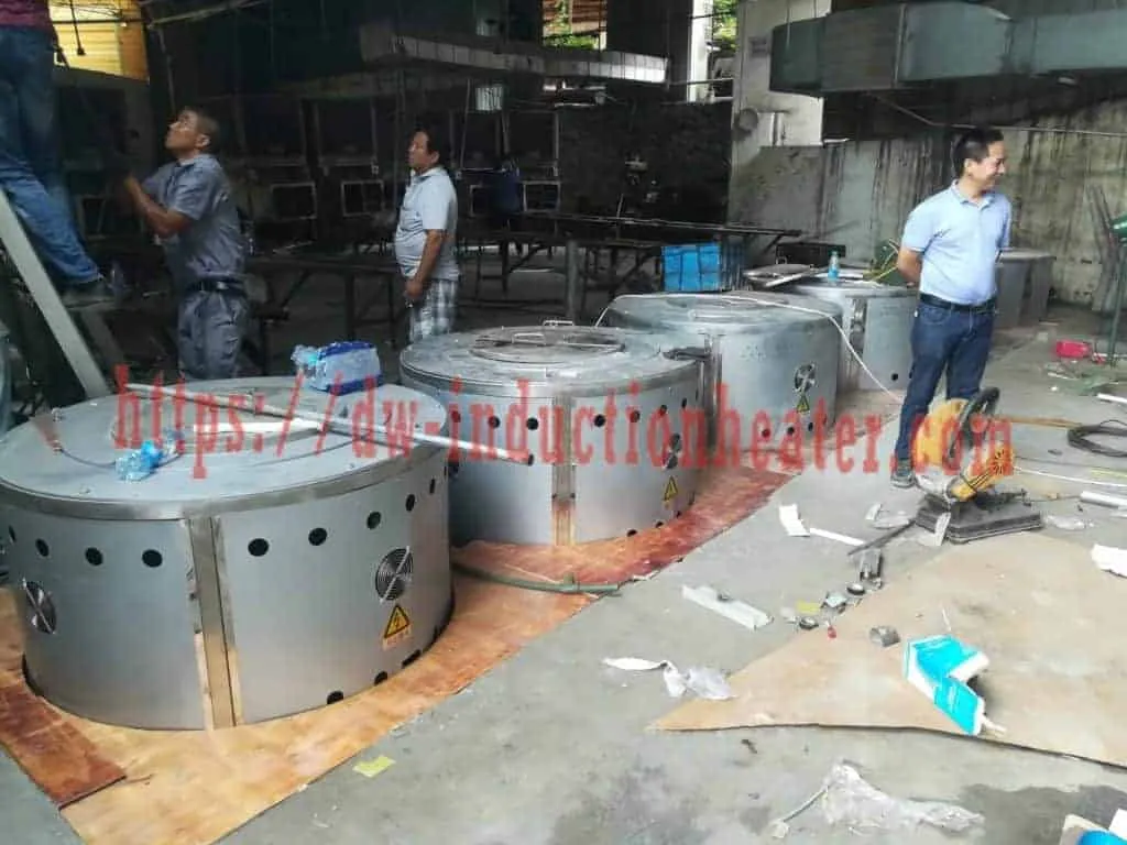
Table of Contents
- Quick Answer
- Table of Contents
- What is the Aluminum Cans Melting Furnace?
- Key Applications
- Suitable Materials
- Working Principle
- Technical Specifications
- Recommended Model Selection
- Process Workflow
- Common Problems and Solutions
- Engineering Selection Guide
- Advantages and Limitations
- Why Choose HLQ?
- 6 Core FAQs
What is the Aluminum Cans Melting Furnace?
An aluminum cans melting furnace with induction heating is a batch melting furnace built around a charge that is not clean metal. The charge is aluminium cans, can sheet, granulate, or the wider secondary aluminium stream that a recycling plant receives, and the machine’s job is to bring that charge to liquid, recover the metal, and hand over a cast ingot. It is not a refiner and it is not an assay: remelting does not remove chemical impurities, and a mixed charge melts to an average composition that has to be corrected in the melt rather than in the feed.
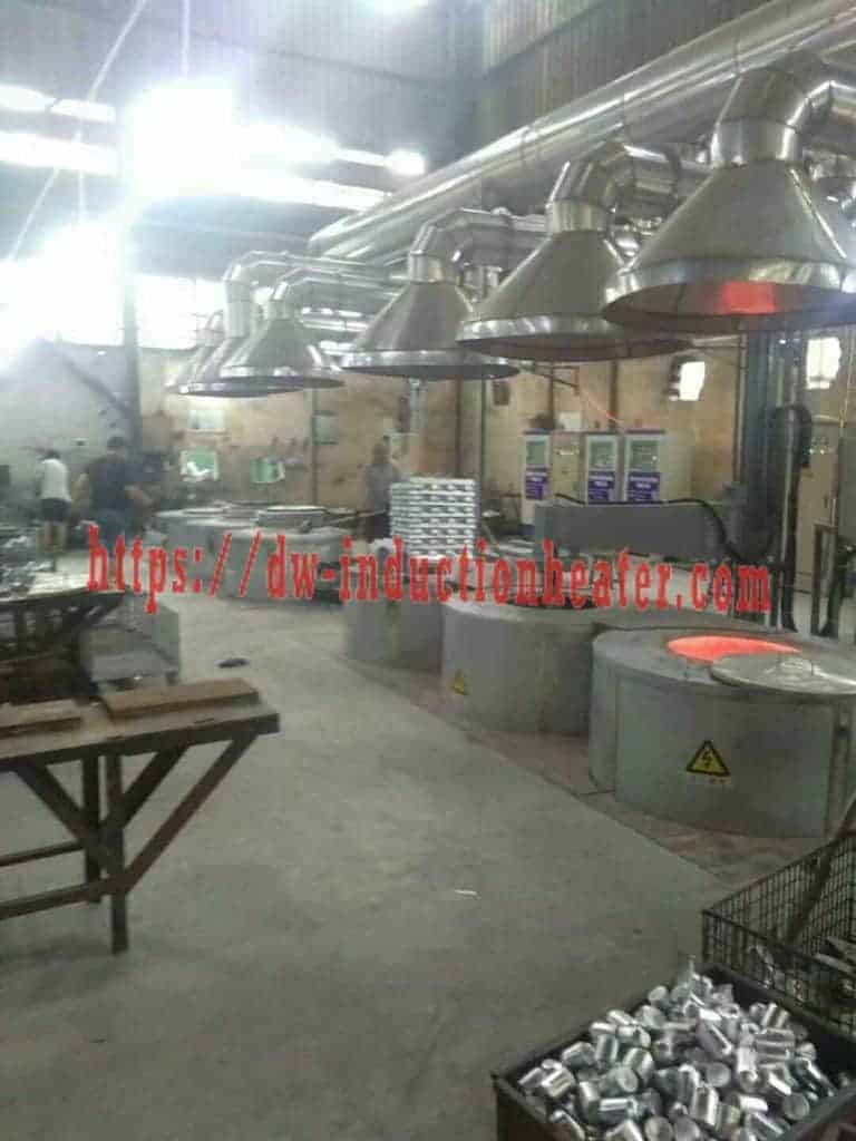
The name matters because it separates this machine from a fuel-fired can furnace. There is no burner, no flue, no stack and no combustion exhaust to route, and the published environmental advantage is that the furnace is electricity-powered with no air pollution, no dust and little noise. On a plant that handles coated, painted and oxidised material, that is a material difference in both the permit and the building.
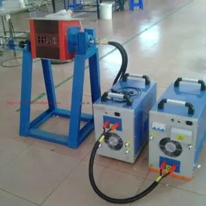
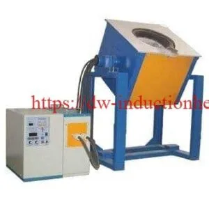
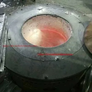
Physically the machine is a steel-shell furnace with an integral refractory lining, a water-cooled copper induction coil, a graphite or SiC-graphite crucible, a tilting mechanism for pouring into ladles or ingot moulds, and a separate medium frequency power supply with its capacitor cabinet. The crucible is the part that does the work: it is the susceptor that the induced current heats, it contains the melt, and it is a consumable with a published drawing. That is why the crucible specification below is not a drawing-office detail but the centre of the furnace specification.
The machine and casting-cycle detail is covered in full on HLQ’s aluminum melting induction furnace page, and the wider secondary-aluminium plant scope sits on the induction melting aluminum reference. This page is written for the buyer specifying a furnace to melt cans: the can-specific behaviour, the frequency decision, the complete published specification, and the questions the published data still leaves open.

Key Applications
HLQ publishes the charge list for this series in the capacity table as aluminum, aluminum alloy, aluminum scrap, aluminum slag and pop can, and publishes a suitability rating for each aluminium feed. That rating is the honest starting point for a can plant, because it says which feeds can be charged straight away and which need preparation first.
| Feed | Published suitability | Published engineering note |
|---|---|---|
| Pure aluminum | Excellent | Easy to melt, good fluidity. |
| Aluminum ingots | Excellent | Stable melting and predictable composition. |
| Al-Si casting alloy | Excellent | Die casting, automotive parts, general casting. |
| Al-Mg alloy | Good | Temperature control and fluxing reduce oxidation and burning loss. |
| Al-Cu alloy | Good | Temperature uniformity and mixing matter. |
| Aluminum alloy scrap | Good | Sort by alloy grade. |
| Aluminum cans | Conditional | Thin and coated; clean, dry and charge carefully. |
| Aluminum chips | Conditional | Dry and compacted; remove oil, water and cutting fluid. |
That table gives the can plant four practical duties.
Melting sorted can scrap into ingots. Once the charge is clean, dry and separated by alloy, a can plant’s furnace is doing exactly what a foundry furnace does, and the published eight-step sequence in the Process Workflow section is the operating document for it.
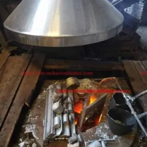
Handling the coating as a separate stream. A can is not just aluminium. The coating, the lacquer and the printing ink do not melt with the metal; they float, they form the dross layer, and they are skimmed off with a steel ladle. On a plant that melts thousands of tonnes, the dross stream is not a rounding error, it is a hot waste stream with its own handling route and its own cost. That is why the published dross station sits between the furnace and the sorting bay in the layout below, and why the dross volume per heat is one of the questions this page asks the supplier to answer.
Recovering aluminium slag. The capacity table lists aluminum slag alongside scrap and pop can, so the furnace treats recovered residue as a feed rather than as waste, and the residue skimmed from the melt goes back through the plant as its own stream.
Handling the alloy mix.** The published note for aluminium alloy scrap is “sort by alloy grade”, and the published suitability for Al-Mg and Al-Cu is good rather than excellent, with temperature control and fluxing named as the measures that reduce oxidation and burning loss. A can plant that mixes alloys at the weighbridge is choosing the dross rate and the ingot specification at the same time.

Suitable Materials
Aluminium is an easy metal to melt and a difficult one to keep clean. Its melting point is published by HLQ at 1220.66 °F, which is 660 °C, the published operating range for this series is 680-760 °C, and the published maximum furnace temperature is 1800 °C. The difficulty is not the heat but the surface: aluminium oxidizes quickly, and every extra minute held above the working range is metal lost as dross rather than saved as electricity.
| Metal | Typical melting or operating temperature | Published lining or crucible recommendation |
|---|---|---|
| Aluminum alloys | Pure Al melts at about 660 °C; usual operating range 680-760 °C | Graphite, SiC-graphite or high-alumina |
| Brass and tin bronze | Approximately 850-1000 °C | Silica or alumina; graphite or SiC crucible |
| Copper | Approximately 1083-1100 °C | Magnesia lining; graphite or SiC crucible on small furnaces |
| Cast iron | Approximately 1150-1400 °C | Acidic, neutral or basic refractory lining |
| Stainless steel | Approximately 1400-1550 °C | Neutral or basic lining |
| Carbon and low-alloy steel | Approximately 1450-1650 °C | Acidic, neutral or basic refractory lining |
| Zinc alloy | Low temperature | Low-temperature-compatible refractory lining |
For an aluminium can plant the published vessel recommendation is graphite, SiC-graphite or high-alumina, and the published furnace lining is an integral structure of polycrystalline mullite fibres rated above 1200 °C. The charge list on this series also covers copper, gold and silver scrap and slag at 500 kg to 3,000 kg per heat, which matters for a plant that handles mixed non-ferrous returns alongside the can stream.
The energy figures explain why aluminium is the cheap metal to remelt, and why a can plant’s cost is dominated by preparation and dross rather than by the melt itself.
| Metal | Heated to | Theoretical heat (rounded) |
|---|---|---|
| Gold | 1100 °C | About 0.06 kWh/kg |
| Copper | 1150 °C | About 0.19 kWh/kg |
| Aluminum | 720 °C | About 0.30 kWh/kg |
| Cast iron | 1450 °C | About 0.38 kWh/kg |
| Steel | 1600 °C | About 0.40 kWh/kg |
Those are ideal heat into the metal only. The real electrical input is higher because the furnace body, the coil and the crucible absorb heat and because a pouring superheat has to be added on top, and the published practical consumption reference for aluminum is 500-780 kWh/T. For a can plant the published energy advantage is 20-40 % power saving against a diesel furnace on the product page and 20-30 % against gas and oil in the manufacturer manual, which are two different baselines and worth asking a supplier which one a quotation is built on. HLQ’s aluminum melting oven reference carries the terminology map and the same energy data for the wider equipment family.

Working Principle
HLQ describes the working principle of this machine in its own manual, and it is worth reading carefully because it explains what the power supply is actually doing for a charge made of thin coated sheet.
“Electromagnetic melting furnaces use electromagnetic induction heating to convert electrical energy into thermal energy through an electromagnetic induction heating controller. First of all, through the internal rectifier filter circuit to AC power into DC, and then through the control circuit to convert DC power into high-frequency magnetic energy. High-speed changing current through the coil will produce a high-speed changing magnetic field. When the magnetic field lines in the magnetic field pass through the crucible, numerous small eddy currents will be generated inside the crucible, so that the crucible itself is heated at a high speed, and the heat will be transferred to the aluminum alloy and melted into a liquid state.”
Read against a can charge, that chain produces four specific effects, and they are the reason this furnace behaves differently on cans than on ingots.
| Step | What happens | Why it matters for can scrap |
|---|---|---|
| Charge enters clean and dry | The published suitability note is: thin and coated, clean, dry and charge carefully. | Moisture is the safety issue and contamination is the yield issue. Neither is a furnace setting. |
| The sheet heats from the surface inward | The induced current flows in a thin skin at the surface of the metal. | Thin sheet reaches melt temperature quickly, which is why can scrap is a fast-melting charge. |
| The coating does not melt with the metal | Residue from the coating and paint floats on the surface and forms the dross layer. | Every can contributes dross. On a can plant this is a continuous hot waste stream, not an occasional skim. |
| The dross is skimmed off | The published procedure skims the residue with a steel ladle, and it has to cool before it can be disposed of safely. | Skimming is a scheduled operation in the published melting sequence, with the dross station as a separate plant area. |
The frequency question follows directly from that second point, because the depth of the heated skin is a function of frequency alone. HLQ publishes these depths, and they are the thickness of metal actually being heated by induction rather than the depth of the bath.
| Frequency | 4 kHz | 10 kHz | 20 kHz | 80 kHz |
|---|---|---|---|---|
| Depth of current penetration | About 4.0 mm | About 2.5 mm | About 1.8 mm | About 0.9 mm |
A deep penetration suits a heavy sorted charge and a deep bath. A shallow one suits very thin material such as a crushed can wall, where a deeper penetration would waste energy heating the interior of a piece that is already thin enough to heat through. The published frequency band for aluminum generally is about 0.5-20 kHz, while gold sits at about 1-80 kHz, and the SMJD series is published from 1 kHz to 100 kHz with a custom frequency available on request. **A can plant running both granulate and heavier sorted scrap sets the frequency for the lighter feed, and that single choice determines how the whole power supply is specified.** The published maximum furnace temperature is 1800 °C, the load duration is 100 % for 24 hours, the power devices are IGBT, and the temperature control is PID with an LED digital controller accurate to 3 °C.

Technical Specifications
The following three tables are the SMJD specification sheet reproduced in full. They are the authoritative source for this equipment and they are published by HLQ in the parameter PDF linked at the top of this page.
1. Melting capacity of the SMJD series
| Type | Input power | Melting capacity: steel and stainless steel | Melting capacity: copper, gold, silver (scrap, slag) | Melting capacity: aluminum, aluminum alloy, aluminum scrap, aluminum slag, pop can | Max temperature |
|---|---|---|---|---|---|
| SMJD-463 | 60 kW | 200 kg | 500 kg | 200 kg | 1800 °C |
| SMJD-480 | 60 kW | 150 kg | 500 kg | 150 kg | 1800 °C |
| SMJD-580 | 80 kW | 200 kg | 600 kg | 200 kg | 1800 °C |
| SMJD-600 | 60 kW | 230 kg | 560 kg | 230 kg | 1800 °C |
| SMJD-900 | 120 kW | 300 kg | 900 kg | 300 kg | 1800 °C |
| SMJD-905 | 80 kW | 300 kg | 900 kg | 300 kg | 1800 °C |
| SMJD-1250 | 80 kW | 400 kg | 1,200 kg | 400 kg | 1800 °C |
| SMJD-1250 | 120 kW | 450 kg | 1,350 kg | 450 kg | 1800 °C |
| SMJD-1500 | 120 kW | 500 kg | 1,500 kg | 500 kg | 1800 °C |
| SMJD-1550 | 120 kW | 520 kg | 1,560 kg | 520 kg | 1800 °C |
| SMJD-1700 | 160 kW | 600 kg | 1,700 kg | 600 kg | 1800 °C |
| SMJD-2300 | 160 kW | 800 kg | 2,000 kg | 800 kg | 1800 °C |
| SMJD-3100 | 200 kW | 1,200 kg | 3,000 kg | 1,200 kg | 1800 °C |
Two things a buyer should notice. The SMJD-1250 appears twice, at 80 kW and at 120 kW, with 400 kg and 450 kg of aluminum respectively, and the crucible specification below lists only one SMJD-1250 crucible for both, so the two ratings share a vessel and differ in power supply. And the aluminum column is identical to the steel and stainless column in every row, which is how the source presents it; the aluminum-specific rating for a can plant is that third column, running 150 kg to 1,200 kg.
2. Main technical parameters
| Type | Output power | Input current | Input voltage | Oscillation frequency |
|---|---|---|---|---|
| SMJD-463 | 60 kW | 90 A | 3-phase 380 V, 50-60 Hz | 1 kHz – 100 kHz, custom frequency according to customer request |
| SMJD-480 | 60 kW | 90 A | 3-phase 380 V, 50-60 Hz | 1 kHz – 100 kHz, custom frequency according to customer request |
| SMJD-580 | 80 kW | 120 A | 3-phase 380 V, 50-60 Hz | 1 kHz – 100 kHz, custom frequency according to customer request |
| SMJD-600 | 60 kW | 90 A | 3-phase 380 V, 50-60 Hz | 1 kHz – 100 kHz, custom frequency according to customer request |
| SMJD-900 | 120 kW | 180 A | 3-phase 380 V, 50-60 Hz | 1 kHz – 100 kHz, custom frequency according to customer request |
| SMJD-905 | 80 kW | 120 A | 3-phase 380 V, 50-60 Hz | 1 kHz – 100 kHz, custom frequency according to customer request |
| SMJD-1250 | 80 kW | 120 A | 3-phase 380 V, 50-60 Hz | 1 kHz – 100 kHz, custom frequency according to customer request |
| SMJD-1250 | 120 kW | 180 A | 3-phase 380 V, 50-60 Hz | 1 kHz – 100 kHz, custom frequency according to customer request |
| SMJD-1500 | 120 kW | 180 A | 3-phase 380 V, 50-60 Hz | 1 kHz – 100 kHz, custom frequency according to customer request |
| SMJD-1550 | 120 kW | 180 A | 3-phase 380 V, 50-60 Hz | 1 kHz – 100 kHz, custom frequency according to customer request |
| SMJD-1700 | 160 kW | 240 A | 3-phase 380 V, 50-60 Hz | 1 kHz – 100 kHz, custom frequency according to customer request |
| SMJD-2300 | 160 kW | 240 A | 3-phase 380 V, 50-60 Hz | 1 kHz – 100 kHz, custom frequency according to customer request |
| SMJD-3100 | 200 kW | 300 A | 3-phase 380 V, 50-60 Hz | 1 kHz – 100 kHz, custom frequency according to customer request |
3. Crucible specification
| Type | Specification | Upper mouth outer diameter (A), ±10 mm | Upper mouth inner diameter (B), ±5 mm | Bottom outer diameter (C), ±10 mm | Total height (H), ±10 mm |
|---|---|---|---|---|---|
| SMJD-463 | 463# | 565 mm | 500 mm | 310 mm | 617 mm |
| SMJD-480 | 480# | 510 mm | 420 mm | 400 mm | 710 mm |
| SMJD-580 | 580# | 420 mm | 360 mm | 300 mm | 840 mm |
| SMJD-600 | 600# | 620 mm | 525 mm | 620 mm | 470 mm |
| SMJD-900 | 900# | 520 mm | 425 mm | 510 mm | 960 mm |
| SMJD-905 | 905# | 620 mm | 530 mm | 620 mm | 650 mm |
| SMJD-1250 | 1250# | 620 mm | 535 mm | 620 mm | 850 mm |
| SMJD-1500 | 1500# | 735 mm | 640 mm | 460 mm | 900 mm |
| SMJD-1550 | 1550# | 775 mm | 682 mm | 400 mm | 750 mm |
| SMJD-1700 | 1700# | 610 mm | 500 mm | 610 mm | 620 mm |
| SMJD-2300 | 2300# | 880 mm | 775 mm | 355 mm | 1000 mm |
| SMJD-3100 | 3100# | 780 mm | 645 mm | 780 mm | 1400 mm |
4. Published features and protection
| Feature | Published specification |
|---|---|
| Power devices | IGBT power devices, high reliability, stable operation and low maintenance costs. |
| Frequency control | Digital phase locked loop tracking frequency, automatic load impedance matching. |
| Power control | Power closed-loop control, to avoid the temperature change caused by the power down. |
| Protection | Over-voltage, under-voltage, phase loss, over-current and over-heat protection; real-time display of the parameters; fault diagnosis and alarm; leakage automatic alarm, cut off the power supply and real-time display of the working state. |
| Heating control | PID heating control system, uniform heating temperature, prevents molten aluminum temperature drift, less burning and more homogeneous metal composition, improving the product qualification rate. |
| Temperature controller | LED digital temperature controller, measuring and controlling accuracy up to 3 °C. |
| Furnace lining | Integral structure of polycrystalline mullite fibres, small volume, good insulation, low energy consumption, high efficiency, temperature above 1200 °C, long service life. |
| Operation | Simple to operate, and the power can be adjusted with the work. |
| Load duration | 100 % load duration, maximum power, ensuring 24 hours of operation. |
| Mould and casting | Precisely engineered moulds for accurate ingot dimensions and consistent quality, with refractory materials that withstand molten aluminum temperatures; automated control of pouring, cooling and ejection; enclosed casting areas, emergency stop systems and proper ventilation; ingots and billets for further processing into sheet, extrusions or castings. |

Recommended Model Selection
Start from the charge that actually arrives at the weighbridge and the heat size the plant has to run, then work to the model. For a can plant the published capacity of each model is the number that sets the size of the heat, and the published crucible dimensions determine what physically fits into the mouth.
| Your charge per heat | Model candidates | Published input power / current | Crucible inner mouth (B) | Crucible height (H) |
|---|---|---|---|---|
| 150 kg | SMJD-480 | 60 kW / 90 A | 420 mm | 710 mm |
| 200 kg | SMJD-463, SMJD-580 | 60 kW / 90 A, 80 kW / 120 A | 500 mm, 360 mm | 617 mm, 840 mm |
| 230 kg | SMJD-600 | 60 kW / 90 A | 525 mm | 470 mm |
| 300 kg | SMJD-900, SMJD-905 | 120 kW / 180 A, 80 kW / 120 A | 425 mm, 530 mm | 960 mm, 650 mm |
| 400 kg | SMJD-1250 (80 kW) | 80 kW / 120 A | 535 mm | 850 mm |
| 450 kg | SMJD-1250 (120 kW) | 120 kW / 180 A | 535 mm | 850 mm |
| 500 kg | SMJD-1500 | 120 kW / 180 A | 640 mm | 900 mm |
| 520 kg | SMJD-1550 | 120 kW / 180 A | 682 mm | 750 mm |
| 600 kg | SMJD-1700 | 160 kW / 240 A | 500 mm | 1200 mm |
| 800 kg | SMJD-2300 | 160 kW / 240 A | 775 mm | 1000 mm |
| 1,200 kg | SMJD-3100 | 200 kW / 300 A | 645 mm | 1400 mm |
Two selections in that table matter more on a can duty than the rest. The SMJD-900 and SMJD-905 both melt 300 kg but at 120 kW and 80 kW with different crucibles, so on a can plant the choice is between a faster melt and a smaller power supply, and the crucible is what decides how much bulk charge the furnace will physically take. And the SMJD-1250 pair shares one crucible, so the 80 kW version is the same vessel at lower power and the 120 kW version is the higher-power one; a plant expecting to grow into the 450 kg figure should specify the 120 kW unit from the start.
For the melt time, HLQ publishes a capacity-to-power-to-time reference that covers the whole induction melting range, and the row a can plant needs is the one matching its batch.
| Capacity | Recommended power | Approximate melting time per batch | Typical application |
|---|---|---|---|
| 50 kg | 30-80 kW | 20-60 min | Lab, small casting |
| 100 kg | 60-120 kW | 30-70 min | Small foundry |
| 250 kg | 120-250 kW | 40-90 min | Medium casting |
| 500 kg | 250-500 kW | 45-100 min | Industrial foundry |
| 1,000 kg | 500-1,000 kW | 60-120 min | Large production |
| 2,000 kg | 1,000-1,600 kW | 90-150 min | Heavy foundry |
| 3,000 kg | 1,500-2,500 kW | 100-180 min | High-capacity melting |
That reference table is plant-level and it implies a higher power density than the SMJD series’ own published figures, which is worth resolving before the transformer is specified. On the wider plant scope, HLQ’s aluminum smelter with induction heating page covers the secondary production line, the feedstock routes and the plant utilities, and the industry melting aluminum furnace page carries the electrical sizing check for an industrial installation.


Process Workflow
A can plant is judged on the whole route rather than on the melt, and the published operating sequence is an eight-step cycle in which every step carries a stated control point.
| Step | Operation | Key control point |
|---|---|---|
| 1 | Prepare the charge: clean, dry and sorted by alloy | No water, oil or sealed cavities |
| 2 | Check the furnace: lining, cooling water and alarms | Water flow and pressure |
| 3 | Charge the crucible; add more charge as it melts | Correct charge order |
| 4 | Melt at full power with electromagnetic stirring | Power and time |
| 5 | Check temperature and chemistry | Immersion probe or pyrometer |
| 6 | Skim slag or dross; add flux if required | Melt cleanliness |
| 7 | Tilt and pour into a ladle or moulds | Pouring temperature |
| 8 | Re-charge or hold; inspect the lining after each shift | Lining wear |
Steps 1 and 6 are where the can duty differs from a foundry duty. Step 1 is the sorting, granulation and drying line, and on cans it decides the yield, because the published suitability note is that the charge must be clean, dry and charged carefully. Step 6 is where the metal is actually recovered: the published procedure skims the residue with a steel ladle, and the dross is a separate hot stream that has to cool before it can be handled safely. Step 8 is the shift-end lining inspection, and on aluminium the lining wears fastest where the dross line sits.
Step 3, “correct charge order”, deserves a sentence for a plant running mixed feed. The published control point for charging is the order of the charge, not simply its weight. Ordering the charge so that the melt sees a consistent composition through the heat is what makes the temperature measurement at step 5 meaningful and the alloy correction at step 6 possible.
| Published item | Value | Published item | Value |
|---|---|---|---|
| Aluminum capacity per heat | 150 kg – 1,200 kg | Input power | 60 kW – 200 kW |
| Input current | 90 A – 300 A | Supply | 3-phase 380 V, 50-60 Hz |
| Oscillation frequency | 1 kHz – 100 kHz | Max furnace temperature | 1800 °C |
| Aluminum melting point | 1220.66 °F (660 °C) | Operating range | 680 – 760 °C |
| Load duration | 100 %, 24 hours | Power devices | IGBT |
| Temperature control | PID, LED controller to 3 °C | Lining | Mullite fibre, above 1200 °C |


Common Problems and Solutions
The published troubleshooting reference for induction melting covers the failures a can plant actually meets, and the aluminum-specific rows matter most here because aluminium behaves differently from steel and copper in exactly the ways a plant operator has to manage.
| Problem | Likely cause | Published solution |
|---|---|---|
| Violent eruption when charging | Wet, oily or sealed scrap | Charge only clean, dry material and remove sealed cavities |
| Melting slower than expected | Power too low for the batch, or poor charge packing | Check power against the capacity table and improve charge density; on the SMJD series the PID heating control and closed-loop power control hold the set point |
| Short lining life | Wrong lining chemistry for the metal or the slag | Choose an acidic, neutral or basic lining to suit the metal; the SMJD furnace is published with an integral polycrystalline mullite fibre lining rated above 1200 °C |
| Dross and burning loss with aluminum | Thin, dirty or coated scrap; high temperature | Clean and dry the charge, control the temperature and use flux; the published procedure skims the residue with a steel ladle |
| Zinc loss and fume with brass | Overheating and zinc fuming | Control the temperature and use fume extraction |
| Water alarm or trip | Low flow or pressure, or blocked circuits | Check the cooling tower or chiller, the water quality and the filters; the SMJD protection package includes over-heat and leakage alarms with automatic power cut-off |
| Alloy composition uneven across the melt | Charge not stirred, or charge order wrong | Electromagnetic stirring mixes the alloy and evens out the temperature; the control point for the melt step is power and time, and for the charge it is charge order |
| Temperature drift across the melt | Load changes as the charge melts and more metal is added | PID heating control for uniform heating temperature and prevention of molten aluminum temperature drift, with an LED digital controller of up to 3 °C accuracy |
| Power fluctuation as the load changes | Impedance changes from a cold solid charge to a full bath | Digital phase-locked-loop frequency tracking with automatic load impedance matching, plus closed-loop power control |
The first row and the dross row are the two that decide whether a can plant is viable. A charge that arrives wet or oily is a safety incident waiting to happen at the crucible, and the published protection set cannot substitute for a dry charge. Dross and burning loss are the economic half of the same problem, and on a coated feed the published answer is threefold: clean and dry the charge, control the temperature, and use flux.
Engineering Selection Guide
Selecting an aluminum can melting furnace has four parts, and the one that catches buyers is the last, because the published specification does not cover it.
Part one: the furnace.** The published selection factors are the checklist for it, and each one is a decision made before the equipment is ordered rather than after it is installed.
| Selection factor | What to confirm | Published recommendation |
|---|---|---|
| Metal type | Aluminum, copper, iron, steel, gold or another alloy | Select lining chemistry and power density by metal |
| Batch capacity | Kilograms or tons per melt | Allow a practical loading and pouring margin |
| Target melting time | Minutes per batch | Higher power shortens melting but needs a larger supply |
| Daily production | Tons per shift or per day | Decide on one furnace, several furnaces or a dual-output power supply |
| Power supply | Plant voltage, transformer capacity, cable size | Confirm electrical capacity before ordering |
| Tilting | Manual, mechanical or hydraulic | Hydraulic for medium and large furnaces |
| Cooling | Water flow, pressure, temperature and quality | Closed-loop cooling tower or industrial chiller |
| Layout | Charging area, crane, ladle path, mould area | Plan the layout before fixing the furnace dimensions |
| Continuous casting | Rod, bar, strip or wire output | See the small induction melting and continuous casting furnace |
Part two: the plant envelope and the utilities. The published ranges below are where the furnace sits in the plant, and cooling is the utility that stops production when it fails.
| Parameter | Published range | Notes |
|---|---|---|
| Batch capacity | 0.5 kg (gold) to 5,000 kg | Customised to batch weight and daily output |
| Power | 3 kW (small gold melters) to 3,500 kW (large copper furnaces) | Set by batch weight and target melting time |
| Frequency | Gold about 1-80 kHz; aluminum about 0.5-20 kHz; copper about 0.25-8 kHz; iron and steel about 0.5-2.5 kHz | Lower frequency is used for larger furnaces |
| Input voltage | 380 V, 660 V, 750 V, 1,000 V or customised | Depends on power level and plant supply |
| Furnace body | Steel shell or aluminum shell | Steel shell for larger, heavy-duty furnaces |
| Tilting | Hydraulic, gearbox or manual; fixed design possible | Hydraulic tilting recommended for medium and large furnaces |
| Cooling | Closed-loop cooling tower or industrial chiller | For coil, power supply, capacitors and cables |
| Temperature measurement | Thermocouple, immersion probe or infrared pyrometer | Immersion measurement is common for molten metal |
| Control | Manual, digital, PLC or HMI | Automation improves repeatability |
| Protection | Over-current, over-voltage, water pressure, phase loss; leak alarm optional | Full protection recommended for large iron and steel furnaces |
On cooling specifically, HLQ’s published statement is that the induction coil, the water-cooled cables, the capacitor cabinet and the power supply all generate heat during operation, and that insufficient cooling causes alarms, insulation damage, coil failure or safety hazards. On a can plant running multi-shift, the cooling system is a production-critical asset rather than a service item, and these are its published checkpoints.
| Safety / cooling item | Function | Published recommendation |
|---|---|---|
| Cooling water system | Cools coil, power supply, capacitors and cables. | Use stable water flow, correct pressure and good water quality. |
| Water pressure protection | Stops system under insufficient water pressure. | Required for safe continuous operation. |
| Leak furnace alarm | Detects furnace lining failure or molten metal leakage risk. | Recommended for steel, iron and large furnace systems. |
| Over-current protection | Protects power components under abnormal load. | Important during charging and melting stage. |
| Over-voltage protection | Prevents electrical damage during unstable conditions. | Improves power supply reliability. |
| Phase-loss protection | Protects the system from missing phase input. | Reduces damage caused by poor electrical supply. |
| Hydraulic tilting safety | Controls molten metal pouring movement. | Check hydraulic cylinder, limit switch and emergency stop regularly. |
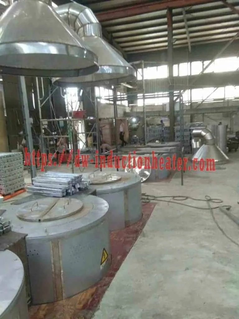
Part three: the site. The layout below is what a can melting shop has to accommodate, and the dross loop is the part most often missing from the plan.

Part four: the questions the published specification does not answer. The table below is a gap analysis of HLQ’s published material for this series, checked against the three official PDFs and the product page. For a can plant these are not details; they are the questions that decide whether the furnace can run the feed the plant actually receives. **None of them is answered by the published specification, and all of them should be settled with HLQ before the order is placed.**
| Question a can plant still has to ask | Why it matters | What to request |
|---|---|---|
| Can-wall coating and lacquer | Residue does not melt with the metal; it floats and forms the dross layer. | Coating types accepted, flux practice, expected dross rate |
| Steel end rings and bimetal cans | A steel fraction in the charge changes the melt chemistry and adds to the dross. | A stated steel limit and how bimetal cans are handled |
| Charge form: whole can, granulate or sheet | The published note covers cans as one item; the form changes charge density. | Which forms the furnace is rated for, and the bulk density |
| Moisture and residual liquid limit | The published note says dry and charge carefully, but publishes no moisture figure. | A charge moisture limit and the check used on the weighbridge |
| Dross chemistry and disposal route | Dross is a separate hot stream and the specification does not describe its composition. | Expected dross volume per heat and the safe handling route |
| Crucible fill limit for a bulk charge | The published dimensions describe the vessel, not how far a can charge is filled. | The permissible fill limit and the dross headroom for the feed |
HLQ’s published layout reference runs from a 10-100 kg laboratory crucible through 150-350 kg, 500-1,000 kg, 1,500-3,000 kg and up to 3,000-5,000 kg heavy industrial melting, and its published plant safety practice is an enclosed casting area with emergency stop systems and proper ventilation, plus fume capture wherever a zinc-bearing alloy is melted. For the wider plant scope and the electrical sizing check on an industrial installation, HLQ’s industry melting aluminum furnace page carries the transformer, cable and power-density analysis.

Advantages and Limitations
Advantages
| Advantage | Engineering meaning | Buyer value |
|---|---|---|
| No fuel and no combustion | Electricity-powered: no air pollution, no dust and little noise. | No flue to route and no burner to maintain, and no combustion exhaust in the permit conditions. |
| Energy saving against fuel-fired melting | Published 20-40 % power saving against a diesel furnace on the product page, and 20-30 % against gas and oil in the manual. | A lower running cost per tonne, but the figure depends on which baseline the quotation uses. |
| Rapid, accurately controlled heating | Induction heating is fast and the temperature control is real-time and accurate. | Thin can sheet reaches melt temperature quickly, which suits a high-throughput can stream. |
| Long service life, simple maintenance | The electromagnetic heating coil is insulated and high temperature, with no element to oxidize and burn out. | Removes the element-replacement cycle that resistive furnaces impose on a 24-hour plant. |
| Lower surface temperature | Induction heating reduces the surface temperature of the machine exterior. | Less burn and scald risk around the furnace. The pour itself remains hazardous. |
| Electromagnetic stirring | The field mixes the melt, so temperature and composition stay even. | Fewer off-specification ingots when the feed is a mixed can stream. |
| Continuous industrial duty | Published 100 % load duration for 24 hours at maximum power. | Matches a multi-shift recycling plant. |
| Automatic load matching | Digital phase locked loop tracking with automatic load impedance matching plus closed-loop power control. | Keeps a mixed, coated charge melting on plan without constant operator adjustment. |
| Documented, repeatable production | Eight-step published sequence with a control point on every step, plus a batch log. | Lets the plant hold the same ingot specification across shifts and operators. |
Limitations
| Limitation | Consequence | Recommended approach |
|---|---|---|
| The published capacity is feed-specific | Cans are published as conditional: thin and coated, clean, dry and charge carefully. A charge that does not meet that condition will not melt to the published rate. | Build sorting, granulation, drying and de-oiling into the plant, and rate the furnace on the feed actually received. |
| Dross is a continuous hot stream | Every can contributes residue that does not melt with the metal, and the published procedure skims it with a steel ladle for cooling before handling. | Plan the dross station, the cooling route and the flux practice before the furnace is ordered, and ask HLQ for the expected dross volume per heat. |
| Cooling water is not optional | The coil, water-cooled cables, capacitor cabinet and power supply all generate heat; insufficient cooling causes alarms, insulation damage, coil failure or safety hazards. | Use a closed-loop cooling tower or industrial chiller with flow and pressure protection, and treat it as production-critical. |
| The plant needs a dedicated electrical supply | Melting at this scale needs a large three-phase installation, a transformer sized for the sum of the furnace currents, and a busbar and cable sized on the real power factor. | Confirm transformer capacity, input voltage, breaker rating and cable size before installation. |
| Refractory lining and crucible are consumables | The lining is exposed to high temperature, slag attack and mechanical damage and wears fastest at the dross line; the crucible is also the susceptor. | Select the lining chemistry to suit the metal and slag, inspect after each shift as the published sequence requires, and hold a spare crucible and coil for each model. |
| A remelter is not a refiner | Remelting does not remove chemical impurities or change the alloy composition of a mixed feed. | Sort by alloy grade, correct the chemistry in the melt, and use separate refining and assay processes where certified purity is required. |
| Molten-metal hazards remain | Burn, splash, fume and moisture-contact risks are not removed by induction heating. | Use a controlled workspace, PPE, extraction and trained operators. |

Why Choose HLQ?
HLQ Induction Equipment has been developing and producing high frequency and medium frequency induction heating and melting equipment for 25 years, and the published SMJD material is unusually complete for an industrial buyer: three specification tables including the crucible drawing, a manufacturer manual with the heating principle, the packing method, the storage conditions and the warranty, and a test-running commitment before shipment.
| Published item | Detail |
|---|---|
| Warranty | 12 months from the contract signed date. |
| Test machine running | HLQ’s technical staff test the machine running before shipment; all machines are tested and debugged carefully before shipment. |
| Quality control | Professional QC personnel inspect machinery during production; the QC team complies with TQM, with each step in compliance to the standards. Photos and video can be provided on request. |
| Delivery | If the buyer has shippers in China the machine can be sent to them free of charge; otherwise it can be sent directly to any main port of China promptly. |
| Packaging | Wrapped with a film layer for waterproof, packed in a paper box, then put into a wooden case (standard exporting carton) and wrapped with foam around for shockproof. |
| Storage conditions | Clean, dry environment; temperature -20 to 60 °C; humidity 0-95 % with no dew; avoid corrosive gases and liquids. |
| After-sales service | Engineers are sent to the customer’s workshop, with installation, debugging and training until the machine is in normal production. |
| Published services | Immediate reply to your inquiry; detailed product and company information; best quotation; immediate reply to your questions; technical support or alternative accessories if necessary. |
| Product range | IGBT medium frequency induction heating equipment, IGBT super audio induction heating equipment, CNC quenching machine tool, IGBT medium frequency induction melting furnace, KGPS medium frequency induction melting furnace, open type water cooling tower and closed water cooling tower. |
For a can plant the three items in that list that matter most are the test-running commitment, because a furnace that has not been run on a representative can charge before shipment is a furnace whose melt time and dross rate are still theoretical; the engineer commissioning, because the published eight-step sequence is only reproducible if somebody sets the recipe; and the twelve-month warranty, which is the only published commitment on the equipment itself.
The neighbouring HLQ pages cover the same product family for other duties, including the metals melting furnace with induction for the small crucible range, the portable gold melting furnace, the stationary gold melting furnace, the tilting gold melting furnace and the melting copper furnace with induction for the non-ferrous side of the same plant.
6 Core FAQs
1. What is an aluminum cans melting furnace with induction heating?
It is a medium frequency electric batch melting furnace that melts aluminium can scrap into a cast ingot, with the heat generated inside the metal rather than in a flame. The SMJD series covers thirteen sizes from SMJD-463 to SMJD-3100, melting 150 kg to 1,200 kg of aluminum per heat from 60 kW to 200 kW input, with published input current 90 A to 300 A, a 3-phase 380 V 50-60 Hz supply, oscillation frequency from 1 kHz to 100 kHz with a custom frequency on request, a maximum furnace temperature of 1800 °C, an integral polycrystalline mullite fibre lining rated above 1200 °C, PID heating control with an LED digital controller accurate to 3 °C, IGBT power devices, and a published 100 % load duration for 24 hours. It is worth being clear about what it is not: the manufacturer’s manual answers the power supply question with a single word, “Electricity”, and the furnace is not a refiner and not an assay.
2. Why are aluminium cans rated only “conditional” while ingots are “excellent”?
Because a can is the one aluminium feed that arrives with something else attached. The published engineering note for cans is “thin and coated; clean, dry and charge carefully”, and for chips “dry and compacted; remove oil, water and cutting fluid”, while pure aluminium and aluminium ingots are published as excellent. The coating, the lacquer and the printing ink do not melt with the metal; they float on the surface and form the dross layer, and the published procedure skims that residue off with a steel ladle. On a can plant this is not a rounding error, it is a continuous hot waste stream with its own handling route and its own cost, which is why the dross station is a separate plant area and why the expected dross volume per heat is one of the questions to put to the supplier.
3. How long does it take to melt a batch of cans?
Published figures are given as a range against batch size rather than per model: 50 kg at 30-80 kW in about 20-60 minutes, 100 kg at 60-120 kW in 30-70 minutes, 250 kg at 120-250 kW in 40-90 minutes, 500 kg at 250-500 kW in 45-100 minutes, and 1,000 kg at 500-1,000 kW in 60-120 minutes. The published SMJD series covers 150 kg to 1,200 kg per heat, and its own published model figures sit at lower power density than that reference implies, so the melt time for a specific model and a specific can charge should be agreed in writing rather than read off a table. A published test criterion to write into the order is 1,000 kg of a specified alloy from ambient to pour-ready in a stated number of minutes.
4. Does the can scrap change the frequency the furnace runs at?
It should, and this is the point most often missed when a can plant quotes a furnace. The depth to which the induced current flows is set by frequency alone, and the published penetrations are about 4.0 mm at 4 kHz, 2.5 mm at 10 kHz, 1.8 mm at 20 kHz and 0.9 mm at 80 kHz. A deep penetration suits a heavy sorted charge and a deep bath; a shallow one suits very thin material such as a crushed can wall, where a deeper penetration would waste energy heating the interior of a piece that is already thin enough to heat through. The published frequency band for aluminum is about 0.5-20 kHz, and the SMJD series is published from 1 kHz to 100 kHz with a custom frequency on request, so a plant running both granulate and heavier sorted scrap sets the frequency for the lighter feed.
5. How much power and electrical capacity does the plant need?
The published SMJD input power is 60 kW to 200 kW and the published input current is 90 A to 300 A per furnace on a 3-phase 380 V supply, so a multi-furnace plant needs the transformer sized for the sum of the currents rather than for one unit, and the published selection guidance is to decide between one furnace, several furnaces, or a dual-output power supply serving two furnace bodies alternately. The published capacity-to-power reference implies 250-500 kW for a 500 kg batch and 500-1,000 kW for a 1,000 kg batch, which is higher than the SMJD series’ own published power density, so the power match should be confirmed for the actual feed before the transformer is specified.
6. What should I confirm with the supplier before ordering?
Nine items. The real aluminum batch weight per heat and the target melt time. The daily tonnage and number of heats per shift, which decides one furnace, several furnaces or a dual-output supply. The feed mix and how much sorting, granulation, drying and de-oiling it needs. The transformer capacity for the published input current, sized on the real power factor rather than the published figure. The oscillation frequency for the lightest feed in the mix. The crucible fill limit for a bulk can charge, since the published crucible dimensions describe the vessel and not how far a charge should be filled. The cooling water specification with flow and pressure protection, treated as production-critical. The expected dross volume per heat and the disposal route for it. And the acceptance criterion in writing, for example 1,000 kg of a specified alloy from ambient to pour-ready in a stated number of minutes, backed by a representative melt-test record before shipment.