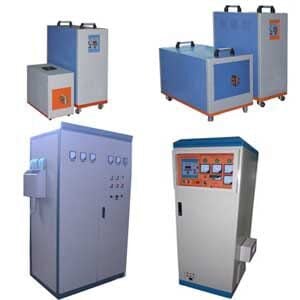
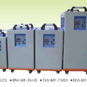
Medium frequency supplies for induction heating
DW-MF-70KW Medium Frequency Induction Heating Power Supply
Quick Answer
The HLQ DW-MF-70KW is a medium frequency induction heating power supply with a published maximum oscillation rating of 70 kW and a 1–20 kHz operating range. Its page lists three-phase 380 V ±10%, 50/60 Hz input, 105 A maximum input current, a separate generator and transformer, and a water-cooling requirement. The 70 kW rating does not by itself establish useful heat delivered to a particular workpiece, its heating time, or its production rate.

Table of Contents
- What is the DW-MF-70KW Medium Frequency Induction Heating Power Supply?
- Key Applications
- Suitable Materials
- Working Principle
- Technical Specifications
- Recommended Model Selection
- Process Workflow
- Common Problems and Solutions
- Engineering Selection Guide
- Advantages and Limitations
- Why Choose HLQ?
- 6 Core FAQs
What is the DW-MF-70KW Medium Frequency Induction Heating Power Supply?
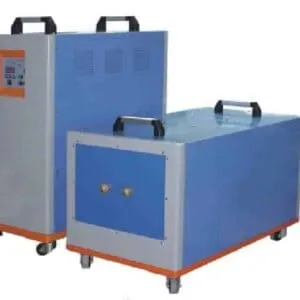
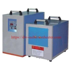
The DW-MF-70KW is the specific model documented on this page in HLQ’s medium frequency heating machine category. The product description identifies an IGBT parallel inverter, while the listed equipment includes a generator, transformer, and induction coils. These components form part of a heating setup whose coil geometry and workpiece process must be matched to the intended application.

The page describes a power supply and its listed components. It does not publish a measured heating cycle or a complete specification for every forging, melting, fitting, or heat-treatment installation named in the application list.
Key Applications
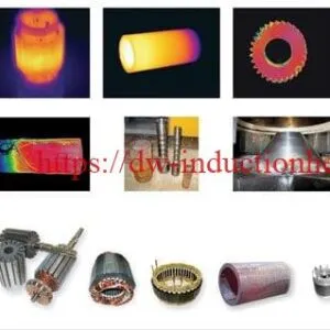
The source page names rod heating before forging, rod-end heating, metal melting, stator or rotor heating for fitting, tube-end heating before extrusion, mold heating, shaft and gear heat treatment, and weld-joint preheating. These are application categories; actual suitability requires a compatible coil, load matching, cooling, and a defined process. HLQ also lists related induction forging equipment and a separate forging and melting induction generator product.
| Application | Heating objective | Information needed for a real process |
|---|---|---|
| Rod or rod-end forging preparation | Heat the required rod region before forming | Material, diameter, heated length, target condition, and cycle time |
| Stator or rotor fitting | Heat a component before assembly | Component geometry and required fitting temperature |
| Tube-end extrusion | Heat the selected tube end | Tube dimensions and coil arrangement |
| Metal melting | Power a compatible induction melting arrangement | Furnace, crucible, coil, charge, and melting cycle |
| Shaft, gear, mold, or weld-joint heating | Apply a defined local or wider heating pattern | Material, treatment objective, temperature measurement, and subsequent process |

The following graphic is an application illustration, not a documented customer case or a guarantee that one coil serves every process.

Suitable Materials
Induction heating requires an electrically conductive workpiece or a suitable conductive part of the heating arrangement. The source page names rods, tubes, stators, rotors, molds, shafts, gears, and metal-melting work, but it does not give an approved material-and-size chart for the DW-MF-70KW. Its broad melting statement should therefore be treated as an application topic, not as a confirmed capacity for every metal. See HLQ’s induction melting applications for the separate furnace context.
| Named workpiece or process | What the page establishes | What it does not establish |
|---|---|---|
| Rods and rod ends | Listed for forging-related heating | Approved rod diameter, alloy, temperature, or heating time |
| Tube ends | Listed for extrusion-related heating | Approved wall thickness or heated length |
| Stators and rotors | Listed for fitting | Approved component geometry or assembly temperature |
| Metal charge for melting | Melting is listed as an application | Furnace capacity, melt rate, or complete furnace specification |
Working Principle
The page describes an IGBT inverter circuit and a medium-frequency induction heating supply. In a matched induction system, alternating current in a coil creates a changing magnetic field that induces heating in a conductive workpiece. The published 1–20 kHz range is a supply specification; the selected operating point depends on the connected load and coil. HLQ’s basic induction heating principle page explains the underlying process.

The power-path diagram below is conceptual. The original page does not publish a detailed circuit schematic or a verified component-by-component loss balance.

Technical Specifications
The values below reproduce the DW-MF-70KW technical table. Terms such as “maximum oscillation power” and “maximum input current” are retained as published; they should not be substituted for measured useful heating power.
| Parameter | Published value | Reading note |
|---|---|---|
| Model | DW-MF-70KW | Only fully specified model on this page |
| Electrical input | Three-phase 380 V ±10%, 50/60 Hz | Source calls this “Input power desire” |
| Maximum oscillation power | 70 kW | Not a measured workpiece heating result |
| Maximum input current | 105 A | Measurement conditions are not given |
| Oscillation frequency | 1–20 kHz | Published range, not one fixed operating point |
| Cooling water | >0.2 MPa; 6 L/min | Flow allocation among components is not specified |
| Duty-cycle statement | 100% at 40°C | Published condition; no independent test record is attached |
| Generator dimensions | 560 × 270 × 470 mm | Component dimensions, not installation clearances |
| Transformer dimensions | 550 × 300 × 420 mm | Component dimensions, not installation clearances |
| Net-weight entry | 45 kg / 55 kg | The page does not explicitly map each value to a component |
| Connecting-cable length | 2–6 m | Published range; exact supplied length is not identified |
The page additionally lists over-voltage, over-current, over-heat, phase-loss, and water-shortage alarm or protection functions. It does not publish their threshold settings or a test report. The original page embeds the HLQ Brochure PDF as a related document.
| Item | Page-listed quantity |
|---|---|
| DW-MF-70KW generator | 1 piece |
| DW-MF-70KW transformer | 1 piece |
| Foot switch | 1 piece |
| Induction coils | 2 sets |
| Coil connecting poles | 2 sets |
| Instruction manual | 1 |
| Packing list and receipt | 1 |
| Guarantee card | 1 |
| Product certificate | 1 |
Recommended Model Selection
The DW-MF-70KW should be selected from a defined workpiece, heating objective, cycle time, coil, and available services. HLQ’s related product list includes an MF-45 medium frequency generator and a separate MF-160 induction generator. Their published maximum oscillation ratings provide power-class references, not interchangeable heating capacities.
| Product page | Published maximum oscillation power | Published frequency | Selection note |
|---|---|---|---|
| MF-45 | 45 kW | 1–20 kHz | Separate model; assess against its own technical page. |
| DW-MF-70KW | 70 kW | 1–20 kHz | Model documented on this page. |
| DW-MF-160KW | 160 kW | 1–20 kHz | Separate model; confirm its own installation requirements. |
The listed two coil sets do not define the coil dimensions or make them suitable for every workpiece. Coil design remains part of selection; see HLQ’s induction heating coils category.
Process Workflow
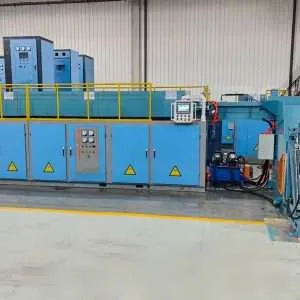
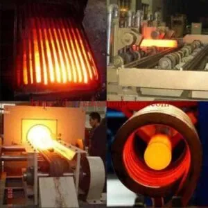
For an illustrative rod-end forging application, define the metal rod and heated zone, match the coil and load, verify power and cooling, establish the heating cycle, and then transfer the heated rod to the separately specified forming operation. HLQ’s related induction bar heating systems page addresses a broader system scope. The DW-MF-70KW page does not publish a measured rod-heating case.
- Record the workpiece material, dimensions, and required heating zone.
- Match the induction coil and electrical load to the workpiece.
- Check the stated electrical and cooling requirements.
- Define the heating power, time, and temperature-assessment method.
- Run the validated heating cycle and assess the result.
- Transfer the workpiece to its separately defined process.
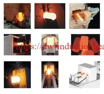
The page also names shaft and gear treatment. Those processes require their own heating and subsequent treatment definition; see HLQ’s induction hardening applications category.

Common Problems and Solutions
The following table is an engineering review aid, not a fault-code list for an installed unit. Operating instructions should follow the documentation for the supplied configuration.
| Concern | Published information | First engineering check |
|---|---|---|
| The workpiece heats differently from the expected pattern | Frequency range is 1–20 kHz; coil dimensions are not published. | Review coil geometry, position, workpiece dimensions, and load matching. |
| Heating rate cannot be predicted from 70 kW | 70 kW is stated as maximum oscillation power. | Measure the actual cycle and define useful workpiece energy separately. |
| Cooling demand is unclear | The table states >0.2 MPa and 6 L/min. | Confirm flow allocation and total cooling needs for the delivered system. |
| Continuous-duty expectation is uncertain | The page states 100% duty cycle at 40°C. | Check the actual ambient, load, cooling, and operating conditions. |
Engineering Selection Guide
The original page provides component dimensions and a cable-length range, but no dimensioned installation layout. The layout image below therefore shows functional relationships only. Selection also requires the actual workpiece, target temperature, time, coil, and cooling circuit.
| Design topic | Published DW-MF-70KW data | Project input still needed |
|---|---|---|
| Electrical supply | Three-phase 380 V ±10%, 50/60 Hz; 105 A maximum input current | Confirmed supply and rating measurement conditions |
| Heating output | 70 kW maximum oscillation rating | Actual power at the coil and useful heat in the workpiece |
| Frequency | 1–20 kHz | Matched operating point for the coil and load |
| Cooling | >0.2 MPa; 6 L/min as written | Full cooling-circuit design and flow allocation |
| Equipment envelope | Generator 560 × 270 × 470 mm; transformer 550 × 300 × 420 mm | Mounting, access, and installation clearances |
| Connection | 2–6 m cable-length range | Exact supplied length and approved routing |
As an arithmetic reference only, balanced three-phase apparent power is S = √3 × line voltage × line current. If the published 380 V and 105 A values occurred together, S would be about 69.1 kVA. The page does not identify the simultaneous test condition, power factor, or the measurement point for “70 kW maximum oscillation power”; this calculation cannot establish efficiency or continuous heating output.

Advantages and Limitations
| Published advantage or useful detail | Limit of the available evidence |
|---|---|
| Defined 70 kW maximum oscillation rating and 1–20 kHz range | No measured useful workpiece heating power or cycle time |
| Generator, transformer, coil, and control-related items are listed | No detailed circuit drawing or coil dimensions |
| Input, cooling, envelope, and cable data are provided | Installation clearances and full cooling allocation are not supplied |
| Multiple applications are named | No single setup is verified for every listed application |
Weld-joint heating appears among the page’s applications. HLQ’s induction preheating applications provide further context, while the required process parameters remain application-specific.
Why Choose HLQ?
HLQ publishes a defined DW-MF-70KW specification table, component dimensions, a page-listed item table, and related medium-frequency products that support an initial equipment comparison. Its related full solid-state induction heater is a separate product rather than another specification for this unit. The available data provide a starting point for matching the supply to a workpiece, coil, electrical source, and cooling system.
6 Core FAQs
1. Which model is specified on this product page?
The detailed technical table is for DW-MF-70KW. Other medium-frequency models appear as related products on separate pages.
2. Does 70 kW mean that 70 kW of heat reaches the workpiece?
No. The page calls 70 kW its maximum oscillation power. It does not provide a measured useful heating-power value for a particular coil and workpiece.
3. What electrical input does the page list?
Three-phase 380 V ±10% at 50/60 Hz, with a published maximum input current of 105 A.
4. What cooling requirement is published?
The table states water pressure above 0.2 MPa and a flow figure of 6 L/min. It does not specify how that flow is allocated among connected components.
5. Are the generator, transformer, and coils listed on the page?
Yes. The page lists one generator, one transformer, two coil sets, and other items in its equipment table. Exact coil dimensions are not published there.
6. Can this power supply alone define metal-melting capacity?
No. Metal melting is named as an application, but melting capacity requires a compatible furnace, coil, crucible or lining, charge definition, cooling system, and verified operating cycle.
Related products
-

Induction Billet Heating System for Forging-Extrusion and Rolling
-
Steel, Titanium,Brass Induction Billet Forging Heater For Extrusion Aluminium, Copper Billet Bar Dies Rod
-
magnetic induction heating system
-
DW-HF-120kw Induction Heating Equipment
-
Titanium Steel Copper Aluminum Billet Forging Heater Induction Billet Heating System