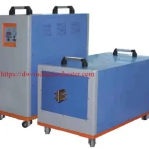
Induction Billet Heating System for Forging-Extrusion and Rolling
Induction Billet Heating System for Steel,Copper,Aluminum Forging-Extrusion and Rolling
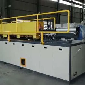
The Induction Billet Heating System is a high-efficiency, solid-state electromagnetic heating solution designed for the rapid, uniform through-heating of metal billets and bars prior to forging, rolling, extrusion, and other hot-forming operations. It processes steel, aluminum, copper, titanium, and alloy billets across a wide range of diameters and lengths, delivering precise, repeatable temperature profiles with minimal scale formation and zero combustion emissions. For manufacturers replacing gas furnaces or resistance furnaces, it solves the core problems of slow heating cycles, high energy waste, inconsistent temperature uniformity, excessive surface oxidation, and the inability to integrate with automated production lines and Industry 4.0 data systems.
Quick Answer
The Induction Billet Heating System is a medium-to-low frequency (0.5–10 kHz), IGBT-driven solid-state induction power supply paired with a multi-turn solenoid heating coil and an automated billet feed mechanism, purpose-built for through-heating metal billets to forging, extrusion, or rolling temperatures. Its best-fit application is the continuous or batch heating of steel billets (Ø30–300 mm, length 100–1500 mm) to 1100°C–1250°C before hot forging, where temperature uniformity of ±15°C across the billet cross-section, heating rates of 60–300 seconds per billet, and full automation compatibility are required. It directly replaces gas-fired rotary hearth furnaces and pusher furnaces with a system that is 40–60% more energy-efficient, produces 80–95% less scale, and occupies 60–70% less floor space.
What Is This Product?
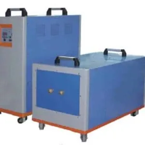
The Induction Billet Heating System is a complete, turnkey electromagnetic heating installation comprising four integrated subsystems: a solid-state IGBT induction power supply, a water-cooled induction heating coil (inductor), an automated billet handling and feed system, and a digital process control and monitoring platform. Together, these subsystems form a production-ready heating line capable of processing billets from ambient temperature to the required hot-working temperature in a controlled, repeatable, and fully automated manner.
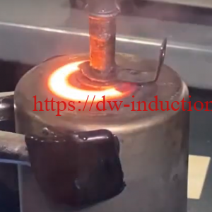
The power supply converts three-phase AC mains power to a high-current, medium-frequency AC output (typically 0.5–10 kHz for billet heating applications) using IGBT transistors in a full-bridge inverter topology. This output is delivered to the induction coil, which generates a powerful alternating magnetic field. When a conductive billet is placed inside the coil bore, eddy currents are induced throughout the billet cross-section, generating heat internally via the Joule effect. Unlike surface heating applications, billet heating requires through-heating — uniform temperature from surface to core — which is achieved by selecting a frequency low enough that the electromagnetic skin depth is comparable to or greater than the billet radius.
Systems are available in single-station batch configurations for low-volume or prototype production, and in multi-station continuous inline configurations for high-volume forging and rolling lines processing hundreds of billets per hour. Power ratings range from 50 kW for small-diameter bar heating to 3,000 kW or more for large steel billet heating lines feeding heavy forging presses.
Key Applications
The Induction Billet Heating System is the preferred heating solution for the following industrial applications:
- Hot Forging Preheat: Heating steel, aluminum, and titanium billets to forging temperature (900°C–1250°C for steel; 400°C–500°C for aluminum) before closed-die or open-die forging. The most common and highest-volume application for induction billet heaters worldwide.
- Aluminum Extrusion Billet Heating: Heating aluminum alloy billets (Ø100–300 mm) to extrusion temperature (420°C–520°C) with a controlled temperature gradient (front end hotter than back end) to compensate for die exit temperature variation and achieve uniform extrudate properties.
- Rolling Mill Billet Preheat: Heating steel billets and blooms before hot rolling in rod, bar, and section mills. Induction heating is used for both full-length billet heating and localized end-heating for crop-end reduction.
- Copper and Brass Billet Heating for Extrusion: Heating copper alloy billets to 700°C–900°C before indirect or direct extrusion of tubes, rods, and profiles. Induction heating eliminates the surface oxidation (scale) that contaminates copper extrusion tooling in gas furnaces.
- Titanium Billet Heating for Aerospace Forging: Heating titanium alloy billets (Ti-6Al-4V and other aerospace grades) to 900°C–980°C in a controlled atmosphere or with rapid transfer to minimize oxidation before precision forging of aerospace structural components.
- Billet Reheating in Continuous Casting Lines: Reheating continuously cast billets that have cooled below the required rolling temperature, enabling direct hot charging without full reheating in a gas furnace.
- Warm Forming Preheat: Heating billets to intermediate temperatures (200°C–600°C) for warm forging of high-strength steels and aluminum alloys, where reduced forming forces and improved material flow are required without full hot-working temperatures.
- Induction Billet Heating for Pipe and Tube Manufacturing: Heating round billets before piercing and elongation in seamless pipe and tube mills.
Suitable Materials
The following materials are routinely processed in Induction Billet Heating Systems:
| Material | Grade / Standard | Heating Temperature Range | Frequency Range | Notes |
|---|---|---|---|---|
| Carbon Steel | AISI 1020–1060, S45C, C45 | 1100°C – 1250°C | 0.5 – 3 kHz | Most common billet material. High μr below Curie point accelerates initial heating. Scale formation minimal vs. gas furnace. |
| Alloy Steel | AISI 4140, 4340, 8620, SCM440 | 1100°C – 1200°C | 0.5 – 3 kHz | Higher alloy content may require slower heating rate to avoid thermal shock in large cross-sections. |
| Stainless Steel | AISI 304, 316, 410, 17-4PH | 1100°C – 1200°C | 1 – 5 kHz | Non-magnetic (austenitic grades); μr=1 requires higher frequency or higher power for equivalent heating rate. |
| Aluminum Alloys | AA6061, AA6082, AA7075, AA2024 | 420°C – 530°C | 0.5 – 2 kHz | Low resistivity and μr=1 require high power and low frequency for large billets. Taper heating profile for extrusion. |
| Copper and Brass | C11000, C26000, CuZn30, CuZn37 | 700°C – 900°C | 1 – 4 kHz | Very low resistivity (copper); requires high power density. Induction eliminates scale vs. gas furnace — critical for extrusion die life. |
| Titanium Alloys | Ti-6Al-4V (Grade 5), Ti-3Al-2.5V | 900°C – 980°C | 1 – 5 kHz | Moderate resistivity; non-magnetic. Rapid transfer to press essential to minimize oxidation. Argon atmosphere enclosure recommended for premium aerospace parts. |
| Nickel Alloys | Inconel 718, Waspaloy, Nimonic 90 | 1050°C – 1180°C | 1 – 5 kHz | High resistivity; good induction coupling. Tight temperature control (±10°C) critical to avoid incipient melting of low-melting phases. |
| Tool Steel | H13, D2, M2, P20 | 1050°C – 1150°C | 0.5 – 2 kHz | Slow heating rate recommended for large cross-sections to avoid thermal cracking. Preheat to 400°C before rapid heating to forging temperature. |
Working Principle
The Induction Billet Heating System operates on the principle of electromagnetic induction combined with resistive (Joule) heating. The IGBT power supply generates a medium-frequency alternating current that flows through the water-cooled induction coil, creating a rapidly alternating magnetic field within the coil bore. When a conductive billet is inserted into this field, the alternating flux induces circulating eddy currents throughout the billet volume according to Faraday’s Law of Electromagnetic Induction.
These eddy currents, flowing through the electrical resistance of the billet material, generate heat internally and uniformly throughout the billet cross-section via the Joule effect (P = I²R). The depth to which the induced currents penetrate is governed by the skin depth formula:
δ (mm) = 503 × √( ρ / (μr × f) )
For billet through-heating, the operating frequency is selected so that the skin depth δ is comparable to the billet radius R — specifically, the ratio R/δ should be in the range of 2–4 for efficient through-heating. At R/δ < 2, the billet is heated very uniformly but coupling efficiency is low. At R/δ > 4, heating is concentrated at the surface and a temperature gradient develops between surface and core.
For ferromagnetic steel billets, an important physical transition occurs at the Curie temperature (~760°C): the steel changes from ferromagnetic (high μr, small skin depth, rapid surface heating) to paramagnetic (μr = 1, large skin depth, more uniform heating). This transition is self-regulating — the heating pattern automatically shifts from surface-concentrated to more uniform as the billet heats through the Curie point, promoting temperature equalization between surface and core in the upper temperature range.
In addition to Joule heating, ferromagnetic materials below the Curie temperature also contribute a hysteresis heating component, where energy is dissipated in the repeated magnetic domain reversals driven by the alternating field. This component can contribute 10–30% of the total heating power in the sub-Curie temperature range, further accelerating the initial heating phase.
The total power required to heat a billet is calculated from the thermal energy equation:
P (kW) = m × Cp × ΔT / (t × η)
Where m is billet mass (kg), Cp is specific heat capacity (kJ/kg·°C), ΔT is the required temperature rise (°C), t is the heating time (seconds), and η is the system efficiency (typically 0.85–0.92 for induction billet heaters).
Technical Specifications
| Parameter | Specification | Notes |
|---|---|---|
| Rated Output Power | 50 kW – 3,000 kW | Continuously adjustable 10%–100%; custom ratings available |
| Frequency Range | 0.5 kHz – 10 kHz | Auto-tuning resonant circuit; optimal frequency matched to billet diameter and material |
| Input Voltage | 3-phase 380V / 415V / 660V / 6kV / 10kV | Medium voltage input for large systems (>500 kW) |
| Overall Efficiency | 88% – 93% | IGBT full-bridge topology; higher than SCR-based systems |
| Power Factor | ≥ 0.93 | Active power factor correction on large systems |
| Temperature Uniformity | ±10°C – ±20°C (surface to core) | Achieved after soak time; dependent on billet diameter and material |
| Max Billet Temperature | Up to 1350°C (steel) | Coil design and refractory lining rated for continuous operation at max temperature |
| Billet Diameter Range | Ø20 mm – Ø400 mm | Coil bore sized to billet diameter; quick-change coil system available |
| Billet Length Range | 50 mm – 2000 mm | Multi-coil series configuration for long billets |
| Heating Rate | 30 – 600 seconds per billet | Dependent on billet mass, material, target temperature, and power level |
| Throughput | 0.5 – 20 tonnes/hour | Dependent on power level, billet size, and material |
| Cooling System | Closed-loop water cooling | Cooling water: 5–35°C inlet, flow rate 30–500 L/min depending on power level |
| Coil Material | Copper tube, water-cooled, refractory-lined | Coil life >5,000 hours with proper maintenance |
| Control System | PLC + 10″ HMI touchscreen | Recipe management, data logging, remote monitoring |
| Communication Interfaces | Modbus RTU/TCP, Profibus, EtherNet/IP, OPC-UA | Full MES/SCADA integration capability |
| Protection Class | IP21 (standard); IP54 (optional) | IP54 for dusty forge shop environments |
| Dimensions (Power Supply) | 1200 × 800 × 1800 mm (W×D×H) typical for 200 kW | Larger systems in multi-cabinet configuration |
| Compliance | CE, ISO 9001:2015, RoHS | UL/CSA available for North American market |
Recommended Model Selection
| Application | Material | Billet Diameter | Recommended Power | Frequency | Notes |
|---|---|---|---|---|---|
| Small parts forging preheat | Carbon steel | Ø20 – Ø50 mm | 50 – 150 kW | 3 – 8 kHz | Single-station or small rotary table line |
| Medium forging line preheat | Carbon / alloy steel | Ø50 – Ø100 mm | 150 – 400 kW | 1 – 4 kHz | Continuous inline with conveyor feed |
| Heavy forging press preheat | Alloy steel / tool steel | Ø100 – Ø200 mm | 400 – 1000 kW | 0.5 – 2 kHz | Multi-coil series configuration; soak station required |
| Large billet forging (hydraulic press) | Alloy steel / stainless steel | Ø200 – Ø400 mm | 1000 – 3000 kW | 0.5 – 1 kHz | Medium voltage input; dedicated cooling tower |
| Aluminum extrusion billet heating | AA6061 / AA6082 | Ø100 – Ø250 mm | 200 – 800 kW | 0.5 – 1.5 kHz | Taper heating profile; front-end temperature 10–30°C higher than back end |
| Copper billet extrusion heating | C11000 / CuZn30 | Ø80 – Ø200 mm | 200 – 600 kW | 1 – 3 kHz | High power density required due to low resistivity of copper |
| Titanium aerospace billet heating | Ti-6Al-4V | Ø50 – Ø150 mm | 100 – 400 kW | 1 – 4 kHz | Argon atmosphere enclosure; rapid transfer system to press |
| Warm forging preheat | High-strength steel / aluminum | Ø30 – Ø100 mm | 50 – 200 kW | 2 – 6 kHz | Target temperature 200°C–600°C; precise temperature control critical |
Process Workflow
A standard induction billet heating process follows the workflow below:
- Billet Preparation and Loading:
Billets are cut to the required length by a sawing or shearing station upstream. They are inspected for dimensional conformance and surface condition. Billets are loaded onto the infeed conveyor or magazine feeder, either manually for low-volume lines or automatically via a robotic loading system for high-volume lines. - Recipe Selection and System Initialization:
The operator selects the appropriate heating recipe from the HMI touchscreen based on the billet material, diameter, length, and target temperature. The system verifies cooling water flow, power supply status, and coil condition before initiating the heating cycle. For automated lines, recipe selection is triggered automatically by a barcode or RFID reader on the billet or production order.
- Billet Feed into Heating Coil:
The billet is advanced into the induction coil bore by the feed mechanism (pusher, walking beam, or roller conveyor). For continuous heating lines, billets are fed end-to-end through a multi-coil tunnel, with each billet advancing one position as the heated billet exits at the discharge end. - Heating Phase:
The induction power supply energizes the coil and heats the billet according to the programmed power-time profile. For steel billets, a two-stage heating profile is typically used: high power in the initial phase (below Curie temperature, where coupling is most efficient) followed by a reduced-power soak phase (above Curie temperature) to allow temperature equalization between surface and core. - Temperature Measurement and Verification:
An infrared pyrometer or thermal imaging camera measures the billet surface temperature at the coil exit. The measured temperature is compared to the recipe setpoint. Billets outside the acceptable temperature window (typically ±20°C of target) are automatically rejected by a diverter gate and returned for reheating or scrapped, depending on the deviation. - Billet Discharge and Transfer:
Accepted billets are discharged from the coil exit and transferred to the forging press, extrusion press, or rolling mill by a high-speed transfer conveyor, robot, or manipulator. Transfer time is minimized to reduce temperature loss and oxidation — typically less than 10 seconds from coil exit to die contact. - Hot-Working Operation:
The heated billet is formed in the forging press, extrusion press, or rolling mill. The induction heating system is synchronized with the press cycle to ensure a heated billet is available at the press at the required rate, maintaining continuous production without press idle time. - Data Logging and Traceability:
All process parameters for each billet — heating time, power profile, exit temperature, billet ID, and any alarms — are logged to the system database. Data is transmitted to the factory MES for full production traceability and quality records.

Coil and Fixture Design
The induction coil is the most application-specific and performance-critical component of the billet heating system. For billet through-heating, the standard coil geometry is a multi-turn solenoid wound from rectangular-section copper tubing (internally water-cooled), with a refractory ceramic liner to protect the coil from radiant heat and billet contact.
Coil Bore Diameter
The coil bore diameter is typically 1.15–1.25× the billet outer diameter. A smaller gap improves electromagnetic coupling efficiency but reduces tolerance for billet dimensional variation and increases the risk of billet-to-coil contact. For automated lines processing billets with tight diameter tolerances (±1 mm), a bore-to-billet ratio of 1.15 is standard. For manual loading or billets with wider diameter tolerances, 1.25 is recommended.
Coil Length and Number of Turns
The coil length is determined by the required heating time and the billet feed speed. For continuous tunnel heating, the coil length equals the billet length for single-billet-in-coil configurations, or is a multiple of the billet length for multi-billet configurations. The number of turns is optimized to match the coil impedance to the power supply output impedance for maximum power transfer efficiency.
Refractory Lining
The inner surface of the coil is lined with a high-temperature refractory material (typically castable alumina or zirconia-based refractory, rated to 1400°C+) to protect the copper coil from radiant heat, scale, and occasional billet contact. The refractory lining also provides electrical insulation between the billet and the coil. Lining thickness is typically 15–30 mm, balancing thermal insulation with coil bore diameter constraints.
Multi-Coil Series Configuration
For high-power systems or long billets, multiple coils are connected in series along the billet travel path. This allows the heating to be distributed across multiple stations, with each coil operating at a manageable power level. A soak station (unpowered insulated tunnel) between the heating coils allows temperature equalization between surface and core before the billet exits the system.
Taper Heating Coil for Aluminum Extrusion
Aluminum extrusion requires a controlled temperature gradient along the billet length (front end 10–30°C hotter than the back end) to compensate for die exit temperature variation. This is achieved using a tapered power distribution coil, where the turn density or coupling distance varies along the coil length, or by using a multi-zone coil with independently controlled power zones.
Control System and Automation
The control system of the Induction Billet Heating System integrates power regulation, temperature measurement, billet tracking, feed mechanism control, and data management into a unified digital platform.
IGBT Power Supply Control
A 32-bit DSP controller manages the IGBT gate drive signals, implementing phase-shift PWM control to regulate output power with a response time of less than 2 ms. The resonant auto-tuning circuit continuously adjusts the operating frequency to maintain resonance as the coil impedance changes with billet temperature, ensuring maximum power transfer efficiency throughout the heating cycle.
Temperature Measurement and Closed-Loop Control
Billet exit temperature is measured by a two-color infrared pyrometer (operating range 600°C–1400°C for steel, 200°C–600°C for aluminum) mounted at the coil exit. The pyrometer signal feeds a PID controller that adjusts the power supply output to maintain the target exit temperature. For large-diameter billets where surface-to-core temperature gradients are significant, a thermal model (software-based) estimates the core temperature from the surface measurement and heating history, enabling core temperature control without physical contact.
Billet Tracking and Feed Control
Each billet is tracked through the heating system by a combination of position sensors (photoelectric or inductive proximity sensors) and a PLC-based billet tracking algorithm. The feed mechanism speed is synchronized with the press cycle to ensure a heated billet arrives at the press at the correct time. Billet ID (from upstream barcode or RFID) is linked to the heating data record for full traceability.
HMI and Recipe Management
A 10-inch color touchscreen HMI provides operator access to recipe management (up to 1,000 recipes), real-time process monitoring (power, temperature, feed speed, billet count), alarm management, and production reporting. Recipes define the complete heating profile: power ramp rate, maximum power, target exit temperature, acceptable temperature window, feed speed, and atmosphere control parameters.
MES Integration and Industry 4.0
The system communicates with the factory MES via OPC-UA, Modbus TCP, or EtherNet/IP. Real-time data streams include per-billet heating records, energy consumption per tonne, system availability (OEE), and predictive maintenance indicators (coil temperature, cooling water quality, IGBT junction temperature). Remote monitoring and diagnostics are available via secure VPN connection to HLQ’s service center.
Common Problems and Solutions
| Problem | Cause | Solution |
|---|---|---|
| Non-uniform temperature — hot surface, cold core | Frequency too high; R/δ ratio too large; insufficient soak time | Reduce frequency; add soak station after heating coil; extend heating cycle with reduced power in final phase |
| Non-uniform temperature — hot ends, cold middle | End effect: magnetic flux concentration at billet ends induces higher current density at ends than in the middle of the coil | Use flux concentrators (ferrite) at coil center; use end-compensation coil design; adjust power profile |
| Billet surface overheating / melting | Power density too high; heating rate too fast; frequency too high | Reduce power; lower frequency; use two-stage heating profile (high power below Curie, reduced power above Curie) |
| Excessive scale formation on billet surface | Heating time too long; billet temperature too high; air atmosphere | Optimize heating cycle to minimize time above 900°C; consider nitrogen atmosphere enclosure for scale-sensitive applications |
| Poor coupling efficiency / slow heating | Coil bore too large relative to billet diameter; frequency mismatch; refractory lining cracked | Replace coil with correct bore size; retune resonant circuit; inspect and repair refractory lining |
| IGBT over-temperature alarm / shutdown | Cooling water flow insufficient; water temperature too high; IGBT module aging | Check cooling water flow rate and inlet temperature; clean heat exchangers; test IGBT modules; replace if necessary |
| Billet temperature below setpoint at coil exit | Power supply output limited; billet feed speed too high; material property variation | Reduce feed speed; verify power supply is delivering rated output; check for coil damage or refractory degradation |
| Inconsistent billet temperature batch-to-batch | Billet material property variation (ρ, μr); dimensional variation; pyrometer calibration drift | Tighten incoming material specification; recalibrate pyrometer; implement closed-loop temperature control with per-billet feedback |
| Coil refractory lining cracking or spalling | Thermal shock from rapid heating/cooling cycles; billet contact; refractory quality | Implement controlled warm-up and cool-down procedures; use billet guides to prevent contact; upgrade to higher-quality refractory |
Engineering Selection Guide
Step 1: Define the Billet Parameters
Establish the billet material, diameter (D), length (L), and mass (m). These are the primary inputs to all subsequent calculations. For lines processing multiple billet sizes, identify the full range and design for the most demanding case (typically the largest diameter and highest-temperature material).
Step 2: Calculate Required Power
Use the thermal energy formula: P (kW) = m × Cp × ΔT / (t × η). For a steel billet of 10 kg heated from 20°C to 1200°C (ΔT = 1180°C) in 120 seconds, with Cp = 0.65 kJ/kg·°C and η = 0.90: P = 10 × 0.65 × 1180 / (120 × 0.90) = 71 kW. For a production line processing 10 billets per hour, the average power requirement is 71 kW × (10 × 120/3600) = 23.7 kW average, but the installed power must cover the peak demand of one billet heating simultaneously.
Step 3: Select Operating Frequency
Calculate the skin depth at process temperature using: δ (mm) = 503 × √(ρ / (μr × f)). For through-heating, target R/δ = 2–4 (where R is the billet radius). For a 100 mm diameter steel billet (R = 50 mm) at 900°C (ρ = 110 μΩ·cm, μr = 1), targeting R/δ = 3: δ = 50/3 = 16.7 mm. Solving for f: f = 25.3 × 110 / (1 × 16.7²) = 10.0 kHz. However, for large billets, 1–3 kHz is the practical range — verify that R/δ is acceptable at the selected frequency.
Step 4: Confirm Throughput Requirements
Calculate the required throughput in billets per hour and tonnes per hour. Verify that the selected power level and heating cycle time are compatible with the press or extrusion cycle time. For continuous lines, the induction system must deliver heated billets at a rate equal to or greater than the downstream process consumption rate, with a buffer of at least 10–15% to accommodate process variation.
Step 5: Specify Automation Level
Define the required level of automation: manual batch (operator loads and unloads billets), semi-automatic (automatic feed, manual unload), or fully automatic (robotic loading, automatic transfer to press, full MES integration). Automation level significantly affects system cost and lead time but also determines achievable throughput, temperature consistency, and labor cost.
Step 6: Consider Special Requirements
Identify any special requirements: taper heating profile (aluminum extrusion), atmosphere control (titanium, stainless steel), temperature gradient measurement (large billets), quick-change coil system (multi-product lines), or integration with existing press control systems. Document these requirements in the equipment specification before requesting quotations.
Advantages
- High Energy Efficiency: Overall system efficiency of 88–93% versus 40–55% for gas-fired furnaces, resulting in energy cost savings of 40–60% per tonne of heated material.
- Minimal Scale Formation: Rapid heating cycle (seconds to minutes versus hours in gas furnaces) dramatically reduces the time the billet surface is exposed to oxidizing atmosphere at high temperature. Scale losses of 0.1–0.3% versus 1–3% for gas furnaces, saving material and reducing die wear.
- Precise Temperature Control: Closed-loop pyrometer control achieves exit temperature accuracy of ±10–20°C, ensuring consistent forging or extrusion conditions and reducing scrap from over- or under-temperature billets.
- Fast Startup and Shutdown: Induction systems reach full operating power in less than 30 seconds from cold start, versus 2–8 hours for gas furnaces. Instant shutdown with no residual heat loss during production breaks.
- Compact Footprint: An induction billet heating line occupies 60–80% less floor space than an equivalent-capacity gas furnace, freeing valuable forge shop floor space.
- Zero Combustion Emissions: No NOx, CO, CO₂, or particulate emissions from the heating process itself. Supports carbon neutrality goals and eliminates the need for combustion air management and flue gas treatment systems.
- Automation Compatible: Direct integration with robotic loading/unloading systems, press controls, and MES platforms. Enables fully automated, lights-out production with complete per-billet traceability.
- Consistent, Repeatable Results: Digital recipe management ensures identical thermal cycles for every billet, every shift, every day — regardless of operator skill level.
- Low Maintenance: No burners, refractory furnace chambers, combustion controls, or flue systems to maintain. Primary maintenance items are coil refractory lining (annual) and cooling water quality management.
- Safe Working Environment: No open flames, no combustion gases, no hot furnace chamber surfaces. Significantly lower workplace temperature in the forge shop compared to gas furnace operation.
Limitations
- Higher Capital Cost: The initial capital cost of an induction billet heating system is typically 1.5–3× higher than an equivalent gas furnace. This premium is recovered through energy savings and reduced scale losses within 2–4 years in most applications.
- Limited to Conductive Materials: Induction heating is only applicable to electrically conductive materials. Non-conductive billets (ceramics, polymers) cannot be heated by induction.
- Frequency Constraint for Large Billets: Very large billets (Ø300 mm+) require very low frequencies (0.5–1 kHz) for adequate penetration depth. Power supplies at these frequencies are large, expensive, and require medium-voltage input infrastructure.
- Coil Specificity: Each coil is designed for a specific billet diameter range. Processing billets of significantly different diameters requires coil changeover, which takes 30–120 minutes depending on the system design. Quick-change coil systems reduce this time but add cost.
- End Effect: The ends of billets in the induction coil experience a different magnetic field distribution than the middle, leading to higher current density (and higher temperature) at the billet ends. This end effect must be compensated by coil design or power profiling.
- Cooling Water Infrastructure: The system requires a reliable, clean cooling water supply. In facilities without existing water cooling infrastructure, a closed-loop chiller or cooling tower must be installed, adding to the total system cost.
- Electrical Power Quality: Large induction systems (500 kW+) can generate harmonic disturbances on the electrical supply network. Active harmonic filters or dedicated transformer feeds may be required to meet utility power quality standards.
Why Choose HLQ Induction Equipment?
HLQ Induction Equipment is a specialized manufacturer of solid-state induction heating systems with over 20 years of engineering experience in billet heating applications for the forging, extrusion, rolling, and metalworking industries. Our Induction Billet Heating Systems are installed in over 500 production facilities across 30 countries, processing steel, aluminum, copper, titanium, and nickel alloy billets in some of the world’s most demanding manufacturing environments.
- Complete Turnkey Systems: HLQ designs, manufactures, installs, and commissions complete billet heating lines — power supply, coil, feed system, control system, and MES integration — from a single source, eliminating multi-vendor coordination risk.
- Application Engineering: Our team of induction heating engineers performs free pre-sales application studies, including power calculations, frequency selection, coil design, and process simulation, for every new project.
- Custom Coil Design: HLQ designs and manufactures application-specific induction coils in-house, with full electromagnetic FEA simulation to optimize temperature uniformity before fabrication.
- Process Validation: Every system is validated with customer-supplied billets at HLQ’s test facility before shipment, with a full process report including temperature profiles, scale measurements, and energy consumption data.
- Global Service Network: HLQ maintains service centers and trained field engineers in Europe, North America, Southeast Asia, and China, with guaranteed 48-hour on-site response for critical production issues.
- Long-Term Support: 2-year equipment warranty, 10-year spare parts availability guarantee, and lifetime technical support from HLQ application engineers.

Related Articles
- Skin Effect in Induction Heating: How Frequency Determines Heating Depth
- Induction Billet Heating vs. Gas Furnace: A Full Engineering and Cost Comparison
- How to Calculate Power Requirements for Induction Billet Heating
- Taper Heating for Aluminum Extrusion Billets: Process Guide and Equipment Selection
- Induction Coil Design for Billet Through-Heating: Engineering Principles and Best Practices
- Temperature Measurement in Induction Billet Heating: Pyrometer Selection and Calibration
- Industry 4.0 Integration for Induction Billet Heating Lines: OPC-UA, MES and Data Logging
FAQ
Q1: What is the typical energy consumption of an induction billet heating system compared to a gas furnace?
A: An induction billet heating system typically consumes 280–380 kWh of electrical energy per tonne of steel heated to 1200°C, compared to 350–500 kWh equivalent (as natural gas) for a modern gas furnace. However, since electrical energy is more expensive per kWh than gas in most markets, the operating cost comparison depends on local energy prices. In markets where electricity costs less than 2.5× the gas price per equivalent kWh, induction heating is typically more cost-effective when scale savings, reduced maintenance, and higher throughput are included in the total cost of ownership analysis.
Q2: How long does it take to change the induction coil when switching to a different billet diameter?
A: With a standard coil connection system, coil changeover takes 60–120 minutes including disconnection of water and electrical connections, coil removal, new coil installation, reconnection, and system verification. With HLQ’s optional quick-change coil connector system, changeover time is reduced to 15–30 minutes. For high-mix production lines processing multiple billet diameters, we recommend the quick-change system and maintaining a dedicated coil for each billet diameter range.
Q3: Can the system heat billets with surface defects, cracks, or scale from previous operations?
A: Surface scale and minor surface defects do not significantly affect induction heating performance, as the induced currents penetrate below the surface layer. However, deep surface cracks can cause local current concentration and hot spots at the crack tips, potentially leading to crack propagation during heating. Billets with significant surface defects should be conditioned (ground or turned) before induction heating. Heavy pre-existing scale should be removed to ensure accurate pyrometer temperature measurement.
Q4: What is the minimum and maximum billet diameter that can be processed?
A: HLQ induction billet heating systems are available for billet diameters from Ø20 mm (small bar heating for fastener forging) to Ø400 mm (large billet heating for heavy forging presses). For diameters below Ø20 mm, the workpiece is typically classified as bar or rod stock and handled by a wire/bar heating system with a different feed mechanism. For diameters above Ø400 mm, custom systems with medium-voltage power supplies (6 kV or 10 kV input) are required — contact HLQ engineering for a custom application study.
Q5: How is temperature uniformity verified across the billet cross-section?
A: Surface temperature is measured continuously by an infrared pyrometer at the coil exit. Core temperature is estimated by a thermal model running in the PLC, which calculates the temperature distribution based on the measured surface temperature, heating time, power history, and material thermal conductivity. For critical applications (aerospace titanium, nickel alloy forgings), a validation study is performed during commissioning: billets are heated under production conditions, immediately sectioned, and thermocouple measurements are taken at the surface, mid-radius, and center to verify the thermal model accuracy and confirm temperature uniformity meets specification.
Q6: What happens if the press stops and a billet remains in the coil?
A: The control system continuously monitors the press cycle status. If the press stops (planned or unplanned), the induction system automatically switches to a low-power “holding” mode that maintains the billet at a reduced temperature (typically 50–100°C below the target forging temperature) to prevent overheating while minimizing scale formation. If the press stop exceeds a configurable time limit (typically 5–15 minutes), the system automatically ejects the billet and flags it for inspection. The operator can then decide to reheat the billet or scrap it based on the temperature history log.
Q7: Is an induction billet heating system suitable for a small forge shop with low production volumes?
A: Yes. HLQ offers compact, single-station induction billet heating systems starting from 50 kW, suitable for small forge shops processing 1–20 billets per hour. These systems have a lower capital cost, smaller footprint, and simpler installation than large continuous lines. For very low volumes (prototype or job shop work), a manually loaded single-station system with a standard HMI is the most cost-effective solution. The energy efficiency and scale reduction benefits of induction heating apply equally at low production volumes, and the fast startup time (versus hours for a gas furnace) is particularly valuable for job shops that heat billets intermittently.