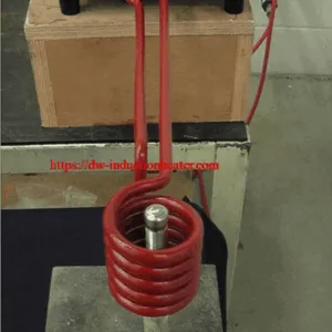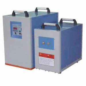
Full solid state induction heater
35 kW Full Solid State Induction Heater — HLQ DW-MF-35kW
Quick Answer
The HLQ DW-MF-35kW is a medium frequency full solid state induction heater. The product page lists an IGBT inverter, a maximum oscillating power of 35 kW, a frequency range of 1–20 kHz, and separate generator and transformer dimensions.
Its listed applications include rod heating for forging, stator or rotor heating for fitting, tube-end heating for extrusion, mold heating, shaft and gear heat treatment, tempering and weld-joint preheating. Each application requires a compatible coil, workpiece arrangement and validated process.
Important specification distinction: the published 35 kW rating and 380 V / 51 A input figures require clarification before electrical installation design. They should not be interpreted as a verified continuous output condition without supporting equipment documentation.

| Item | Published value |
|---|---|
| Model | DW-MF-35kW |
| Maximum oscillating power | 35 kW |
| Oscillating frequency | 1–20 kHz |
| Supply | Three-phase 380 V, 50/60 Hz |
| Maximum input current | 51 A; rating conditions require confirmation |
| Cooling water | Greater than 0.2 MPa; 6 L/min listed flow |
| Published cable length | 2 m |
Table of Contents
What Is the Full Solid State Induction Heater?
A full solid state induction heater uses semiconductor power electronics to supply alternating electrical energy to an induction heating assembly. For the DW-MF-35kW, the original description identifies an IGBT inverter with a parallel circuit arrangement.
The term “solid state” describes the power-conversion technology. It does not establish the workpiece temperature, heating efficiency, production rate or suitability for every metal-heating process.
The product table identifies both a generator and a transformer. Coil design, temperature measurement, fixtures and material handling must be defined for the intended application. The page does not publish a complete accessory or delivery list.
The broader medium frequency induction heating equipment range provides context for selecting a suitable power source and process arrangement.

Key Applications
The original page lists several heating duties. These are application categories rather than guaranteed production capacities for a particular workpiece.
| Application | Heating objective | Information needed |
|---|---|---|
| Rod heating for forging | Heat a rod or rod end before forming | Material, diameter, heated length, target temperature and required cycle |
| Stator or rotor fitting | Heat a component to support the specified assembly process | Required expansion, assembly clearances and component temperature limits |
| Tube-end heating for extrusion | Heat a defined tube-end region | Alloy, wall thickness, heated length and forming conditions |
| Mold heating | Heat a conductive mold or selected mold region | Geometry, coil access and allowable temperature distribution |
| Shaft and gear heat treatment | Provide heat for a specified treatment | Material grade, treatment objective, quench method and acceptance criteria |
| Tempering | Apply the required thermal cycle | Temperature measurement, holding conditions and material requirements |
| Weld-joint preheating | Heat the designated joint area before welding | Approved process temperature, heated zone and monitoring method |
| Melting | Provide energy to a compatible melting assembly | Metal, charge mass, furnace arrangement and validated melt cycle |
For rod and billet duties, review the induction forging applications collection. The MF-35 page does not specify a maximum rod diameter, kilograms per hour or guaranteed forging temperature.
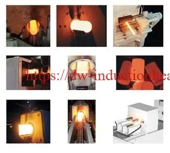
Application Assessment Examples
A rod-end heating assessment should verify the required temperature profile before forming. A fitting assessment should evaluate expansion and the temperature limits of the entire assembly. A tube-end heating assessment should check the temperature distribution through the wall and along the heated section.
These are engineering assessment examples based on the listed applications. No customer identity, workpiece dimensions or trial results are implied.
Suitable Materials
Direct induction heating requires an electrically conductive workpiece. Material resistivity, magnetic behavior, section size, temperature and coil coupling affect the heating response. The original MF-35 page does not provide a qualified material-grade list.
| Material group | Technical basis | Selection boundary |
|---|---|---|
| Carbon and alloy steels | Conductive materials relevant to forging and heat-treatment duties | Hardening response depends on grade and the complete thermal and quenching process |
| Stainless steels | Electrically conductive, with magnetic behavior varying by grade | Confirm the actual alloy and application rather than assuming carbon-steel behavior |
| Copper and brass | Conductive nonmagnetic materials can develop induced currents | Assess coil coupling, heat losses and the required cycle |
| Aluminum | Conductive material that can be heated in a suitable induction assembly | No MF-35-specific aluminum batch capacity or heating time is published |
| Mixed-material assemblies | A conductive part may heat adjacent components through heat transfer | Check insulation, seals, coatings and other temperature-sensitive components |
| Nonconductive material alone | Does not provide the direct eddy-current heating path described here | No indirect-heating arrangement is specified for this model |
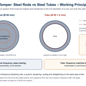
For induction hardening applications, a suitable steel grade and a validated quenching process are essential. A 35 kW equipment rating does not establish hardness or hardened depth.
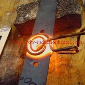
Related heat-treatment illustration retained from the original page
Working Principle
The generator supplies alternating electrical energy to a matched heating assembly. Current in the induction coil produces a changing magnetic field. This field induces currents in the conductive workpiece, where electrical resistance converts energy into heat.
The transformer and coil must be compatible with the generator and load. The original page identifies a parallel IGBT inverter arrangement but does not publish an internal circuit diagram.
The general induction heating principle explains the relationship between the electrical supply, coil field and conductive load.
| Stage | Function | Engineering significance |
|---|---|---|
| Incoming supply | Provides three-phase electrical power | Must match the actual equipment nameplate and installation requirements |
| IGBT power conversion | Supplies alternating energy to the heating assembly | The published power definition requires confirmation |
| Transformer and matching arrangement | Interfaces the power source with the load | Must suit the operating coil and workpiece |
| Induction coil | Creates the changing magnetic field | Shape and position influence heating distribution |
| Conductive workpiece | Develops heat through induced currents | Material properties and thermal conduction influence the result |
| Cooling circuit | Removes heat from cooled equipment components | Flow and pressure must be checked at the specified locations |
For otherwise comparable material conditions, lower frequency generally increases electromagnetic penetration depth. Final temperature distribution also depends on heating time and thermal conduction. Frequency alone is not a prediction of the final treatment depth.
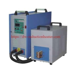
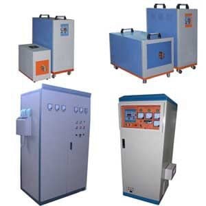
Related induction power equipment retained from the original page
Technical Specifications
The following table preserves the values published on the MF-35 product page. Unspecified definitions remain identified rather than being filled with assumptions.
| Parameter | Published value | Interpretation or clarification |
|---|---|---|
| Model | DW-MF-35kW | Original designation normalized for unit formatting |
| Input supply | Three-phase 380 V, 50/60 Hz | No supply-voltage tolerance is stated |
| Maximum oscillating power | 35 kW | Not automatically equivalent to continuous absorbed workpiece power |
| Maximum input current | 51 A | Requires reconciliation with the published power rating |
| Oscillating frequency | 1–20 kHz | Actual operation depends on the matched configuration |
| Cooling-water pressure | Greater than 0.2 MPa | Pressure measurement location is not specified |
| Cooling-water flow | 6 L/min | Total-flow or individual-circuit allocation is not defined |
| Duty-cycle entry | 100%, 40°C | The meaning and test conditions of the 40°C reference are not defined |
| Generator dimensions | 560 × 270 × 470 mm | Dimension order is not labeled in the source |
| Transformer dimensions | 550 × 300 × 420 mm | Dimension order is not labeled in the source |
| Net weight | 42 kg / 50 kg | Component assignment is not explicitly stated |
| Cable length | 2 m | Endpoints and permitted extension arrangements are not specified |
Electrical Rating Check
For a balanced three-phase supply, apparent power is calculated as √3 × line voltage × line current. At 380 V and 51 A, the result is approximately 33.57 kVA.
Even at unity power factor and before conversion losses, 35 kW would require approximately 53.18 A at 380 V. This calculation identifies a need to clarify the published rating conditions; it does not authorize replacing the original 51 A entry with a different value.
Electrical protection, cable sizing and supply capacity should be based on the actual nameplate and approved installation documentation.
Verified Unit Conversions
| Source value | Converted value | Boundary |
|---|---|---|
| 1–20 kHz | 1,000–20,000 Hz | Frequency conversion only |
| 1–20 kHz | Oscillation periods from 1 ms to 50 µs | Electrical cycle periods, not workpiece heating times |
| Pressure greater than 0.2 MPa | Greater than 2 bar | Does not define a complete pump specification |
| 6 L/min | 360 L/h or 0.1 L/s | Does not establish cooling capacity without thermal conditions |
| 2 m cable length | 2,000 mm | Does not establish permitted cabinet spacing or cable routing |
| 380 V and 51 A, three-phase | Approximately 33.57 kVA | Balanced-supply apparent power, not measured heating output |
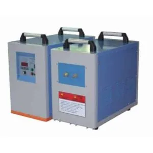
Related lower-power equipment image retained from the original page
Scope of the Original Catalogue Link
The original HLQ catalogue PDF is retained for reference. It describes a different air-cooled pre-weld and post-weld heating equipment family, rather than a dedicated DW-MF-35 specification sheet.
Its temperature ranges, control features, cooling arrangement and accessories should not be assigned to the MF-35 without separate model-specific documentation.
Information Not Specified on This Page
| Item | Published status |
|---|---|
| Coil quantity and geometry | No accessory list or coil drawing provided |
| Temperature sensor and accuracy | Not specified |
| Foot switch or other operator interface | Not specified as a supplied item |
| Cooling plant | Water requirements listed; cooling-unit supply scope not identified |
| PLC, touchscreen or automatic handling | Not specified for this model |
| Maximum workpiece temperature or size | Not published |
| Heating time, throughput and energy per part | No measured values published |
Recommended Model Selection
Use the MF-35 as a candidate for a defined heating duty. Select the generator together with the transformer, coil, material and required process result.
| Model | Published maximum oscillating power | Published frequency | Reference |
|---|---|---|---|
| DW-MF-15KW | 15 kW | 1–20 kHz | MF-15 product specifications |
| DW-MF-25KW | 25 kW | 1–20 kHz | MF-25 product specifications |
| DW-MF-35kW | 35 kW | 1–20 kHz | Current product page |
| DW-MF-45KW | 45 kW | 1–20 kHz | MF-45 product specifications |
This comparison reproduces published power classes. It does not establish proportional heating speed, equal efficiency, identical matching assemblies or automatic interchangeability.
| Requirement | Selection approach | Evidence needed |
|---|---|---|
| Localized heating | Match the coil to the required zone and access conditions | Workpiece drawing and trial temperature distribution |
| Greater heated mass or shorter cycle | Evaluate thermal demand and coupling before changing power class | Cycle data and actual load behavior |
| Specified treatment depth | Evaluate frequency, material, time and quenching together | Hardness profile and treatment acceptance results |
| Fitting duty | Check expansion and temperature limits of the full assembly | Assembly dimensions and validated fitting procedure |
| Melting duty | Specify the compatible furnace and charge conditions | Metal, charge mass and validated melt cycle |

Process Workflow
The following sequence supports application development. Machine operation must follow the instructions supplied with the actual equipment.
- Define the workpiece: record the material, dimensions, heated zone and starting condition.
- Define acceptance: specify the required temperature profile, forming condition, fitting result or treatment outcome.
- Match the equipment: establish the generator, transformer, coil and workpiece positioning.
- Verify utilities: confirm nameplate supply, cooling conditions and protection functions.
- Run a controlled trial: use approved settings and record the thermal response and cycle conditions.
- Validate and document: assess the result and record the approved settings, checks and shutdown procedure.
| Record | Purpose |
|---|---|
| Material and dimensions | Identify changes in the heating load |
| Coil and workpiece position | Control changes in coupling and heating distribution |
| Settings and cycle time | Define the actual trial conditions |
| Temperature measurement method | Make thermal results comparable |
| Process acceptance results | Verify the intended manufacturing outcome |
| Electrical energy and accepted output | Support measured energy-per-part evaluation |
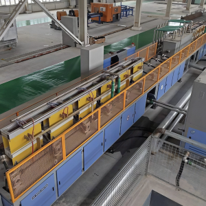
Separate production-line image retained from the original page
Common Problems and Solutions
The original description lists overvoltage, overcurrent, overheating, phase-loss and water-shortage alarm or protection functions. It does not provide fault codes or trip thresholds. The following checks are general engineering guidance.
| Observation | Check | Appropriate response |
|---|---|---|
| Heating is slower than expected | Workpiece changes, coil position, matching, applied power and heat losses | Compare conditions with the approved trial before changing the power class |
| Temperature is uneven | Coil geometry, workpiece geometry, positioning and measurement method | Review the heating pattern and validate the revised arrangement |
| Water-shortage indication | Supply condition, restrictions, leakage and indicated circuit | Stop heating and follow the supplied procedure to restore cooling |
| Overheating indication | Cooling conditions, load and the affected component | Identify the cause before restarting; keep protection functions active |
| Overcurrent indication | Connections, coil changes and load-matching condition | Use qualified assessment; do not bypass protection |
| Overvoltage or phase-loss indication | Incoming electrical supply and connections | Use the approved electrical data and qualified electrical inspection |
| Hardness or depth misses the target | Material grade, heating pattern, temperature history and quench | Reassess the complete treatment process |
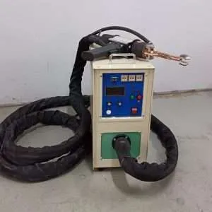
Separate handheld equipment image retained from the original page
Engineering Selection Guide
Define the process and installation scope before treating the MF-35 as a complete production solution. The page provides component dimensions and a cable length, but no approved installation drawing.
| Area | Information needed | Reason |
|---|---|---|
| Workpiece | Grade, geometry, mass and initial condition | Defines the electromagnetic and thermal load |
| Process target | Heated zone, temperature or treatment result and cycle requirement | Defines acceptance |
| Matching assembly | Transformer, coil and connection arrangement | Establishes electrical and mechanical compatibility |
| Power supply | Nameplate input, permissible voltage conditions and protection requirements | Resolves the published rating ambiguity |
| Cooling | Flow allocation, pressure location, water conditions and thermal load | Supports correct equipment operation |
| Layout | Cabinet locations, maintenance access and cable route | Cannot be inferred from the 2 m cable length alone |
| Measurement | Sensor type, measurement position and calibration method | Enables meaningful process verification |
| Supply scope | Controls, coils, cooling plant, fixtures and handling | No complete accessory list is published |
Application-specific induction heating coils must be matched to the generator, transformer and workpiece. Similar physical dimensions do not establish interchangeability.
The layout illustration is a functional planning sketch. It does not prescribe cabinet spacing, safety clearances, cooling connections or cable endpoints.
Performance Measurements
| Metric | Calculation | Required boundary |
|---|---|---|
| Average electrical input power | Measured electrical energy divided by elapsed time | Identify the equipment included in the measurement |
| Energy per accepted part | Measured kWh divided by accepted part count | Define treatment of warm-up and idle periods |
| Accepted production rate | Accepted part count divided by production time | State whether loading and unloading are included |
| Thermal consistency | Compare temperatures at specified positions and times | Use a consistent measurement method |
No numerical performance results are supplied because the product page does not publish the necessary measured inputs.
Related billet-line drawing retained from the original page

Advantages and Limitations
| Feature | Potential benefit | Condition or limitation |
|---|---|---|
| Solid state IGBT power conversion | Provides electrical energy for an induction heating process | The page does not quantify conversion or workpiece-heating efficiency |
| Medium frequency operation | Relevant to the listed forging, fitting and treatment applications | Actual heating depth depends on the material and complete process |
| Generator and transformer arrangement | Provides separate functional components for process integration | Connections and installation conditions require confirmation |
| Water cooling | Provides a means of removing equipment heat | Requires defined water conditions and a suitable cooling arrangement |
| Published 100% duty entry | Indicates a stated continuous-duty intention | Test conditions and the 40°C reference are not fully defined |
| Listed protection functions | Addresses several electrical and thermal fault conditions | Thresholds and installed implementation are not published |
| Multiple application categories | Supports evaluation for different manufacturing duties | Each duty needs its own tooling and process validation |
The available information does not support a universal energy-saving percentage, temperature accuracy, maximum workpiece size, heating time or hardened depth.
Separate pipe-forming equipment retained from the original page
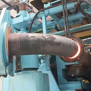
Why Choose HLQ?
HLQ publishes a named MF-35 model with electrical, cooling and component-size information. Its website also provides related induction equipment and application resources that support preliminary engineering assessment.
- A published DW-MF-35kW model and 1–20 kHz frequency range.
- Separate generator and transformer dimensions for preliminary planning.
- Listed cooling requirements and protection functions.
- Related product pages for comparing equipment power classes.
The original Medium Frequency Heating Machine category is retained for navigation.
A final specification should identify the actual rating definitions, component weights, matched coil, supplied controls and installation requirements. No certification, delivery package or service commitment is inferred from information that the product page does not provide.
6 Core FAQs
1. What does “full solid state” mean for this heater?
It describes the semiconductor-based power-conversion system. The MF-35 page identifies an IGBT inverter with a parallel circuit arrangement. The term does not establish the temperature, efficiency or production capacity of a particular application.
2. What power and frequency are published for DW-MF-35kW?
The page lists 35 kW maximum oscillating power and a frequency range of 1–20 kHz. The actual operating point depends on the matched equipment and load. The power definition requires clarification alongside the published input data.
3. Are the 380 V and 51 A figures sufficient for electrical installation design?
No. At nominal 380 V, a balanced three-phase current of 51 A corresponds to approximately 33.57 kVA. This does not establish a continuous 35 kW active output. Use the actual equipment nameplate and approved electrical documentation to resolve the rating conditions.
4. What cooling does the MF-35 require?
The product table specifies water pressure greater than 0.2 MPa and a flow of 6 L/min. It does not define the measurement point, circuit allocation, water quality or inlet temperature. The separate catalogue linked on the page describes different air-cooled equipment and should not override this model’s water requirements.
5. Can the MF-35 be used for fitting applications?
Heating stators or rotors for fitting is explicitly listed. Suitability depends on the assembly geometry, required expansion, coil arrangement and temperature limits. The induction shrink fitting applications collection provides related process context.
Separate joining-application image retained from the original page
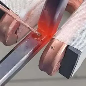
The original page also links to portable induction brazing equipment. That product is separate from the MF-35 configuration described here.
6. Does the page confirm supplied coils, controls and production performance?
No complete accessory list is published. The page identifies generator and transformer dimensions but does not state coil quantity, foot-switch supply, temperature-control hardware or automatic handling. It also provides no verified heating time, throughput, temperature accuracy or hardened-depth results for a specific workpiece.