

Aluminum Ingots Melting Furnace with Induction
Aluminum Ingot Melting Furnace with Induction
Quick Answer
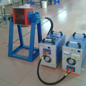
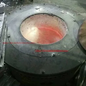
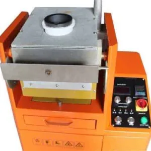
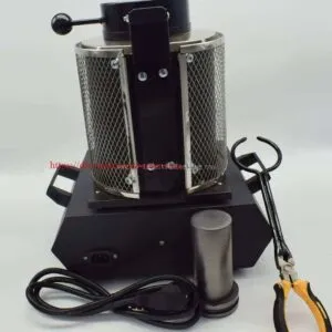
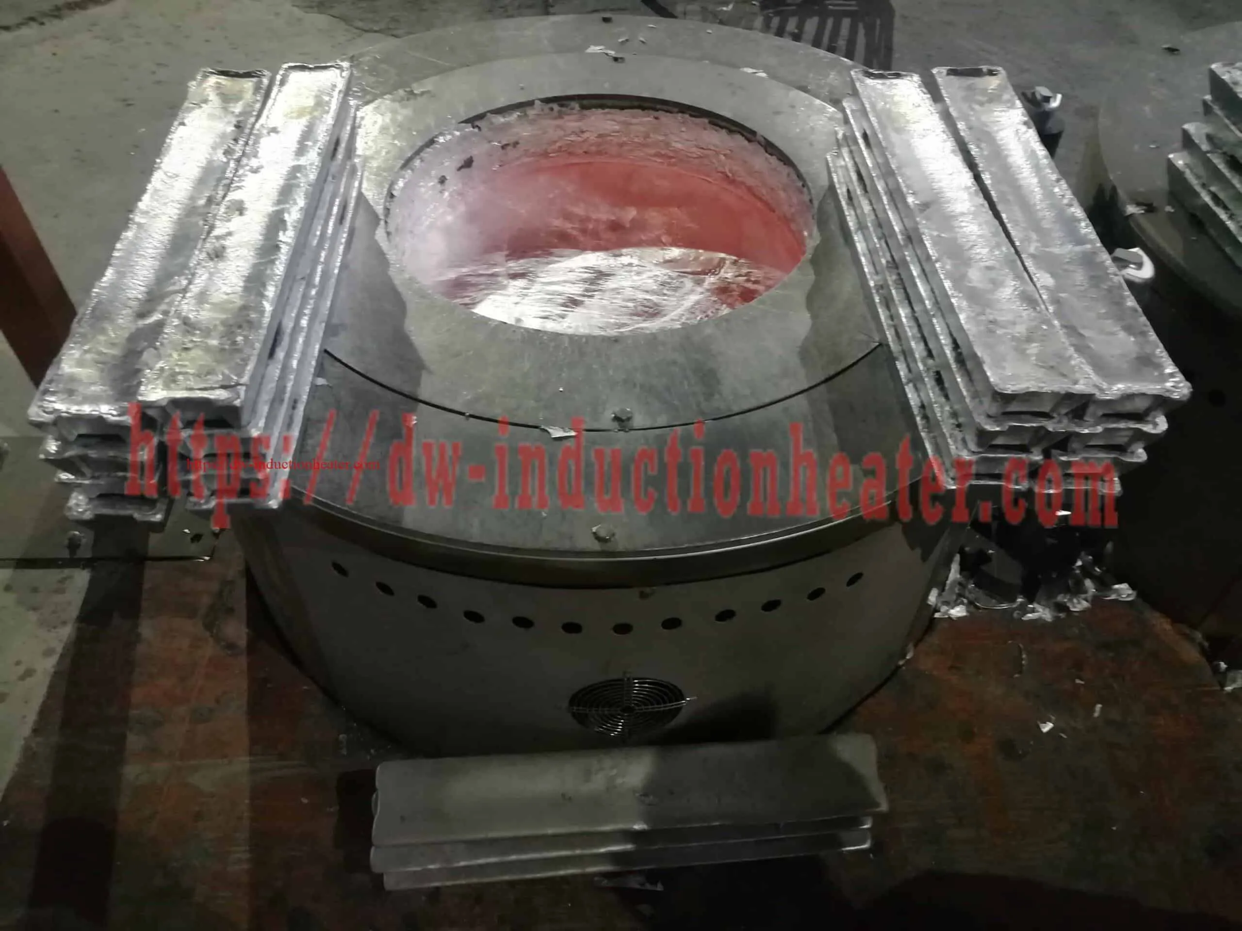
An aluminum ingot melting furnace converts solid aluminum or aluminum-alloy ingots into molten metal for a subsequent casting operation. HLQ’s published SMJD table lists aluminum capacities of 150–1200 kg and power figures of 60–200 kW. Ingot dimensions, individual ingot mass, alloy requirements and the complete melting-to-pouring cycle determine the appropriate configuration.
The capacity figures below are published reference values in kilograms. They do not specify hourly production. The linked manual describes an induction-heated conductive crucible that transfers heat to the aluminum.
Table of Contents
- Quick Answer
- What is the Aluminum Ingot Melting Furnace?
- Key Applications
- Suitable Materials
- Working Principle
- Technical Specifications
- Recommended Model Selection
- Process Workflow
- Common Problems and Solutions
- Engineering Selection Guide
- Advantages and Limitations
- Why Choose HLQ?
- 6 Core FAQs
What is the Aluminum Ingot Melting Furnace?
This electrically powered furnace is intended for remelting suitable aluminum ingots and aluminum-alloy charges. The process supplies liquid metal to the next production stage; it does not automatically refine an unidentified charge into pure aluminum.
For ingot-based production, selection starts with the actual ingot geometry and charge quantity. A furnace with sufficient nominal metal capacity may still require a different crucible or charging arrangement to accommodate the proposed ingots.
The broader range of aluminum melting furnaces provides related equipment options.
Key Applications
- Remelting identified aluminum ingots before mould filling.
- Preparing separate batches of specified aluminum-alloy ingots for casting.
- Matching repeated ingot-melting cycles to an established casting schedule.
- Assessing ingot melting as one stage of a wider foundry process.


For information on related line arrangements, see the aluminum ingot melting production line. Equipment shown on another product page should be evaluated separately from the configuration listed here.
Suitable Materials
| Charge category | Page context | Selection information |
|---|---|---|
| Aluminum ingots | Primary application of this page | Composition, lot identity, individual mass and dimensions |
| Aluminum-alloy ingots | Aluminum alloys appear in the published table | Alloy specification, required melt quality and casting procedure |
| Compatible aluminum scrap | Included in the original description | Composition compatibility, physical form and charge condition |
| Aluminum cans | Listed as an additional application | Separate assessment of preparation, coatings and handling |
Ingot remelting and mixed-scrap recovery involve different feed-control questions. For the latter application, see the aluminum scrap recycling furnace.
The source table also mentions aluminum slag. That listing does not establish dross recovery performance or make slag equivalent to an identified ingot charge.
Working Principle
The linked SMJD manual describes the following heat path:
- The electrical supply is processed through rectification and inversion.
- Alternating current in the induction coil produces a changing magnetic field.
- Induced currents heat the conductive crucible.
- Heat passes from the crucible into the ingot charge.
- The aluminum melts and is brought to the condition required by the approved casting procedure.
This explanation follows the published crucible-heating description. Crucible material, coil design and frequency must be matched to the supplied equipment.
HLQ provides background information on electromagnetic induction heating and a separate guide to induction heating principles.
Technical Specifications
Published Model and Capacity Records
All 13 source records are retained. Input-current values are added from the linked parameter PDF. The other-metal columns preserve the original table context; they are separate capacities and do not establish interchangeable crucible configurations.
| Model / source record | Power figure (kW) | Aluminum capacity (kg) | Steel / stainless steel capacity (kg) | Copper / gold / silver capacity (kg) | Input current (A) |
|---|---|---|---|---|---|
| SMJD-463 | 60 | 200 | 200 | 500 | 90 |
| SMJD-480 | 60 | 150 | 150 | 500 | 90 |
| SMJD-580 | 80 | 200 | 200 | 600 | 120 |
| SMJD-600 | 60 | 230 | 230 | 560 | 90 |
| SMJD-900 | 120 | 300 | 300 | 900 | 180 |
| SMJD-905 | 80 | 300 | 300 | 900 | 120 |
| SMJD-1250 — 80 kW source record | 80 | 400 | 400 | 1200 | 120 |
| SMJD-1250 — 120 kW source record | 120 | 450 | 450 | 1350 | 180 |
| SMJD-1500 | 120 | 500 | 500 | 1500 | 180 |
| SMJD-1550 | 120 | 520 | 520 | 1560 | 180 |
| SMJD-1700 | 160 | 600 | 600 | 1700 | 240 |
| SMJD-2300 | 160 | 800 | 800 | 2000 | 240 |
| SMJD-3100 | 200 | 1200 | 1200 | 3000 | 300 |
Source qualifications: The capacity table labels power as input power; the electrical table labels it as output power. Confirm these definitions and rated current before electrical design. Both SMJD-1250 entries are preserved as published records, without inventing a new model suffix.
The source gives capacity in kg, without a corresponding cycle time or defined working-fill procedure. It does not establish kg/h.
Electrical, Temperature and Control Entries
| Item | Source entry | Clarification |
|---|---|---|
| Supply | Three-phase 380 V, 50–60 Hz; +N also appears in the PDF | Confirm the nameplate and wiring requirements |
| Oscillation frequency | 1–100 kHz, configured according to requirements | Not a verified full adjustment range for every model |
| Power range | Listed models: 60–200 kW; legacy prose: 2–200 kW | The listed model records define the range compared on this page |
| Maximum-temperature entry | 1800°C in the general multi-metal table | Not an aluminum melt or pouring setpoint |
| Temperature-control statement | 3°C accuracy figure in the original prose | No explicit ± tolerance or test conditions are given |
| Insulation statement | Temperature above 1200°C is mentioned | Not a model-specific continuous operating rating |
| Duty statement | 100% load duration and 24-hour operation are stated | Operating conditions and the supplied configuration require confirmation |
The original feature list includes frequency tracking, load matching, closed-loop power control, PID control, a digital temperature controller and electrical alarm/protection functions. Installed functions and settings should be confirmed in the equipment documentation.
Crucible Dimensions for Ingot-Charge Assessment
Dimensions are in mm. A is the upper-mouth outside diameter; B the upper-mouth inside diameter; C the bottom outside diameter; H the total height. These are crucible dimensions, not the external dimensions of the furnace.
| Model | Reference | A, ±10 mm | B, ±5 mm | C, ±10 mm | H, ±10 mm |
|---|---|---|---|---|---|
| SMJD-463 | 463# | 565 | 500 | 310 | 617 |
| SMJD-480 | 480# | 510 | 420 | 400 | 710 |
| SMJD-580 | 580# | 420 | 360 | 300 | 840 |
| SMJD-600 | 600# | 620 | 525 | 620 | 470 |
| SMJD-900 | 900# | 520 | 425 | 510 | 960 |
| SMJD-905 | 905# | 620 | 530 | 620 | 650 |
| SMJD-1250 | 1250# | 620 | 535 | 620 | 850 |
| SMJD-1500 | 1500# | 735 | 640 | 460 | 900 |
| SMJD-1550 | 1550# | 775 | 682 | 400 | 750 |
| SMJD-1700 | 1700# | 610 | 500 | 610 | 1200 |
| SMJD-2300 | 2300# | 880 | 775 | 355 | 1000 |
| SMJD-3100 | 3100# | 780 | 645 | 780 | 1400 |
The B dimension is useful for an initial opening comparison. It is not a specified maximum ingot length or a loading-clearance recommendation. A fit assessment also needs the full internal profile, ingot orientation and approved charging method.
Only one SMJD-1250 crucible entry is published. The document does not separately assign dimensions to its two power records.
Technical References Retained from the Original Page
- SMJD induction melting furnace parameters
- Aluminum, copper and iron induction melting furnace manual
- Aluminum scrap recycling and melting process reference
The scrap-process reference includes other furnace arrangements and experimental conditions. Its results are not ingot-melting performance data for these SMJD models.
Recommended Model Selection
Use the capacity groups below to establish an initial shortlist, then assess the actual ingot and production cycle. A final model cannot be selected reliably from nominal kg alone.
| Published aluminum capacity | Records to compare | Ingot-specific assessment |
|---|---|---|
| 150–230 kg | SMJD-480, SMJD-463, SMJD-580, SMJD-600 | Check ingot geometry against the different crucible openings and profiles |
| 300 kg | SMJD-905 at 80 kW; SMJD-900 at 120 kW | Compare the required cycle using the same ingot charge and process conditions |
| 400–520 kg | Both SMJD-1250 records, SMJD-1500, SMJD-1550 | Confirm the exact configuration, charge mass and permitted working fill |
| 600–800 kg | SMJD-1700, SMJD-2300 | Check charging equipment and pouring-cycle compatibility |
| 1200 kg | SMJD-3100 | Check utilities, ingot handling and downstream casting demand together |
Process Workflow
- Verify alloy and lot: identify the ingot composition and maintain the required batch separation.
- Check ingot size and mass: record the physical dimensions, individual mass and planned charge quantity.
- Prepare and charge: follow the equipment-specific charge preparation, loading and working-fill procedure.
- Melt and monitor: apply the approved alloy procedure and observe the temperature-control system.
- Check melt quality: perform the specified inspection and any required treatment before release.
- Pour to the casting process: use the supplied pouring arrangement and coordinate with the mould-filling schedule.

Record charging, melting, treatment, holding and pouring time separately when evaluating the production cycle.
Common Problems and Solutions
The following are diagnostic checks, not confirmed causes for every installation. Corrective work should follow the equipment-specific procedure.
| Observation | Possible contributor | Investigation |
|---|---|---|
| Ingot cannot be loaded as planned | Geometry or handling mismatch | Review the ingot drawing, full crucible profile and charging method; do not force the charge |
| Longer melting cycle | Power/process mismatch or unsuitable charge arrangement | Compare actual power, ingot mass, initial conditions and measured cycle stages |
| Excessive dross | Charge contamination, unnecessary overheating or unsuitable handling | Review charge condition and the approved temperature and treatment procedure |
| Temperature variation | Measurement or control issue | Check the sensor, calibration and controller response |
| Premature crucible wear | Material mismatch, thermal shock or charging damage | Verify the crucible specification and prescribed preparation and handling |
| High energy per useful output | Long holding time, insulation deterioration or cycle mismatch | Measure complete-cycle energy and useful metal output with consistent boundaries |
| Electrical or thermal alarm | A protection threshold has been reached | Follow the fault procedure; qualified personnel should resolve the cause without bypassing protection |
Engineering Selection Guide
For an ingot-based process, record the alloy, ingot drawing, individual mass, number of ingots, required useful melt quantity, temperature requirement and casting schedule. Check the supply ratings, installed auxiliaries and full equipment footprint against the site.
Measurements for a Meaningful Production Comparison
The following are calculation definitions, not claimed SMJD test results. Use measured values and matching production boundaries.
| Quantity | Calculation | Required basis |
|---|---|---|
| Ingot charge mass, kg | Sum of each ingot group’s count multiplied by its individual mass | Actual counts and measured masses; include any additional charge separately |
| Average useful output, kg/h | Useful metal delivered, kg / elapsed production time, h | Include the relevant charging, melting, holding and pouring stages |
| Specific electrical energy, kWh/t | 1000 × measured electrical energy, kWh / useful metal output, kg | State whether auxiliary energy is included and use the same period for energy and output |
Account for changes in retained molten-metal inventory when comparing runs. No benchmark value is assigned here because the linked specifications provide no matched model-specific test dataset.
The layout illustration separates ingot staging, charge checking, the furnace, pouring, dross handling and electrical controls. Installation dimensions, access requirements and auxiliary systems require an approved equipment layout.
Advantages and Limitations
Relevant Advantages
- Electrical heating and the listed control functions support management of the melting process.
- Several published capacity and power combinations provide an initial equipment shortlist.
- The dimension table supports an initial assessment of ingot and crucible compatibility.
- Identified ingot batches provide a clearer starting point for charge-composition control than an unidentified mixed charge.
Selection Limits
- Melting does not automatically purify aluminum or certify the resulting alloy.
- Nominal capacity does not establish production rate or energy consumption.
- Ingot fit and the permitted charging method require assessment beyond a top-opening diameter.
- Crucibles, insulation, controls and electrical systems require maintenance.
- Hot surfaces and molten metal remain hazards; electric heating does not make them safe to touch.
The comparison of induction melting vs resistance and gas melting provides broader context. Evaluate the actual heat path and configuration rather than transferring general performance claims to this equipment.
Why Choose HLQ?
HLQ publishes induction-furnace model data and technical references. Its stated engineering approach considers the material, geometry, required temperature, heating time, electrical supply, coil, cooling and control system together.
For aluminum ingot melting, that approach supports evaluation of the charge and casting process as a complete application. The HLQ induction furnace engineering information describes the company’s selection and customization capabilities.
Final evaluation should use a consistent specification and agreed acceptance conditions for the intended ingot charge.
6 Core FAQs
1. What aluminum ingot capacity does the published SMJD table cover?
It lists aluminum capacities from 150 kg for SMJD-480 to 1200 kg for SMJD-3100. These are reference capacity figures in kg; the table provides no corresponding hourly-output rating.
2. How do I check whether my ingots will fit?
Compare the ingot drawing and loading orientation with the full internal crucible profile and approved charging method. The published B dimension describes the upper inside diameter, not a maximum permissible ingot size.
3. Why does SMJD-1250 appear twice?
The source contains an 80 kW record with 400 kg aluminum capacity and a 120 kW record with 450 kg aluminum capacity. Confirm which configuration applies; the document publishes only one associated crucible-dimension entry.
4. What temperature should be used for aluminum ingots?
Use the approved procedure for the actual alloy and casting operation. The general 1800°C table entry and the original melting-point description do not specify a universal aluminum working or pouring temperature.
5. What are the hourly output and electricity consumption?
The linked model tables do not establish those results. Determine them from a defined charge, complete production cycle, measured electrical energy and useful metal output.
6. Is hydraulic tilting included on every model?
The original description mentions hydraulic tilting but does not specify it model by model. Confirm the supplied pouring mechanism, controls and installation requirements for the selected configuration.