Induction Bonding Solar Panel
Induction Bonding Solar Panel With High Frequency Heating System
Quick Answer
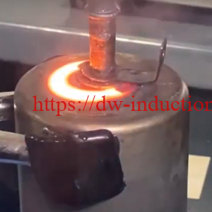
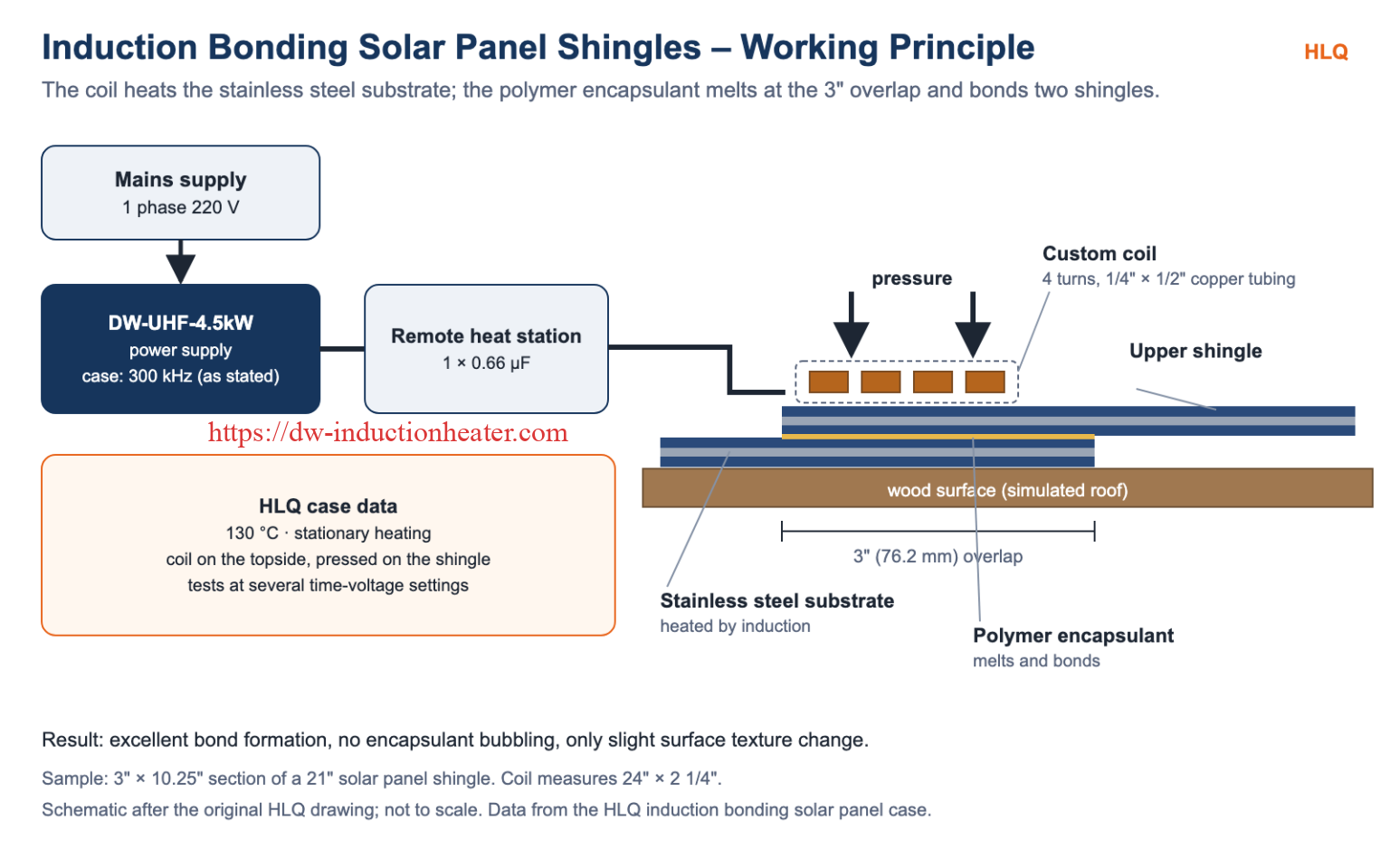
Induction bonding of solar panel shingles heats the stainless steel substrate of the shingle, and that heat melts the polymer encapsulant. The melted encapsulant bonds two overlapping shingles together. In the HLQ case, a 3″ × 10.25″ section of a 21″ solar panel shingle was bonded at a 3″ overlap at 130 °C. The equipment was a DW-UHF-4.5kW (300 kHz as stated) with a custom 4-turn coil of 1/4″ × 1/2″ rectangular copper tubing measuring 24″ × 2 1/4″. The water-cooled coil sat on the topside of the sample for stationary heating and was pressed against the shingle to apply bonding pressure. The tests gave excellent bond formation with no encapsulant bubbling and only a slight change in surface texture.
Table of Contents
- What is Induction Bonding of Solar Panels?
- Key Applications
- Suitable Materials
- Working Principle
- Technical Specifications
- Recommended Model Selection
- Process Workflow
- Common Problems and Solutions
- Engineering Selection Guide
- Advantages and Limitations
- Why Choose HLQ?
- 10 Core FAQs
What is Induction Bonding of Solar Panels?
Induction bonding of solar panels uses an induction coil to heat the metal substrate inside a solar panel shingle. The polymer encapsulant in contact with the hot substrate melts, so two overlapping shingles bond together. The polymer is not heated by the coil directly; only the stainless steel substrate is. The same principle is used in induction bonding plastic and other polymer-to-metal joints.

Key Applications
- Bonding overlapping solar panel shingles through their polymer encapsulant (this page).
- Soldering solar flex circuits: see soldering solar panels with induction.
- Rubber gaskets on steel assemblies: see induction bonding rubber to steel.
- Steel clips press-bonded into rubber seals: see bonding steel into rubber.
- Plastic reflow bonding of medical tubing: see induction heating plastic catheter tube.
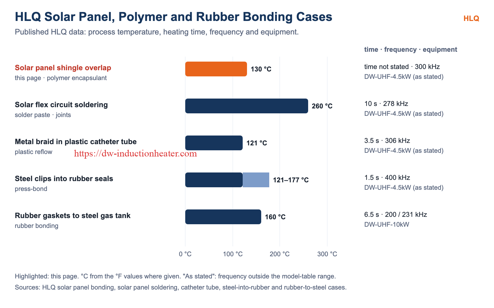
| HLQ case | Temperature | Time | Frequency | Equipment |
|---|---|---|---|---|
| Solar panel shingle overlap (this page) | 130 °C | Several time-voltage settings tested | 300 kHz (as stated) | DW-UHF-4.5kW |
| Solar flex circuit soldering | 500 °F (260 °C) | 10 s | 278 kHz (as stated) | DW-UHF-4.5kW |
| Metal braid in plastic catheter tube | 250 °F (121 °C) | 3.5 s | 306 kHz (as stated) | DW-UHF-4.5kW |
| Steel clips into rubber seals | 250–350 °F (121–177 °C) | 1.5 s | 400 kHz (as stated) | DW-UHF-4.5kW |
| Rubber gaskets to steel gas tank | 320 °F (160 °C) | 6.5 s | 200 / 231 kHz | DW-UHF-10kW |
Suitable Materials
| Metal part (heated) | Polymer / non-metal (bonded) | HLQ source |
|---|---|---|
| Stainless steel substrate of a solar panel shingle | Polymer encapsulant | This page |
| Wires on solar flex circuits | Solder Plus Paste 63NC-A (soldering) | Solar panel soldering case |
| Steel gas tank assembly | Rubber gaskets | Rubber-to-steel case |
| Metal braid | Plastic catheter tube | Catheter tube case |
Working Principle
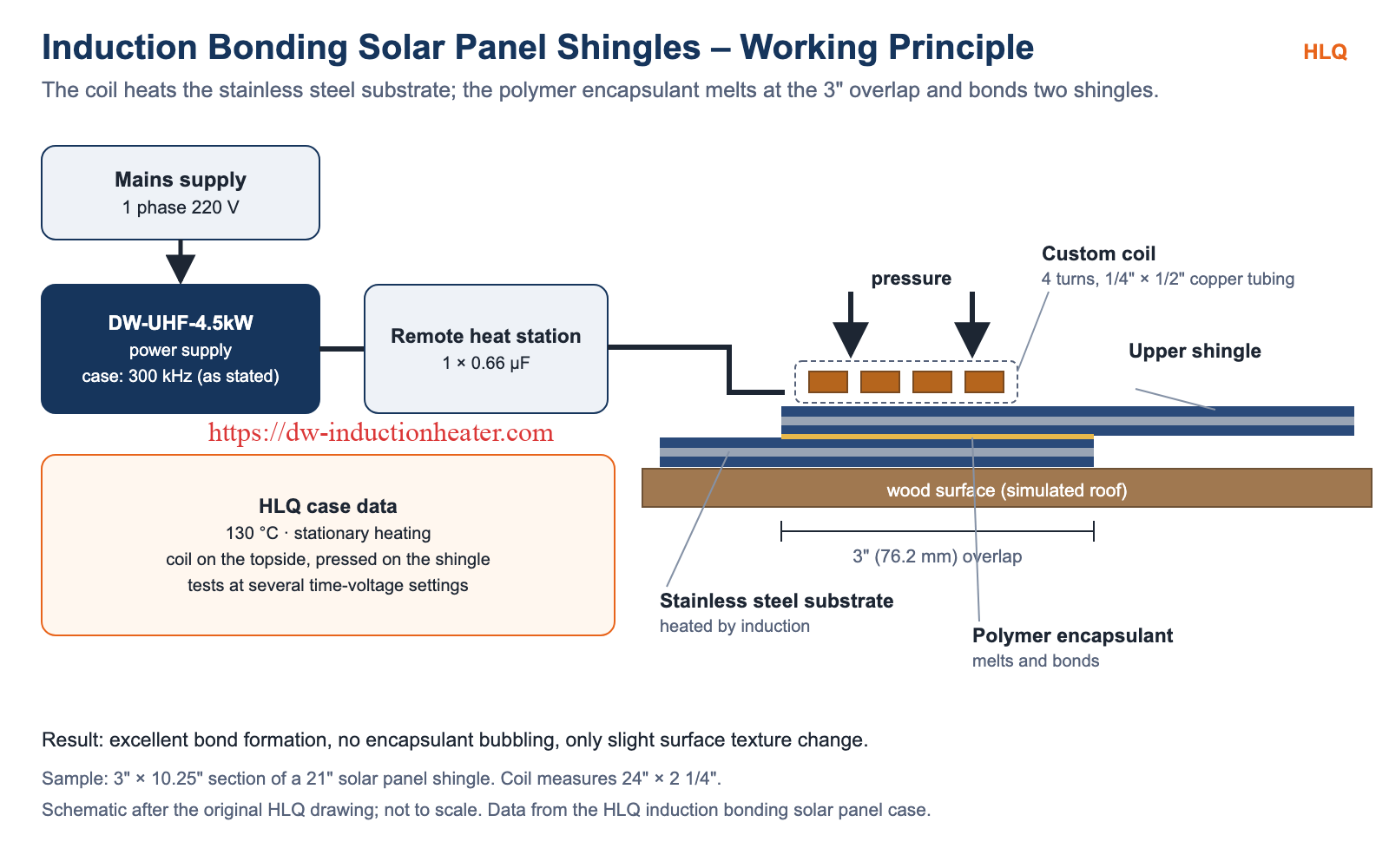
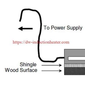
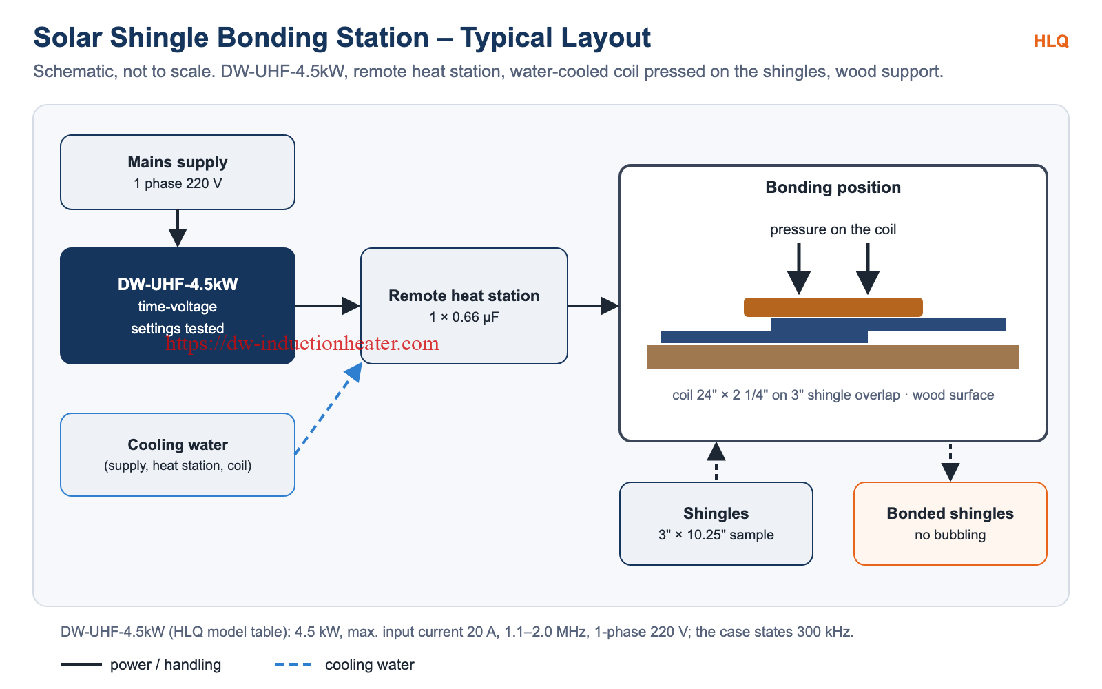
The DW-UHF-4.5kW feeds a remote heat station containing one 0.66 µF capacitor. The station drives a custom coil of 4 turns of 1/4″ × 1/2″ rectangular copper tubing, measuring 24″ × 2 1/4″. With the coil on the topside of the 3″ overlap, the stainless steel substrate is heated in place (stationary heating) until the polymer encapsulant melts at 130 °C. The water-cooled coil is pressed against the shingle at the same time, which helps the bond form. For coil options, see induction heating coil design.
Technical Specifications
| Parameter | HLQ case data |
|---|---|
| Objective | To heat the stainless steel substrate of a solar panel shingle in order to melt the polymer encapsulant, allowing two shingles to bond together with a 3″ (76.2 mm) overlap |
| Material | 3″ × 10.25″ (76.2 × 260.35 mm) section of a 21″ (533.4 mm) solar panel shingle |
| Temperature | 130 °C |
| Frequency | 300 kHz (as stated) |
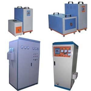
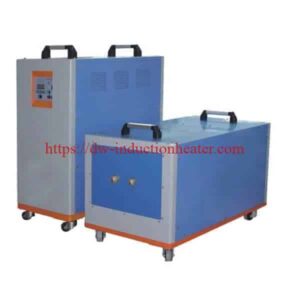
| Equipment | DW-UHF-4.5kW power supply with a remote heat station containing one 0.66 µF capacitor |
| Coil | Custom-made: 4 turns of 1/4″ × 1/2″ (6.35 × 12.7 mm) rectangular copper tubing, measuring 24″ × 2 1/4″ (609.6 × 57.15 mm) |
| Heating method | Stationary heating with the coil on the topside of the sample |
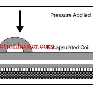
| Pressure | Applied by pressing the water-cooled coil against the shingle |
| Test settings | Several time-voltage settings |
| Results | Excellent bond formation with the absence of encapsulant bubbling and only slight surface texture change |
Recommended Model Selection
DW-UHF series data from the HLQ model table (100% duty cycle):
| Model | Power | Max. input current | Frequency | Supply | HLQ case |
|---|---|---|---|---|---|
| DW-UHF-4.5kW | 4.5 kW | 20 A | 1.1–2.0 MHz | 1-phase 220 V | Solar panel shingle (case states 300 kHz); solar flex circuits (case states 278 kHz) |
| DW-UHF-6.0kW | 6.0 kW | 28 A | 300–1100 kHz | 1-phase 220 V | – |
| DW-UHF-10kW | 10 kW | 15 A | 100–500 kHz | 3-phase 380 V | Rubber gaskets to steel gas tank |
Process Workflow
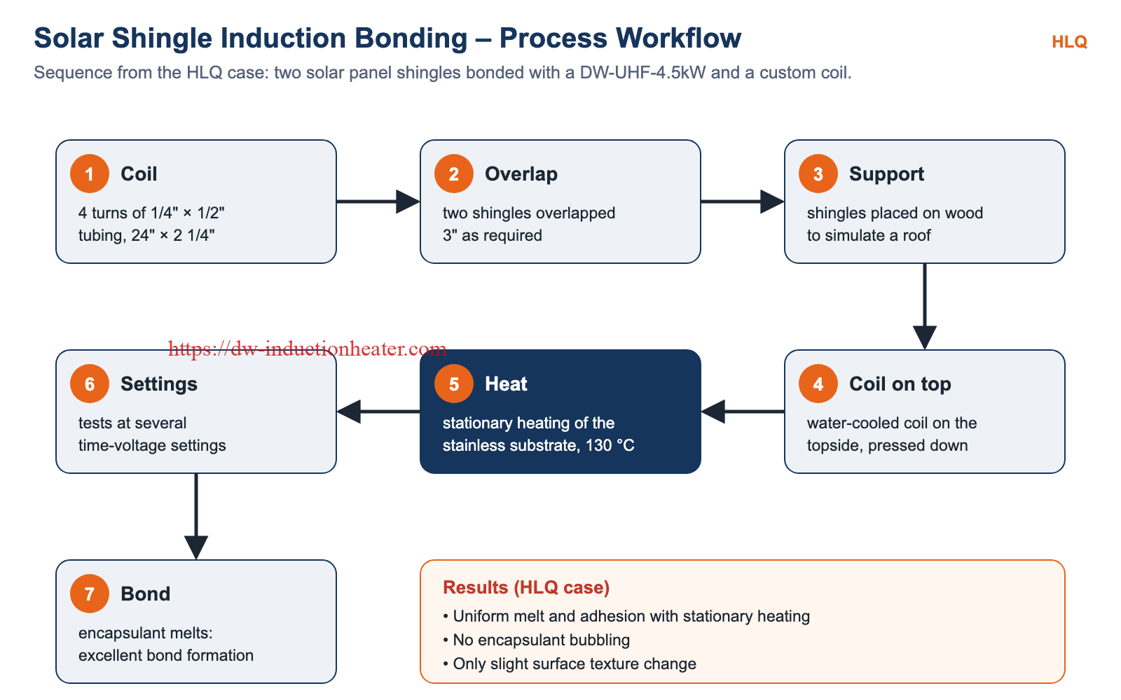
- Coil – a custom 4-turn coil of 1/4″ × 1/2″ rectangular copper tubing, 24″ × 2 1/4″.
- Overlap – the shingles are overlapped by 3″ according to requirements.
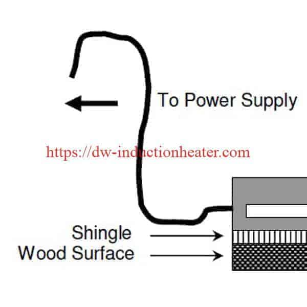
- Support – the shingles are placed on wood to simulate installation on a roofing surface.
- Coil on top – the water-cooled coil is placed on the topside of the sample and pressed against the shingle.
- Heat – stationary heating brings the stainless steel substrate to 130 °C.
- Settings – tests are performed at several time-voltage settings.
- Bond – the polymer encapsulant melts, giving uniform melt and adhesion.
Common Problems and Solutions
| Problem | Cause | Solution (HLQ data) |
|---|---|---|
| Non-uniform melt | Moving or uneven heating | Stationary heating with the coil on the topside of the sample |
| Weak adhesion | No contact pressure during melting | Pressure applied by pressing the water-cooled coil against the shingle |
| Encapsulant bubbling | Unsuitable heating settings | Tests at several time-voltage settings; no bubbling in the HLQ result |
| Surface damage | Excess heat | Only slight surface texture change at the tested settings |
| Results differ from field installation | Unrealistic test support | Shingles placed on wood to simulate a roofing surface |
Engineering Selection Guide
- Solar shingle overlap bonding: DW-UHF-4.5kW (single-phase 220 V) with a coil sized to the overlap, as in the HLQ case.
- Coil: a rectangular-tube coil matched to the overlap length (24″ × 2 1/4″ in the case) that can also apply pressure.
- Temperature: the melting temperature of the encapsulant (130 °C in the case).
- Settings: establish the time and voltage by testing on samples.
- Data to send: panel or shingle construction, substrate metal, encapsulant, overlap size, temperature and cycle time.
Advantages and Limitations
| Advantages | Limitations |
|---|---|
| Excellent bond formation | Requires a metal substrate in the shingle |
| No encapsulant bubbling | Time and voltage must be set by testing |
| Only slight surface texture change | The coil must be sized to the overlap |
| The water-cooled coil also applies the bonding pressure | Water cooling is required |
Why Choose HLQ?
- Published solar panel bonding and soldering data.
- Custom coils, including long rectangular-tube coils.
- Compact single-phase DW-UHF systems.
- Experience with polymer, rubber and plastic bonding to metal.
10 Core FAQs
1. What was bonded?
Two solar panel shingles, bonded together with a 3″ overlap.
2. What is heated by induction?
The stainless steel substrate of the shingle; its heat melts the polymer encapsulant.
3. What temperature is used?
130 °C.
4. What sample was tested?
A 3″ × 10.25″ section of a 21″ solar panel shingle.
5. Which equipment was used?
A DW-UHF-4.5kW power supply with a remote heat station containing one 0.66 µF capacitor, at 300 kHz as stated.
6. Which coil was used?
A custom-made coil of 4 turns of 1/4″ × 1/2″ rectangular copper tubing, measuring 24″ × 2 1/4″.
7. How is pressure applied?
The water-cooled coil is pressed against the shingle.
8. Why were the shingles placed on wood?
To simulate installation on a roofing surface.
9. What was the result?
Excellent bond formation, no encapsulant bubbling and only slight surface texture change.
10. What information is needed for a quotation?
Panel or shingle construction, substrate metal, encapsulant, overlap size, temperature and cycle time.