Iron Steel Scrap Melting Furnace
Iron Steel Scrap Melting Furnace and Induction Steel Smelting Furnace
The iron steel scrap melting furnace on this page is the HLQ GW series medium frequency induction furnace, supplied in EAF-equivalent sizes from 0.35 t to 30 t per heat and from 250 kW to 15,000 kW rated power. It remelts clean steel scrap, iron scrap, foundry returns, rejected castings and stainless scrap into a controlled molten bath for casting or alloy work. Every figure on this page is taken from HLQ’s own published GW series specification table, its published iron and steel melting pages and its published DW-MF crucible range. Nothing on this page is invented.
Scrap is a harder duty than virgin metal. Charge shape, charge density, matching power and operator proficiency all move the real melting time and kWh/T away from the catalogue band, and a wet, oily or sealed charge is a safety problem rather than an economic one. This page therefore treats the induction furnace for melting iron and steel as the engineering reference and concentrates on what changes when the charge is scrap.

Quick Answer
An iron and steel scrap melting furnace is a medium frequency induction furnace that melts ferrous scrap into molten metal by generating the heat inside the charge itself. The HLQ GW series runs from 0.35 t to 30 t EAF-equivalent capacity per heat and from 250 kW to 15,000 kW rated power at 0.25 kHz to 1 kHz. Heat is produced by eddy currents induced in the metal, so there is no flame, no electrode contact and no combustion gas touching the melt; the same rotating field stirs the bath so temperature and chemistry stay uniform across the heat. For a scrap duty the furnace is specified by batch weight, daily tonnage, charge condition and the incoming transformer capacity, not by the scrap tonnage alone. The published cast iron energy index falls from 560 kWh/T at GW-0.35T to 470 kWh/T at GW-20T and GW-30T, and the published melt cycle runs from 20-45 minutes at the small end to 50-90 minutes at the large end. For small batches, the DW-MF crucible range covers 15-160 kW with a steel and stainless melting ability of 4 kg to 100 kg.
Table of Contents
- Quick Answer
- Table of Contents
- What is the Iron Steel Scrap Melting Furnace?
- Key Applications
- Suitable Materials
- Working Principle
- Technical Specifications
- Recommended Model Selection
- Process Workflow
- Common Problems and Solutions
- Engineering Selection Guide
- Advantages and Limitations
- Why Choose HLQ?
- 6 Core FAQs
What is the Iron Steel Scrap Melting Furnace?
The iron steel scrap melting furnace is a coreless medium frequency induction furnace built for the specific job of turning ferrous scrap back into usable molten metal. In the trade the same machine is called an induction steel smelting furnace, a scrap melting induction furnace, a KGPS induction furnace or a steel shell induction furnace, depending on which part of the specification the buyer happens to be looking at.
What separates a scrap melting furnace from any other induction furnace is not the heating principle, which is identical, but the charge. A scrap charge is mixed grade, mixed shape, mixed temperature and often contaminated. The furnace therefore has to cope with bridging, uneven collapse, dirty charge, variable density and a constantly changing bath level. HLQ publishes this behaviour openly in the GW series note, which states that melting time and tons of power consumption have an important relationship with the equipment matching power, the raw material shape, the raw material density and worker proficiency. That single sentence is the most useful selection guide on this page.
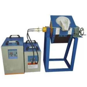
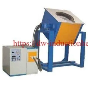
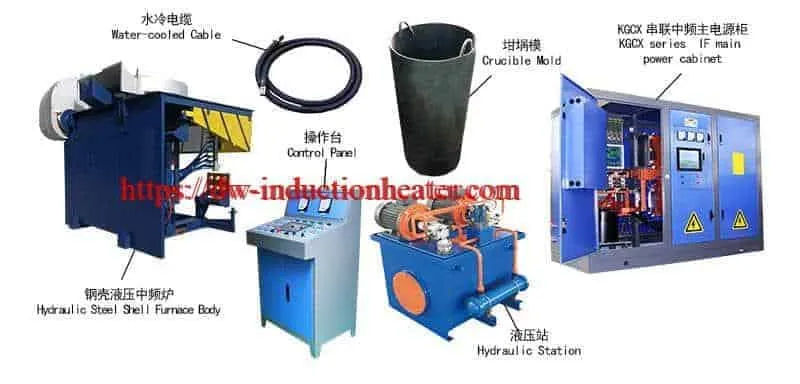
A complete scrap melting system contains eight working groups: the medium frequency power supply, the capacitor cabinet, the furnace body with its steel shell, the induction coil and refractory lining, the hydraulic tilting system, the water cooled cable, the cooling water circuit and the electrical control cabinet. For a scrap duty the published equipment configuration is listed as medium frequency power supply, capacitor cabinet, furnace body (steel shell or aluminum shell), hydraulic station (or reducer) tilting system and water cooling cable. Because the scrap duty is defined by tonnage rather than by a single workpiece, the furnace is usually the largest single item in the plant and the power supply is normally installed in a separate hall.
For buyers comparing this route with a gas or oil furnace, the practical difference is that the induction furnace has no combustion step at all. HLQ’s published feature text for this equipment claims a power factor of 0.96 or above at all times, a single furnace melting time as fast as under 40 minutes, and roughly 20 % energy saving against a common parallel inverter power supply. It also claims that because there is no flame contact there is less burning loss, so the metal yield from a scrap charge is higher than in a fuel-fired furnace.

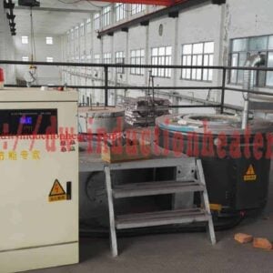
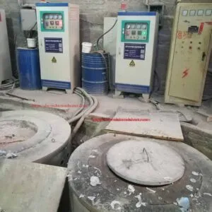
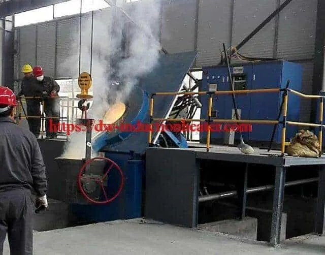
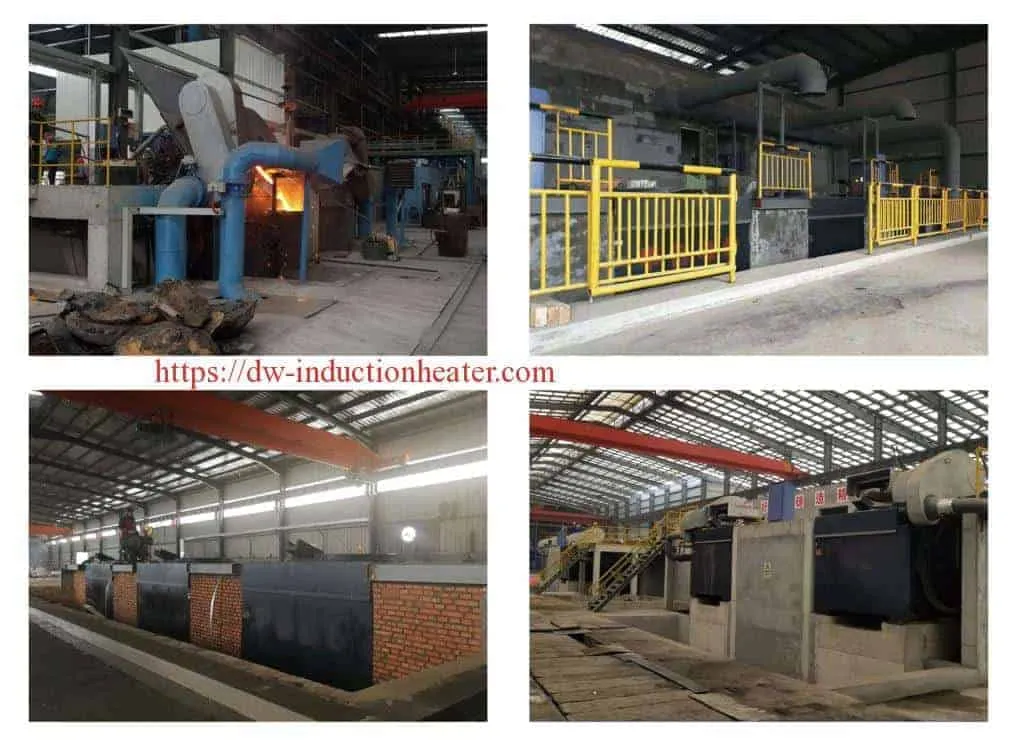
The two photographs below show the machine type in service. The first is a scrap melting furnace body with its cover open for charging, the second is an induction furnace running with fume extraction over the charge.
Related HLQ product pages cover the neighbouring duties in the same product family, including the induction melting furnace for general industrial melting, the aluminum melting furnace for non-ferrous work, the tilting melting gold furnace with induction, the aluminum scrap melting furnace and the high frequency heating furnace for heating rather than melting.
Key Applications
The scrap melting furnace is used wherever ferrous material comes back into the shop in a form that has to become molten metal again. The table below maps the published scrap duties to the furnace configuration HLQ recommends and to the outcome the buyer is buying.
| Scrap duty | Typical charge material | Recommended furnace configuration | Outcome for the buyer |
|---|---|---|---|
| Carbon steel remelt | Clean steel scrap, carbon steel, low-alloy steel | Steel shell induction furnace with hydraulic tilting | Fast melting and good temperature control for steel casting. |
| Cast iron remelt | Iron scrap, pig iron, foundry returns | Medium frequency induction furnace with a suitable iron lining | Stable molten iron supply for casting production. |
| Alloy steel remelt | Cr-Mo steel, Mn steel, tool steel, wear-resistant alloy | Temperature-controlled induction furnace | Improves alloy composition uniformity and repeatability. |
| Stainless remelt | 304, 316, stainless scrap, stainless alloy | Medium frequency induction furnace with controlled slag practice | Supports stainless casting and alloy recycling. |
| General scrap recycling | Clean steel scrap, iron scrap, rejected castings | Hydraulic tilting induction melting furnace | Converts scrap into reusable molten metal. |
| Foundry casting | Molten iron or steel for molds | Steel shell furnace with ladle pouring layout | Improves casting quality and production flexibility. |
| Small batch alloy development | Experimental steel or iron alloy | Small or medium induction crucible furnace | Flexible melting for trials and specialty production. |
Three further application points are worth separating out because they change the specification rather than the order code.
Scrap recycling with frequent batch changes. When the charge mix changes several times a day the limiting factor is charge handling, not melting energy. HLQ’s published selection logic recommends a medium frequency tilting furnace for this duty because the fast melting and flexible charge handling matter more than a very low kWh/T figure.
Stainless scrap. Stainless remelting needs its own discipline. HLQ publishes induction melting stainless steel at approximately 1,400-1,550 °C with a neutral or basic refractory lining, and states that oxidation and chromium loss are controlled with correct slag practice, temperature control and short holding times. A carbon steel furnace configured for mild steel scrap will not hold chrome back on the same terms.
Foundry iron supply. Where the output is iron rather than steel, the cast iron metallurgy takes over as the deciding factor. HLQ’s cast iron melting furnace page covers the gray and ductile iron melting ranges and the carbon equivalent controls that a scrap remelt must respect if the returned material is to be reused.
The wider industrial context for this equipment, including how the GW series compares with an electric arc furnace on capacity and energy, is covered on the iron steel smelter with induction page.
Suitable Materials
An induction furnace can melt any electrically conductive metal, but for iron and steel the furnace has to be designed for high temperature, high power density and a refractory lining matched to the metal and to the slag chemistry. HLQ publishes the following suitability ranges for ferrous materials.
| Material | Melting suitability | Typical melting temperature range | Engineering note |
|---|---|---|---|
| Gray cast iron | Excellent | Approximately 1150-1400 °C depending on composition | Very common foundry application; charge mix and carbon equivalent should be controlled. |
| Ductile iron | Excellent | Approximately 1300-1500 °C | Requires good base iron quality before nodularizing treatment. |
| Carbon steel | Excellent | Approximately 1450-1600 °C | Requires high temperature lining and sufficient power capacity. |
| Low-alloy steel | Excellent | Approximately 1450-1650 °C | Alloy loss and final chemistry should be monitored. |
| Stainless steel | Good | Approximately 1400-1550 °C | Oxidation and chromium loss should be controlled with correct slag practice. |
| High-manganese steel | Good | Approximately 1400-1500 °C | Suitable for wear-resistant casting, but lining compatibility matters. |
| Tool steel | Good | Approximately 1450-1600 °C | Requires accurate temperature control and alloy management. |
| Scrap iron and steel | Good if clean and dry | Depends on composition | Moisture, sealed cavities, oil and contamination must be removed before charging. |
Alongside these melting ranges, the GW series publishes the working in-furnace temperature set for each metal on the scrap furnace. These are the furnace temperatures, not the melting ranges above.
| Metal | Published in-furnace temperature | Metal | Published in-furnace temperature |
|---|---|---|---|
| Steel | 1650 °C | Brass | 1000 °C |
| Cast iron | 1450 °C | Aluminum | 700 °C |
| Red copper | 1150 °C | Zinc | 400 °C |
Because the GW series is a ferrous furnace, the non-ferrous metals above are only reachable with the correct lining and at a different power match. If the plant also runs aluminum, HLQ’s dedicated aluminum melting furnace range is the matched route rather than adapting the scrap furnace.
For scrap specifically, the material question is not only the grade but the physical state of the charge. HLQ’s published limitation list states plainly that moisture can expand rapidly and cause molten metal splashing, and that dry clean charge materials with no sealed scrap pieces are the requirement.
| Charge condition | Published requirement before charging | Why it matters on a scrap duty |
|---|---|---|
| Moisture | Must be removed | Moisture expands rapidly and can throw molten metal out of the furnace. |
| Sealed cavities | Sealed containers must be removed | Trapped gas or liquid behaves like the moisture case and causes splashing on charging. |
| Oil and contamination | Must be removed | Oil on the charge is the most common cause of molten metal splashing during charging. |
| Charge shape | Properly sized charge | Published note: melting time and tons of power consumption depend on the raw material shape. |
| Charge density | Known and consistent | Published note: melting time and tons of power consumption depend on the raw material density. |
| Operator proficiency | Trained charging discipline | Published note: worker proficiency is listed alongside power and material as a driver of the real result. |
Working Principle
The working principle of an iron and steel scrap melting furnace is electromagnetic induction. The medium frequency power supply converts factory AC electricity into furnace current. That current flows through a water-cooled copper induction coil built around the crucible and the refractory lining. The coil generates an alternating magnetic field which penetrates the iron or steel charge inside the furnace.
Because iron and steel are conductive, the changing magnetic field induces circulating currents inside the metal charge. These circulating currents are eddy currents. When they flow through the electrical resistance of the metal they generate heat, and the charge softens, collapses and melts into a molten bath. Once the bath exists, the electromagnetic force creates a natural stirring action. That stirring distributes heat and alloying elements evenly, which for a scrap remelt is the whole point: a mixed charge would otherwise stratify, and a mixed charge that stratifies produces a casting with inconsistent chemistry.
There is no combustion in this process. Nothing is burned and no electrode touches the metal. HLQ’s published feature text for this equipment lists a zero-voltage sweep-frequency start that adapts to frequent starting, and a protection set covering over-current, over-voltage, current limiting, voltage limiting, water-break and default protection, with the equipment running reliably under the condition that melting speed is guaranteed.
Three published component details matter on a scrap duty. First, the coil: HLQ states that the induction coil loss of a medium frequency furnace accounts for 25 % of the total power, so the coil is designed with high quality TU1 oxygen-free copper in aluminum copper and high silver brazing at the coil joint, with insulation material implanted between turns to improve the insulation level and obtain the maximum electric thermal efficiency. Second, the power supply: using a full-wave rectifier power supply series, the rectifier stays in a state of full open during the whole working process, equivalent to a diode rectifier, so it does not produce higher harmonics, which means basic no pollution to the power network and no effect on the operation of the substation reactive power compensation capacitor. Third, the furnace cover: the equipment uses a whirlwind and side suction heat preservation furnace cover and a dust hood with ring air absorption to collect the waste gas generated in smelting, improve exhaust emission effect and meet the requirements of environmental impact assessment design.
For a scrap duty the working principle also explains why the scrap itself is the hard part. The eddy current is generated in the metal, so the metal must be electrically continuous and in good contact with itself. A loose pile of thin sheet, a bundle of long bar or a bucket of turnings behaves very differently from a solid bottom charge, and this is why the charging sequence in the process workflow below starts with a carefully placed bottom charge.
| Step | Process | What happens in the furnace |
|---|---|---|
| 1 | Power input | Three-phase factory power enters the induction furnace power supply. |
| 2 | Frequency conversion | The power supply converts input power into medium frequency furnace current. |
| 3 | Coil excitation | Current flows through the water-cooled copper induction coil. |
| 4 | Magnetic field formation | The coil generates an alternating magnetic field around the crucible. |
| 5 | Eddy current heating | Eddy currents are induced inside the iron or steel charge. |
| 6 | Joule heat generation | Electrical resistance converts the induced current into heat. |
| 7 | Melting | The solid charge melts into a molten iron or steel bath. |
| 8 | Electromagnetic stirring | The molten metal circulates, helping temperature and composition uniformity. |
| 9 | Tilting and pouring | The hydraulic system tilts the furnace to pour molten metal into ladles or molds. |

Technical Specifications
The GW series specification below is HLQ’s own published table. It is reproduced with the columns in their correct published order. The original published table has no separate model column heading, so the model designation is given first here; the EAF-equivalent capacity of each model is encoded in its designation, GW-0.35T being 0.35 t EAF-equivalent capacity and GW-30T being 30 t.
GW series power supply and incoming line parameters
| Type | Rated power (kW) | Incoming voltage (V) | Incoming line current (A) | Rectifying pulse number | Rectifier transformer capacity (kVA) |
|---|---|---|---|---|---|
| GW-0.35T | 250 | 380 | 400 | 6 | Three-phase 315 |
| GW-0.5T | 350 | 380 | 560 | 6 | Three-phase 400 |
| GW-0.75T | 500 | 380 | 800 | 6 | Three-phase 630 |
| GW-1T | 800 | 380 / 750 | 1,280 / 656 | 6 / 6 | Three-phase 1,000 / Three-phase 1,000 |
| GW-1.5T | 1,000 | 380 / 750 | 800 / 820 | 12 / 6 | Double three-phase 1,250 / Three-phase 1,250 |
| GW-2T | 1,400 | 750 / 750 | 1,148 / 574 | 6 / 12 | Three-phase 1,800 / Double three-phase 1,800 |
| GW-3T | 2,000 | 750 | 820 | 12 | Double three-phase 2,500 |
| GW-5T | 3,000 | 950 | 1,140 | 12 | Double three-phase 4,000 |
| GW-10T | 6,000 | 950 | 2,280 | 12 | Double three-phase 8,000 |
| GW-15T | 8,000 | 950 | 1,520 | 24 | Four three-phase 10,000 |
| GW-20T | 10,000 | 950 | 1,900 | 24 | Four three-phase 12,500 |
| GW-30T | 15,000 | 950 | 2,850 | 24 | Four three-phase 20,000 |
GW-1T, GW-1.5T and GW-2T are published with two operating taps. The values are given as published, first tap then second tap. GW-1.5T for example offers a reduced tap delivering roughly half power at 380 V and a full tap at 750 V, and GW-2T offers a full 1,400 kW tap and a reduced 700 kW tap on the same 750 V incoming supply. This is what allows one furnace to cover two different scrap grades or two different production rates without buying a second furnace.
GW series DC link, medium frequency output and melt cycle
| Type | DC voltage (V) | Direct current (A) | Medium frequency voltage (V) | Intermediate frequency (kHz) | Melting time (min) |
|---|---|---|---|---|---|
| GW-0.35T | 500 | 500 | 750 | 1 | 20-45 |
| GW-0.5T | 500 | 700 | 750 | 0.8 | 30-50 |
| GW-0.75T | 500 | 1,000 | 750 | 0.8 | 40-50 |
| GW-1T | 500 / 990 | 1,600 / 808 | 750 / 1,480 | 0.7 | 40-50 |
| GW-1.5T | 500 / 990 | 1,000 / 1,010 | 750 / 1,480 | 0.7 | 40-60 |
| GW-2T | 990 / 990 | 1,414 / 707 | 1,480 / 1,480 | 0.5 | 45-60 |
| GW-3T | 990 | 1,010 | 1,480 | 0.5 | 50-70 |
| GW-5T | 1,260 | 1,190 | 1,900 | 0.3 | 50-80 |
| GW-10T | 1,260 | 2,380 | 1,900 | 0.3 | 50-90 |
| GW-15T | 1,260 | 1,590 | 1,900 | 0.3 | 50-90 |
| GW-20T | 1,260 | 1,980 | 1,900 | 0.25 | 50-90 |
| GW-30T | 1,260 | 2,980 | 1,900 | 0.25 | 50-90 |
Note the frequency ladder. The GW series drops from 1 kHz at 0.35 t to 0.25 kHz at 20 t and 30 t, because a larger bath needs a deeper magnetic penetration to move heat into the centre of the charge. For a scrap duty with a heavy, cold charge this is the parameter that decides how long the centre of the bath takes to come up to temperature.
GW series published energy index
| Type | Cast iron (kWh/T) | Red copper (kWh/T) | Brass (kWh/T) | Aluminum (kWh/T) |
|---|---|---|---|---|
| GW-0.35T | 560 | 420 | 390 | 540 |
| GW-0.5T | 550 | 410 | 380 | 530 |
| GW-0.75T | 550 | 410 | 380 | 530 |
| GW-1T | 540 | 400 | 370 | 520 |
| GW-1.5T | 530 | 390 | 360 | 510 |
| GW-2T | 520 | 380 | 350 | 500 |
| GW-3T | 510 | 370 | 340 | 490 |
| GW-5T | 500 | 360 | 330 | 480 |
| GW-10T | 490 | 350 | 320 | 470 |
| GW-15T | 480 | 340 | 310 | 460 |
| GW-20T | 470 | 330 | 300 | 450 |
| GW-30T | 470 | 330 | 300 | 450 |
HLQ’s published note on this column is important and is often left out of quotations. It states that the ton power consumption (kWh/T) figures above describe this new series of power consumption, which will consume 15 % or more of the power supply in a common parallel induction furnace power supply at the same tonnage. In other words, this is a dedicated series efficiency figure and not a comparison against the best available induction supply. The published feature text for the same equipment quotes an extremely competitive energy consumption index of about 530 kWh/T for cast iron and about 20 % energy saving compared with a common parallel inverter power supply.
Published GW series notes
- The capacity of the iron and steel scrap melting furnace is based on the density of steel 7.8. The density of aluminum is 2.7, so aluminum of equal weight uses the same matching power and needs a furnace body three times the size.
- The melting time and tons of power consumption have an important relationship with the equipment matching power, the raw material shape, the raw material density and worker proficiency.
- The ton power consumption (kWh/T) is a new series of power consumption which will consume 15 % or more of the power supply than a common parallel induction furnace power supply.
- Equipment configuration: medium frequency power supply, capacitor cabinet, furnace body (steel shell or aluminum shell), hydraulic station (or reducer) tilting system, water cooling cable and so on.
- The above is the standard product data. Different power can be designed according to user demand, and non-standard products with different melting speeds can be supplied.
Small capacity route: the DW-MF crucible range
Where the batch is a crucible load rather than a foundry heat, HLQ publishes the DW-MF series as the matched route. It runs on 3 x 380 V plus or minus 20 %, 50 or 60 Hz, with a generator input voltage of 70-550 V, an oscillate frequency of 1 kHz to 20 kHz normally about 4, 8, 11, 15 or 20 kHz according to the application, and a 100 % duty cycle for 24 hours work. The system has three main parts: the medium frequency induction heating generator, the melting furnace and the compensation capacitor.
| Model | Max input power | Steel and stainless steel | Gold and silver | Aluminum | Weight |
|---|---|---|---|---|---|
| DW-MF-15 | 15 kW | Not published | 5 kg or 10 kg | 3 kg | 50 kg |
| DW-MF-25 | 25 kW | 4 kg or 8 kg | 10 kg or 20 kg | 6 kg | 50 kg |
| DW-MF-35 | 35 kW | 10 kg or 14 kg | 20 kg or 30 kg | 12 kg | 65 kg |
| DW-MF-45 | 45 kW | 18 kg or 22 kg | 40 kg or 50 kg | 21 kg | 70 kg |
| DW-MF-70 | 70 kW | 28 kg | 60 kg or 80 kg | 30 kg | 80 kg |
| DW-MF-90 | 90 kW | 50 kg | 80 kg or 100 kg | 40 kg | 94 kg |
| DW-MF-110 | 110 kW | 75 kg | 100 kg or 150 kg | 50 kg | 114 kg |
| DW-MF-160 | 160 kW | 100 kg | 150 kg or 250 kg | 75 kg | 145 kg |
HLQ publishes the DW-MF melt cycle as about 30-50 minutes with the first cold melt, and adds about 20-30 minutes for the later melt when the furnace is already hot. The steel and stainless figures for DW-MF-25 through DW-MF-45 are published as two capacities, which correspond to the two power taps available on those models.
Control, safety and cooling
| Item | Published specification |
|---|---|
| Power supply type | Medium frequency, full-wave rectifier power supply series with IGBT inverter and digital phase locked loop frequency tracking. |
| Power control | Constant power output; automatic load impedance matching; closed-loop power control. |
| Start method | Zero-voltage sweep-frequency start, adapts to the requirement of frequently starting. |
| Power factor | 0.96 and above throughout the working cycle. |
| Protection | Over-current, over-voltage, current limiting, voltage limiting, water-break and default protection. |
| Harmonics | Full-wave rectifier power supply series; the rectifier stays fully open during the whole working process, so no higher harmonics are produced, giving basic no pollution to the power network and no effect on the substation reactive power compensation capacitor. |
| Cooling | Water cooling for the coil, power supply, capacitor cabinet and water-cooled cables; plate heat exchange system to keep cooling water temperature controlled and to prevent external hard water entering the power supply. |
| Component build | Imported high pressure carbon-free hose with 304 stainless steel clamp; optical fiber transmission inverter trigger pulse signal plate; heavy platform thyristor with square type water cooling radiator; customized horizontal capacitor with magnesium aluminum alloy shell; large thick conductive copper bar, sandblasted and anti-oxidation coated; isolation (exchange) switch so one furnace can be de-energized without affecting another. |
| Furnace structure | Steel shell furnace structure with hydraulic tilting. |
| Coil | High quality TU1 oxygen-free copper in aluminum copper with high silver brazing at the joint and insulation material between turns. |
| Environmental | Whirlwind and side suction heat preservation furnace cover, with a dust hood and ring air absorption to collect smelting waste gas and improve exhaust emissions. |
Recommended Model Selection
The table below is HLQ’s published model selection guide. It is expressed in production terms, which is the correct frame for a scrap duty because the scrap tonnage, not the metal grade, sets the equipment.
| Application | Material | Recommended power | Frequency |
|---|---|---|---|
| Small cast iron melting | Gray iron, pig iron, return scrap | 100 kW – 250 kW | Medium frequency, typically 0.5-2.5 kHz depending on furnace size |
| Small steel casting workshop | Carbon steel, low-alloy steel | 160 kW – 350 kW | Medium frequency / KGPS |
| 500 kg cast iron melting | Cast iron, pig iron, foundry returns | 250 kW – 500 kW | Medium frequency |
| 1 ton iron or steel melting | Cast iron, carbon steel, alloy steel | 500 kW – 800 kW | Medium frequency / KGPS |
| 2 ton foundry melting | Iron, carbon steel, alloy steel | 1,000 kW – 1,500 kW | Medium frequency |
| 3 ton heavy-duty steel melting | Steel scrap, alloy steel, stainless steel | 1,500 kW – 2,000 kW | Medium frequency, lower range for larger bath |
| 5 ton industrial foundry melting | Cast iron, steel, heavy scrap | 2,000 kW – 2,500 kW and above | Medium frequency / high-power furnace system |
| Stainless steel melting | Stainless scrap and stainless alloy | Depends on batch size, typically 500 kW – 2,500 kW | Medium frequency with accurate temperature control |
Mapping this onto the GW series published table gives a direct model choice. A foundry melting 500 kg of cast iron a heat runs GW-0.35T to GW-0.75T at 250 kW to 500 kW. A one ton steel casting shop runs GW-1T at 800 kW. A two ton foundry runs GW-1.5T or GW-2T at 1,000 kW or 1,400 kW. A three ton heavy-duty steel scrap line runs GW-3T at 2,000 kW, and an industrial foundry working 5 t heats runs GW-5T and above. Where the plant also needs stainless, HLQ’s electric steel melting furnace and medium frequency steel melting furnace pages carry the detailed capacity and frequency ladder for the same hardware.
Furnace capacity selection reference
| Furnace capacity | Typical use | Recommended furnace body | Engineering comment |
|---|---|---|---|
| 10-100 kg | Laboratory, trial melting, small castings | Small crucible furnace | Good for samples and specialty alloys. |
| 150-350 kg | Small foundry, repair casting, small batch production | Aluminum shell or compact steel shell | Lower investment and flexible operation. |
| 500-1000 kg | Medium foundry production | Hydraulic tilting steel shell furnace | Common choice for continuous casting workshops. |
| 1500-3000 kg | Large foundry and steel casting | Steel shell furnace | Requires strong transformer, cooling and safety system. |
| 3000-5000 kg | Heavy industrial melting | Heavy-duty steel shell furnace | Designed for high output and long production shifts. |

Process Workflow
A safe and efficient scrap remelt requires more than turning on the power. Operators must prepare the charge correctly, inspect the lining, confirm cooling water, follow a proper melting curve and control the pouring temperature. HLQ publishes a twelve-step foundry melting sequence, which applied to a scrap remelting duty reads as follows.
| Step | Operation | Key control point |
|---|---|---|
| 1 | System inspection | Check power cabinet, cooling water, hydraulic system, grounding and alarms. |
| 2 | Lining inspection | Confirm refractory lining thickness, cracks, erosion and sintering condition. |
| 3 | Charge preparation | Use dry, clean and properly sized iron or steel charge. Avoid sealed or wet scrap. |
| 4 | Initial charging | Place suitable bottom charge carefully to protect the furnace lining. |
| 5 | Power start | Start at appropriate power level and increase as charge condition becomes stable. |
| 6 | Main melting | Monitor voltage, current, water pressure, furnace noise and melting progress. |
| 7 | Additional charging | Add remaining scrap gradually after molten pool formation; avoid bridging. |
| 8 | Alloying and chemistry adjustment | Add carbon, silicon, manganese, chromium or other alloying materials as required. |
| 9 | Slag removal | Remove slag to improve molten metal cleanliness. |
| 10 | Temperature measurement | Confirm pouring temperature using suitable measurement equipment. |
| 11 | Tilting and pouring | Use hydraulic tilting to pour molten metal into ladle or mold safely. |
| 12 | Post-melting check | Inspect lining, record energy consumption, melting time and production data. |
Steps 3, 4 and 7 are where a scrap duty differs from a foundry duty, and they should be treated as a single discipline rather than three separate instructions. Charge preparation means grading by grade and by shape, removing oil and moisture, and removing anything with a sealed cavity. Initial charging means placing a dense bottom charge against the lining so that the first impact and the first heat do not go into the refractory. Additional charging means adding the remaining scrap in stages after a molten pool exists, because dropped bulk scrap bridges and then collapses suddenly, which splashes molten metal and can damage the lining.
The published workshop flow chart condenses the same sequence into five phases: charge preparation, melting, refining and adjustment, pouring, and production record. The production record phase is the one most often skipped and the one that pays back, because it is the record of energy, time, lining condition and casting quality that tells you whether the next heat should run at the same power or at a different tap.

Common Problems and Solutions
Most induction furnace problems on a scrap duty come from incorrect power selection, poor charge preparation, weak cooling, unsuitable lining, unstable electrical supply or poor operating practice. The table below is HLQ’s published troubleshooting reference, which applies directly to a scrap remelt.
| Problem | Possible cause | Engineering solution |
|---|---|---|
| Melting time is too long | Power is too low, charge is too large, voltage is unstable or lining insulation is poor. | Select higher power, improve charge size, inspect lining and confirm transformer capacity. |
| Power consumption is too high | Long holding time, wet charge, excessive superheating or poor lining condition. | Reduce holding time, dry charge, optimize temperature target and maintain lining. |
| Furnace alarms frequently | Cooling water problem, over-current, over-voltage, load mismatch or capacitor fault. | Check water pressure, water flow, capacitor cabinet, input voltage and furnace load. |
| Molten bath temperature is uneven | Poor charge distribution, insufficient melting time or weak stirring. | Improve charging sequence and allow complete melting before temperature measurement. |
| Furnace lining wears quickly | Wrong refractory material, poor sintering, thermal shock or mechanical damage during charging. | Use correct lining material, follow sintering procedure and avoid heavy impact loading. |
| Molten metal splashes during charging | Wet scrap, sealed cavities, oil contamination or improper charging. | Use dry clean scrap, remove sealed containers and charge carefully. |
| Oxidation or alloy loss is high | Overheating, long holding time, poor slag practice or incorrect alloy addition sequence. | Control temperature, shorten holding time and optimize alloy and slag practice. |
| Pouring is unstable | Hydraulic system issue, poor ladle position or worn tilting structure. | Inspect hydraulic cylinder, hinge, limit switch and pouring layout. |
On a scrap duty the fourth and sixth rows of that table are the two that account for most production downtime, and they have a common cause. Both are charging problems rather than furnace problems. A charge that arrives wet, oily or full of sealed pieces cannot be made safe by any setting on the power supply.
Engineering Selection Guide
Selecting an iron and steel scrap melting furnace should not be based on furnace capacity alone. Two furnaces with the same nominal capacity can have very different melting speeds, energy consumption and safety performance depending on the power rating, the furnace shell design, the lining material, the transformer capacity and the cooling system. For a scrap duty the charge is variable, so the selection work should start from the production data and work backwards to the equipment.
| Selection factor | What to confirm | Engineering recommendation |
|---|---|---|
| Metal type | Cast iron, carbon steel, stainless steel or alloy steel. | Select lining chemistry and power density according to metal type. |
| Batch capacity | Required kilograms or tons per melt. | Select furnace capacity with practical loading and pouring margin. |
| Target melting time | Required minutes per batch. | Higher power shortens melting time but requires stronger electrical infrastructure. |
| Daily production | Tons per shift or tons per day. | Determine whether one furnace is enough or multiple furnaces are needed. |
| Input power supply | Factory voltage, transformer capacity and cable size. | Confirm electrical room capacity before ordering a high-power furnace. |
| Furnace body | Steel shell or aluminum shell. | Use steel shell for larger iron and steel melting or heavy-duty foundry operation. |
| Tilting system | Manual, mechanical or hydraulic tilting. | Hydraulic tilting is recommended for medium and large furnaces. |
| Cooling system | Water flow, pressure, temperature and water quality. | Use a closed-loop cooling tower or industrial chiller according to local conditions. |
| Safety protection | Leak furnace alarm, water pressure protection, emergency stop and over-current protection. | Do not reduce safety configuration for steel and iron melting projects. |
| Workshop layout | Charging area, crane, ladle path, mold area and cooling equipment position. | Plan furnace layout before finalizing equipment dimensions. |
Four scrap-specific checks are added to that published list.
Charge specification. Ask the supplier to see a graded, dried charge, not a nominal grade list. The published suitability entry for scrap iron and steel reads “good if clean and dry”, and that condition has to be met by the plant, not by the furnace.
Density and power match. Because the capacity of this furnace is based on the density of steel at 7.8, a charge that is mostly light-gauge sheet or structural section will behave differently from a charge of solid bar. The published note is that at equal weight the matching power is the same but the furnace body needs three times the volume for aluminum at density 2.7. The same logic applies to low-density scrap within the ferrous range.
Duty cycle and start frequency. The zero-voltage sweep-frequency start is published as adapting to the requirement of frequently starting. For a plant that runs a heat every two hours this is worth confirming in the quotation, and for a plant running continuous shifts it is what allows the 100 % duty cycle rating to be relied on.
Pour and layout, not just power. A 30 t furnace that cannot get a ladle under the tilt nose, or a charging bay that puts the crane in the furnace hall traffic lane, will underperform its published kWh/T no matter how well the power supply is matched. Plan the charging area, crane path, ladle route and mold area before the equipment dimensions are frozen.
For a plant that also produces a small quantity of specialty alloy or runs trials, HLQ’s published practical selection logic sets out four clear bands.
| Buyer requirement | Recommended choice | Reason |
|---|---|---|
| Small batch cast iron melting | 100-350 kg induction furnace | Flexible operation and lower investment. |
| Medium foundry production | 500 kg – 1 ton hydraulic tilting furnace | Balanced capacity, power and pouring convenience. |
| Large steel casting | 2-5 ton steel shell induction furnace | Strong structure and suitable for high-temperature heavy-duty melting. |
| Scrap recycling with frequent batch changes | Medium frequency tilting furnace | Fast melting and flexible charge handling. |
| High-alloy steel production | Temperature-controlled furnace with good slag practice | Better control of alloy composition and molten metal quality. |
Advantages and Limitations
Advantages
| Advantage | Engineering meaning | Buyer value |
|---|---|---|
| Fast melting | Heat is generated directly inside the iron or steel charge. | Shorter melting cycle and higher production output. |
| Clean electric heating | No combustion flame inside the furnace. | Cleaner workshop environment than many fuel-fired systems. |
| Good temperature control | Electrical power can be adjusted quickly. | More stable pouring temperature and casting quality. |
| Electromagnetic stirring | Molten metal circulates naturally under magnetic force. | Improves bath temperature uniformity and alloy mixing, which matters more on a mixed scrap charge. |
| Lower oxidation loss | Reduced flame contact and controlled melting atmosphere. | Improves metal yield and reduces material waste on every heat. |
| Flexible raw material use | Can melt pig iron, return scrap, steel scrap and alloy additions. | Useful for foundries and recycling plants. |
| Automation compatibility | Can be integrated with PLC, HMI and temperature feedback. | Supports intelligent production and operation traceability. |
| Controlled pouring | Hydraulic tilting enables stable molten metal discharge. | Improves safety and casting workflow. |
| Published energy index | Cast iron energy index of 470-560 kWh/T across the GW series, falling as furnace size rises. | A measurable operating cost for the buyer to plan against. |
Limitations
| Limitation | Reason | Recommended solution |
|---|---|---|
| High electrical demand | Melting iron and steel requires large electrical power. | Confirm transformer capacity, input voltage and cable size before installation. |
| Cooling water is essential | Coil, cables, power supply and capacitor cabinet produce heat during operation. | Use reliable water cooling with flow and pressure protection. |
| Refractory lining is consumable | Lining is exposed to high temperature, slag attack and mechanical damage. | Select correct lining and follow sintering, inspection and repair procedure. |
| Wet scrap is dangerous | Moisture can expand rapidly and cause molten metal splashing. | Use dry clean charge materials and avoid sealed scrap pieces. |
| Wrong furnace size increases cost | Oversized or undersized furnaces reduce efficiency and productivity. | Select capacity according to real batch weight and daily production plan. |
| Alloy control needs process discipline | Overheating or long holding can cause alloy loss. | Use correct temperature control, sampling and alloy addition sequence. |
Two limitations deserve emphasis for a scrap buyer. The first is that the published kWh/T figures describe this GW series specifically, and HLQ’s own note states the series will consume 15 % or more of the power of a common parallel induction furnace power supply at the same tonnage. The second is that a scrap plant inherits the variability of its feedstock. A furnace that is specified for a 20 t heat and then fed 6 t heats because the scrap market is slow will not meet its published energy index, and no control setting on the power supply can change that.
Why Choose HLQ?
HLQ Induction Equipment provides induction heating and induction melting solutions for industrial metal processing. For iron and steel melting projects the value is not only the furnace body or the power cabinet. A reliable system requires the correct matching of furnace capacity, power supply, capacitor cabinet, cooling system, refractory lining, hydraulic tilting mechanism, safety protection and workshop layout.
For buyers, a properly engineered induction furnace can reduce melting time, improve molten metal consistency, support scrap recycling and improve foundry production efficiency. HLQ can support furnace selection according to metal type, batch capacity, target melting time, local voltage, transformer capacity, cooling water condition and casting process.
| HLQ capability | What it means | Customer benefit |
|---|---|---|
| Iron and steel melting application support | Furnace configuration can be selected for cast iron, steel, stainless steel and alloy steel. | Improves project matching and reduces wrong selection risk. |
| Medium frequency / KGPS furnace systems | Power supply and furnace body can be matched according to capacity. | Supports stable melting performance and practical foundry use. |
| Steel shell and aluminum shell options | Different furnace structures are available for different production levels. | Buyers can balance cost, strength and safety. |
| Hydraulic tilting design | Furnace can be tilted for controlled pouring. | Improves operator safety and pouring stability. |
| Cooling and safety configuration | Cooling system, alarms and protection can be integrated. | Reduces downtime and improves operating safety. |
| Engineering selection guidance | Support for capacity, power, voltage, cooling and layout selection. | Helps buyers build a practical melting system rather than only purchasing a furnace. |
The published feature text for this equipment adds the component-level detail behind those claims: imported high pressure carbon-free hose with 304 stainless steel clamp for durability, optical fiber transmission inverter trigger pulse signal plate for anti-interference and stable operation, a heavy platform thyristor with square type water cooling radiator, a customized horizontal capacitor with a safer insulation outer shell and a magnesium aluminum alloy body for corrosion resistance, large thick conductive copper bar with a sandblasted surface and anti-oxidation coating, an isolation switch that allows one furnace to be de-energized for overhaul without stopping another furnace, and a plate heat exchange system to keep cooling water temperature under control and prevent external hard water entering the power supply. Each of those is a part that fails on a scrap plant, and each of them is a published specification rather than a promise.
6 Core FAQs
1. What is an iron and steel scrap melting furnace?
It is an electric melting furnace that uses electromagnetic induction to heat and melt cast iron, carbon steel, alloy steel, stainless steel and steel scrap into molten metal. In industry it is usually called a medium frequency induction furnace, an IF induction furnace or a KGPS induction furnace, and on a scrap duty it is normally built with a steel shell and a hydraulic tilting system. HLQ’s GW series covers EAF-equivalent capacities from 0.35 t to 30 t per heat at 250 kW to 15,000 kW rated power and 0.25 kHz to 1 kHz. The same operating principle is described in detail on HLQ’s induction furnace for melting iron and steel page.
2. What kind of scrap can be melted in it?
Clean steel scrap, iron scrap, rejected castings, foundry returns, pig iron, stainless scrap and low-alloy or tool steel scrap can all be melted. The published condition is that scrap iron and steel melting suitability is “good if clean and dry”, and that moisture, sealed cavities, oil and contamination must be removed before charging. Because a scrap charge is mixed by nature, the practical workflow is to grade by grade and by shape, dry and de-oil the charge, and remove anything with a sealed cavity before it reaches the furnace.
3. How much power and capacity do I need?
Power follows the batch weight and the daily tonnage. HLQ’s published model selection guide gives 100 kW to 250 kW for small cast iron melting, 160 kW to 350 kW for a small steel casting workshop, 250 kW to 500 kW for 500 kg cast iron melting, 500 kW to 800 kW for 1 ton of iron or steel, 1,000 kW to 1,500 kW for 2 ton foundry melting, 1,500 kW to 2,000 kW for 3 ton heavy-duty steel melting and 2,000 kW to 2,500 kW and above for 5 ton industrial foundry melting. The published GW series capacity reference is 10 kg to 5,000 kg per batch, 50 kW to 2,500 kW or higher, with the GW series extending to 30 t and 15,000 kW. For small crucible work the DW-MF range covers 15 kW to 160 kW with a steel and stainless melting ability of 4 kg to 100 kg.
4. How long does one heat take?
The published melt cycle runs from 20-45 minutes at GW-0.35T through 40-50 minutes at GW-1T, 45-60 minutes at GW-2T, 50-70 minutes at GW-3T, 50-80 minutes at GW-5T and 50-90 minutes at GW-10T, GW-15T, GW-20T and GW-30T. The published feature text for this equipment states that a single furnace melting time can be as fast as under 40 minutes. The real figure on a scrap duty depends on charge shape, charge density, matching power and operator proficiency, and the published note says so explicitly. For the DW-MF crucible range the melt is about 30-50 minutes cold, with about 20-30 minutes for later melts once the furnace is hot.
5. Can it melt cast iron and stainless steel as well as carbon steel?
Yes, but the lining and the process discipline differ by metal. Gray iron is published at approximately 1150-1400 °C, ductile iron at approximately 1300-1500 °C, carbon steel at approximately 1450-1600 °C and stainless steel at approximately 1400-1550 °C. The GW series in-furnace temperature settings are 1650 °C for steel, 1450 °C for cast iron, 1150 °C for red copper, 1000 °C for brass, 700 °C for aluminum and 400 °C for zinc. Stainless additionally needs controlled slag practice, accurate temperature control and short holding times to limit oxidation and chromium loss, which is covered separately on HLQ’s induction melting stainless steel page, and cast iron iron chemistry is covered on the cast iron melting furnace page.
6. What does a scrap melting plant need besides the furnace?
The published equipment configuration is medium frequency power supply, capacitor cabinet, furnace body (steel shell or aluminum shell), hydraulic station (or reducer) tilting system and water cooling cable. Around that, the selection guide adds the electrical room and transformer capacity, a closed-loop cooling tower or industrial chiller, the charging area with crane, the ladle path, the mold area, a slag handling station, and the full safety protection set of leak furnace alarm, water pressure protection, emergency stop and over-current protection. Because the coil, cables, power supply and capacitor cabinet all generate heat during operation, HLQ’s published limitation list is explicit that cooling water is essential and that the safety configuration should not be reduced for steel and iron melting projects.