Custom Induction Heating Applications
Custom Induction Heating Applications: Industrial Systems, Coil Design and Engineering Solutions
Quick Answer
Custom induction heating systems are engineered electromagnetic heating solutions designed for specific industrial workpieces, heating processes and production requirements. They combine a suitable induction power supply, impedance-matching components, an application-specific induction coil, workpiece handling, temperature monitoring and the required cooling or safety systems.
Custom induction heating applications include induction brazing, surface hardening, forging preheating, induction melting, annealing, welding preheating, shrink fitting and other specialized thermal processes.
Unlike a standard machine chosen by nominal power alone, a customized induction heating system must be designed around the workpiece material, dimensions, target temperature, heating time, required temperature distribution, production rate and site utilities.
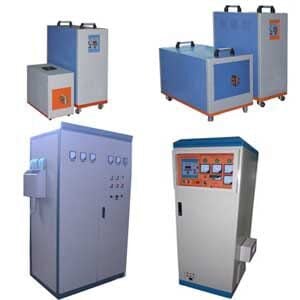
HLQ Induction Equipment publishes medium-frequency, high-frequency and ultra-high-frequency heating systems, together with induction coils and specialized industrial heating equipment.
There is no universal power rating, frequency or coil arrangement suitable for every custom application. Final equipment selection requires thermal analysis, electrical matching and representative process verification.
Table of Contents
- What Is a Custom Induction Heating System?
- Key Applications
- Suitable Materials
- Working Principle
- Technical Specifications
- Recommended Model Selection
- Process Workflow
- Common Problems and Solutions
- Engineering Selection Guide
- Advantages and Limitations
- Why Choose HLQ?
- 6 Core FAQs
What Is a Custom Induction Heating System?
A custom induction heating system is a heating solution designed to transfer electromagnetic energy into a particular conductive workpiece or an appropriate conductive heating element.
The system converts electrical power into alternating current at a selected operating frequency. This current passes through an induction coil, creating a changing magnetic field.
When an electrically conductive workpiece is exposed to the magnetic field, induced electrical currents generate heat within the material.
Custom engineering is necessary because the electromagnetic and thermal behavior depends on the material, electrical conductivity, magnetic permeability, geometry, heating objective and operating conditions.
Standard Induction Heater Versus Custom Induction Heating System
| Engineering Area | Standard Equipment | Custom-Engineered System |
|---|---|---|
| Workpiece | Designed for an established range of parts | Designed around the specified component or production family |
| Power supply | Fixed published model range | Selected to match the required heating duty |
| Operating frequency | Limited to the selected generator’s operating range | Chosen after evaluating electromagnetic coupling and process requirements |
| Induction coil | Standard or interchangeable coil | Custom coil geometry and electrical matching |
| Workpiece positioning | Manual or standard fixture | Application-specific fixture or handling system |
| Temperature control | Available equipment control functions | Application-specific measurement and control arrangement |
| Production integration | Standalone or limited integration | May include conveyors, scanners, robots or PLC integration |
| Acceptance criteria | Equipment function checks | Specified workpiece and process-performance tests |
Induction heating can be used for both localized surface treatment and larger-volume heating, depending on the frequency, coil design, material properties and heating duration.
For background on the electromagnetic process, see induction heating fundamentals.
Key Applications
1. Custom Induction Brazing Systems
Induction brazing uses electromagnetic heating to raise suitable components and a brazing filler metal to the required joining temperature.
The correct joining process depends on the base materials, filler-metal composition, joint clearance, surface condition, atmosphere or flux requirements and the required joint quality.
Typical workpieces include copper tube joints, electrical connectors, carbide tools and selected metal assemblies.
Induction brazing equipment may use helical, pancake, split or specially shaped coils according to the joint geometry.
For specialized joining equipment, see industrial induction brazing equipment.
2. Induction Surface Hardening
Induction surface hardening is used for suitable hardenable steels and cast irons when a hardened surface layer is required.
The workpiece is heated to the specified austenitizing condition and then quenched according to the approved heat-treatment procedure.
Common applications include shafts, gear teeth, pins, bearing components and mechanical transmission parts.
Achievable hardness and case depth depend on the alloy, starting condition, heating profile and quenching conditions.
For detailed equipment information, see induction hardening machines.
3. Induction Forging Preheating
Induction forging heaters raise metal billets, bars and blanks to a temperature suitable for the intended forming process.
Industrial systems may incorporate automatic feeding, sequential heating zones, temperature monitoring and billet transfer equipment.
The required power depends on material properties, billet mass, temperature rise, heating time and production throughput.
4. Induction Melting
Coreless induction melting systems use an alternating magnetic field to generate electrical currents and heat in a conductive metal charge.
Applications include melting selected grades of steel, cast iron, copper, brass, bronze and aluminum.
Furnace selection must consider metal chemistry, batch mass, melting temperature, latent heat, refractory requirements, electrical supply and cooling-system capacity.
Different metal charges may require different furnace designs, operating frequencies and refractory materials.
5. Induction Welding Preheating and PWHT
Induction heating can be used to preheat metal around a weld region or provide controlled post-weld thermal treatment.
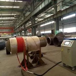
Suitable systems may employ rigid coils or flexible induction heating cables with insulation and temperature-monitoring equipment.
Actual preheat, interpass and post-weld heat-treatment temperatures depend on the welding procedure, material specifications and applicable fabrication code.
6. Induction Shrink Fitting
Induction heating can raise the temperature of a ring, sleeve or housing to produce thermal expansion before assembly.
The required temperature rise depends on the interference fit, component dimensions, material expansion coefficient and assembly clearance.
The final assembly must be evaluated for dimensional accuracy, material limits and mechanical integrity.
7. Annealing and Stress Relief
Induction annealing and stress-relief systems are used where a defined thermal cycle is required to modify the material condition.
The appropriate temperature, holding time and cooling procedure depend on the alloy grade and required final properties.
Induction heating alone does not establish completion of a specified metallurgical treatment.
8. Specialized Industrial Heating
Other potential applications include reactor and vessel heating, steel-pipe heating, thermal assembly, selected coating-removal processes and engineered thermal systems.
For processes involving liquids, powders or nonconductive materials, an appropriate conductive vessel, tube or susceptor may be used to transfer heat indirectly.
Such applications require additional heat-transfer and process-safety engineering.
Representative Application Comparison
| Application | Typical Workpiece | Heating Objective | Critical Verification |
|---|---|---|---|
| Induction brazing | Copper tubes or metal joints | Heat the joint to support filler-metal flow | Joint quality and appropriate joining procedure |
| Surface hardening | Steel shaft or gear | Establish the required surface-hardening condition | Hardness, case depth and microstructure |
| Forging preheat | Steel billet or bar | Heat material for subsequent deformation | Temperature uniformity and throughput |
| Induction melting | Conductive metal charge | Melt the specified alloy | Melt chemistry, temperature and furnace safety |
| Welding preheat | Steel pipe or welded component | Achieve the specified preheat condition | Temperature control and welding procedure compliance |
| Shrink fitting | Ring, sleeve or housing | Produce sufficient thermal expansion | Expansion clearance and finished assembly |
Suitable Materials
Induction heating requires electrical conductivity in the workpiece or in an associated conductive heating element.
Electrical conductivity, magnetic permeability, thermal conductivity, specific heat and component geometry all influence heating behavior.
Material Suitability Matrix
| Material | Electromagnetic Characteristics | Common Industrial Applications | Engineering Consideration |
|---|---|---|---|
| Carbon steel | Conductive; commonly ferromagnetic below its magnetic transformation region | Forging, hardening, preheating and selected heat treatments | Magnetic and thermal properties change with temperature |
| Alloy steel | Conductivity and magnetic response depend on composition and temperature | Hardening, forging, tempering and welding preparation | Material-specific thermal treatment is required |
| Austenitic stainless steel | Conductive; generally low magnetic permeability in the annealed condition | Heating, brazing and solution treatment | Electrical coupling and material properties differ from carbon steel |
| Copper | Very high electrical conductivity and thermal conductivity | Brazing, melting, annealing and electrical-part heating | Coil coupling and heat conduction require careful evaluation |
| Brass and bronze | Conductive copper alloys | Melting, brazing, annealing and forming preparation | Exact alloy composition must be established |
| Aluminum | High conductivity; not ferromagnetic | Billet heating, melting and selected heat treatments | Requires suitable coil and frequency selection |
| Nickel-based alloys | Electrical and magnetic behavior varies by alloy | Heating, brazing and specialized heat treatments | Thermal cycle must match the particular alloy |
| Nonconductive materials | Do not ordinarily couple directly by conventional eddy-current induction | Indirect heating where technically appropriate | A conductive susceptor or vessel may be required |
The material descriptions above explain induction-heating feasibility. They are not performance guarantees or universal heat-treatment recipes.
Working Principle
Induction heating operates through electromagnetic induction and electrical resistance heating.
A power supply converts industrial electrical input into controlled alternating current. The current passes through a matched induction coil, creating a changing magnetic field.
When a conductive workpiece is exposed to the changing field, electrical currents are induced inside it. The interaction between these currents and the material’s electrical resistance generates heat.
For ferromagnetic workpieces, magnetic properties may also influence energy transfer, particularly below the temperature at which ferromagnetic behavior is lost.
Basic Energy-Transfer Sequence
- Industrial electrical power enters the induction heating generator.
- The generator produces alternating current at its operating frequency.
- An electrical matching network couples the generator to the induction coil.
- The coil produces a time-varying magnetic field.
- Electrical currents are induced within the conductive workpiece.
- Electrical resistance generates heat within the material.
- Thermal conduction and process conditions determine the resulting temperature distribution.
Fundamental Engineering Parameters
| Parameter | Effect | Required Engineering Evaluation |
|---|---|---|
| Electrical conductivity | Influences induced-current distribution and heating behavior | Use relevant material properties over the operating temperature range |
| Magnetic permeability | Influences electromagnetic coupling and penetration | Account for temperature-dependent magnetic response |
| Operating frequency | Influences electromagnetic skin depth | Select according to workpiece material, geometry and heating objective |
| Coil geometry | Determines magnetic-field distribution | Match the coil to the actual component and process |
| Coil-to-part clearance | Affects coupling and repeatability | Use suitable mechanical positioning |
| Heating time | Influences temperature rise and thermal diffusion | Validate the complete time-temperature cycle |
| Cooling | Protects equipment and may determine material properties | Separate coil cooling from workpiece-process cooling |
The design of custom induction heating coils is a central part of achieving the required workpiece heating distribution.
Technical Specifications
A custom induction heating system does not have one universal set of technical specifications.
Its electrical, thermal, mechanical and control parameters must be selected for the intended industrial application.
Verified Published HLQ Equipment Examples
| HLQ Model | Published Electrical Rating | Published Frequency Range | Published Supply |
|---|---|---|---|
| DW-HF-45KW | 45 kVA maximum oscillation capacity | 30–80 kHz | Three-phase 380 V, 50–60 Hz |
| DW-HF-60KW | 60 kVA oscillation capacity | 30–80 kHz | Refer to exact equipment specification |
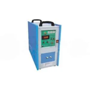
| DW-UHF-10KW | 10 kW published rated power | 100–500 kHz | Three-phase 380 V |
| DW-MF-70 | 70 kW published maximum input power | 1–20 kHz | Three-phase 380 V ±10% |
These are examples of published HLQ model specifications from separate equipment pages. They are not equipment models verified as originally listed on this custom-applications page.
The figures in the rating column represent different electrical quantities. Oscillation capacity in kVA, rated power in kW and maximum input power in kW must not be treated as equivalent values.
Custom System Specification Checklist
| Specification | Required Information |
|---|---|
| Process objective | Brazing, hardening, forging, melting, annealing, preheating or another operation |
| Workpiece material | Exact material grade and relevant condition |
| Workpiece dimensions | Drawing, cross-section, wall thickness and geometry |
| Workpiece mass | Mass of material receiving thermal energy |
| Initial temperature | Actual starting temperature |
| Required temperature | Target process temperature or temperature profile |
| Heating cycle | Heating time, holding period and any required cooling stage |
| Production throughput | Required mass flow or parts per unit time |
| Power supply | Rated capacity and verified operating frequency |
| Induction coil | Application-specific mechanical and electrical design |
| Cooling system | Manufacturer-required cooling conditions and thermal duty |
| Temperature monitoring | Measurement type, range, calibration and recording requirements |
| Electrical utilities | Available voltage, phase, frequency and electrical capacity |
| Safety and control | Guarding, interlocks and relevant process protections |
| Acceptance tests | Measurable quality and performance criteria |
Equipment Function and Verification
| Subsystem | Function | Verification Requirement |
|---|---|---|
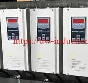
| Power supply | Converts electrical input to controlled alternating-current output | Check model rating and operating limits |
| Matching network | Provides appropriate electrical coupling | Confirm compatibility with generator and coil |
| Induction coil | Produces the electromagnetic field | Inspect geometry, insulation and cooling |
| Workpiece fixture | Controls positioning | Check clearances and repeatability |
| Cooling circuit | Removes heat from equipment components | Verify flow, temperature and relevant alarms |
| Temperature measurement | Measures the thermal process | Validate measurement accuracy and surface assumptions |
| Control system | Coordinates heating and auxiliary functions | Confirm required operating sequence and protections |
Recommended Model Selection
Model selection for a custom induction heating project begins with a defined thermal objective and workpiece description.
The heating generator should not be selected solely by choosing the highest available nominal power rating.
Preliminary Frequency and Equipment Selection
| Heating Requirement | Potential Equipment Family | Reason for Evaluation |
|---|---|---|
| Small precision components | High-frequency or ultra-high-frequency systems | Localized heating and application-specific coil coupling |
| Tube and component brazing | Suitable high-frequency systems | Heating concentrated near a specified joint region |
| Surface hardening | Frequency and power selected according to case-depth requirements | Control of surface heating and quenching |
| Billet forging preheat | Suitable medium-frequency systems | Evaluation of through-heating and production mass flow |
| Metal melting | Matched induction melting furnace | Furnace capacity, metal charge and melting duty |
| Large-component welding preheat | Application-specific induction preheating system | Control of heating coverage and temperature |
| Special-shaped components | Custom coil and fixture arrangement | Geometry-specific electromagnetic coupling |
These are qualitative engineering selection criteria, not guaranteed model recommendations for a particular workpiece.
Published specifications for individual induction heating power supplies should be used only after the required heating duty and frequency range have been established.
Process Workflow
A custom induction heating project should follow a documented engineering process.
Step 1 — Define the Application Requirements
Establish the heating objective, material condition, production requirement and finished-product acceptance criteria.
Step 2 — Verify Material and Workpiece Geometry
Confirm the exact material grade, dimensions, mass, surface condition and relevant drawings.
Step 3 — Estimate Thermal Load
Estimate the required thermal energy using the actual material properties and temperature change.
Include relevant process losses and any phase-change energy where applicable.
Step 4 — Select Power and Frequency
Evaluate the appropriate generator rating and operating frequency range.
Account for the material properties, heating depth, process time and electrical matching requirements.
Step 5 — Design the Coil and Fixture
Develop the induction coil and workpiece positioning system for the actual component geometry.
Verify mechanical clearances and relevant cooling provisions.
Step 6 — Establish Utilities and Safety
Confirm electrical supply, cooling, ventilation, guarding, interlocks and other required auxiliary systems.
Step 7 — Conduct Representative Heating Trials
Use representative samples to evaluate the selected equipment arrangement and thermal response.
Step 8 — Measure Process Results
Record relevant temperatures, cycle times, material properties and inspection results.
Step 9 — Validate the Final Configuration
Compare measured results with the documented project acceptance criteria.
Finalize the equipment configuration only after the relevant process requirements have been demonstrated.

Common Problems and Solutions
| Problem | Possible Cause | Recommended Engineering Action |
|---|---|---|
| Insufficient heating rate | Inadequate absorbed power or poor electromagnetic coupling | Review thermal duty, generator loading and coil design |
| Uneven temperature distribution | Workpiece geometry, coil shape or positioning differences | Evaluate the heating pattern and measurement locations |
| Overheating | Excessive energy input or inadequate temperature control | Validate the thermal cycle and protective limits |
| Unstable electrical matching | Coil and matching network incompatible with generator | Verify the resonant circuit and equipment operating range |
| Coil overheating | Insufficient cooling or unsuitable coil construction | Inspect cooling-water flow and coil condition |
| Inconsistent production results | Material variation, positioning or process-control variation | Improve traceability and validate the process controls |
| Incorrect heat-treatment result | Unsuitable temperature-time cycle or cooling procedure | Review the material specification and metallurgical acceptance tests |
| Unexpected component distortion | Thermal gradients or insufficient mechanical support | Review heating distribution, fixtures and cooling conditions |
| Surface oxidation | Unsuitable temperature, atmosphere or exposure duration | Review material-specific atmosphere and surface requirements |
| Unverified energy savings | No measured electrical and process comparison | Collect comparable production and energy data before making claims |
Engineering Selection Guide
1. Define the Heating Objective
Determine whether the process requires brazing, melting, hardening, annealing, forging preparation, thermal expansion or another outcome.
Each operation has different material and process requirements.
2. Identify the Exact Material
Use the specified material grade and relevant mechanical, electrical and thermal properties.
Values for a different alloy should not be substituted without justification.
3. Calculate Workpiece Mass
For a known material and geometry:
m = ρ × V
Where:
- m = workpiece mass, kg
- ρ = material density, kg/m³
- V = material volume, m³
When only a selected section is heated, its effective thermal mass and heat conduction into adjacent material must be considered.
4. Estimate Sensible Heating Energy
The sensible thermal-energy requirement can be estimated using:
Q = m × integral[cp(T)dT]
The integral is evaluated from the initial temperature to the required final temperature.
Where cp(T) represents the temperature-dependent specific heat capacity.
This is a general engineering equation. It must be evaluated using appropriate material data.
5. Account for Melting and Phase Changes
For melting applications, the total energy requirement also includes the applicable latent heat of fusion and other process energy demands.
Thermal losses, furnace conditions and relevant process characteristics must be evaluated separately.
6. Estimate Electrical Power
A preliminary electrical power estimate may be written as:
P = Q / (η × t)
Where:
- P = estimated average electrical input power, W
- Q = required thermal energy, J
- η = assumed overall electrical-to-useful-heat efficiency
- t = required heating duration, s
The efficiency term must be established or justified for the actual equipment and process.
No universal efficiency value can be assigned to every induction heating application.
7. Evaluate Electromagnetic Penetration
Electromagnetic penetration depends on frequency, electrical resistivity and magnetic permeability.
Under suitable simplifying assumptions, skin depth is expressed as:
δ = sqrt[2ρe / (ωμ)]
Where:
- δ = electromagnetic skin depth, m
- ρe = electrical resistivity, ohm-meter
- ω = angular frequency, rad/s
- μ = magnetic permeability, H/m
Material electrical and magnetic properties may change significantly during heating.
A simplified skin-depth estimate does not by itself predict complete workpiece temperature uniformity.
8. Design the Induction Coil
Select the coil geometry according to the required heating region and workpiece shape.
Possible arrangements include helical coils, pancake coils, split coils and other application-specific forms.
Electrical matching, cooling, insulation and mechanical stability must be evaluated.
9. Select Temperature Monitoring
Choose appropriate thermocouple or infrared temperature measurement methods.
Infrared measurement may require attention to emissivity, surface condition and reflected radiation.
10. Design Cooling and Safety Systems
Cooling requirements depend on the actual generator, coil, workhead and process duty.
Equipment cooling must be distinguished from any workpiece quenching or cooling operation.
Appropriate guarding, electrical isolation, emergency-stop functions and relevant interlocks should be included according to the installation requirements.
11. Evaluate Automation
Industrial systems may include part feeding, position control, scanning mechanisms, robotic handling and process-data recording.
Automation design must reflect the complete cycle time and specified safety requirements.
12. Validate the Application
Representative trials should establish whether the selected system achieves the required heating profile and final component quality.
The documented acceptance results are more reliable than claims based only on nominal generator ratings.
Conceptual Equipment Layout
A typical custom induction heating installation may include an electrical supply, induction generator, matching network, induction coil, workpiece fixture, cooling circuit, temperature monitoring and suitable safety guarding.
Additional equipment may be required for automation, protective atmospheres, quenching, melting or other specialized processing.
Advantages and Limitations
Potential Advantages
- Localized heating: Appropriate coils can concentrate electromagnetic energy in a selected region.
- Non-contact energy transfer: The workpiece can be heated without direct contact with a flame.
- Electrical controllability: Compatible induction equipment permits controlled electrical operation.
- Automation integration: Heating stations can be combined with suitable industrial handling systems.
- Process repeatability: Controlled positioning and verified process settings can improve consistency.
- Application-specific equipment: Custom coils and fixtures allow equipment to be adapted to particular workpiece shapes.
Limitations
- Direct induction heating requires electrical conductivity in the heated element.
- Coil geometry and frequency must be compatible with the workpiece and process.
- Some applications require additional atmosphere control or workpiece cooling.
- Temperature uniformity must be verified rather than assumed.
- Nonstandard workpieces may require prototype coils and process trials.
- Mechanical or metallurgical results depend on the actual material and process.
- Nominal equipment power does not equal useful heat absorbed by the workpiece.
- Energy savings and productivity improvements require measured evidence.
Why Choose HLQ?
HLQ Induction Equipment Co., Ltd. publishes industrial induction heating machines and customized heating equipment for brazing, hardening, forging, melting, preheating and related thermal processes.
Its published product range includes medium-frequency, high-frequency and ultra-high-frequency systems, together with induction heating coils and application-specific equipment.
Custom equipment development should be based on the required workpiece heating result, not on generator rating alone.
Relevant HLQ Engineering Scope
| Engineering Area | Published Equipment or Service Scope |
|---|---|
| Induction power supplies | Medium-frequency, high-frequency and ultra-high-frequency product families |
| Induction coils | Application-specific coil configurations |
| Thermal process development | Power, temperature and heating-cycle assessment |
| Fixtures and handling | Workpiece positioning and manufacturing integration |
| Cooling-system matching | Equipment cooling provisions according to installation requirements |
| Process verification | Testing appropriate to the selected material and application |
For an overview of HLQ’s published industrial equipment and customization scope, see custom induction heating engineering solutions.
Typical Custom Induction Heating Application Illustrations
The following application comparison illustrates six established induction-heating process categories.
These are conceptual examples. They are not presented as measured customer installations, and no invented performance figures are assigned.
| Application Illustration | Required Heating Function | Final Result to Verify |
|---|---|---|
| Copper tube brazing | Heat a specified metal joint | Acceptable completed braze joint |
| Steel shaft hardening | Heat the intended surface region before quenching | Specified hardness and case characteristics |
| Steel billet forging preheat | Heat a billet for subsequent forging | Temperature distribution and forming suitability |
| Metal melting furnace | Supply thermal energy to the metal charge | Required melt condition and composition |
| Pipeline welding preheat | Heat the required area around a weld | Specified preheat conditions |
| Shrink fitting | Heat a fitted component to provide thermal expansion | Assembly clearance and final fit |
6 Core FAQs
1. What is a custom induction heating system?
A custom induction heating system is an electromagnetic heating solution engineered for a particular workpiece and industrial process. It combines an appropriately selected power supply, induction coil, electrical matching, workpiece handling and the required control and cooling systems.
2. Which industrial processes can use custom induction heating?
Applications include induction brazing, hardening, forging preheating, melting, annealing, stress relief, welding preheating and shrink fitting. Actual suitability depends on material conductivity, geometry and process requirements.
3. How do engineers select induction heating power and frequency?
Selection depends on the material, workpiece mass and dimensions, heating objective, target temperature, required cycle time and electromagnetic penetration. Thermal calculations, electrical matching and representative heating trials are used to verify the final configuration.
4. Can one induction heating coil be used for different workpieces?
Sometimes, but not universally. Different workpiece dimensions, materials and heating objectives may require different coil configurations. A single coil should only be used across multiple parts when acceptable coupling, thermal performance and repeatability have been demonstrated.
5. Are induction heating systems suitable for continuous automated production?
Yes. Suitable induction heating equipment can be integrated with conveyors, scanning systems, automatic handling, temperature measurement and industrial controls. Production capacity depends on the complete process cycle and verified equipment limits.
6. What information is required to design a custom induction heating system?
The essential information includes material grade, workpiece drawings or dimensions, mass, initial temperature, target temperature, heating time, production quantity, available electrical supply, cooling conditions and required final material properties. Additional information may be needed for atmosphere control, automation or specialized heat-treatment requirements.