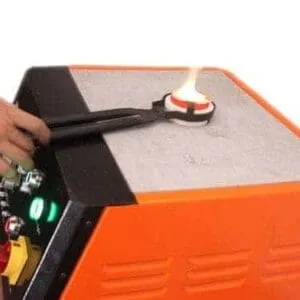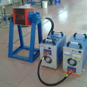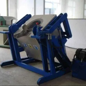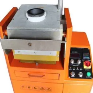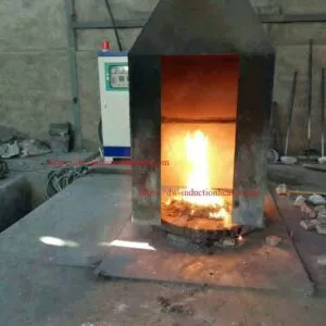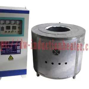

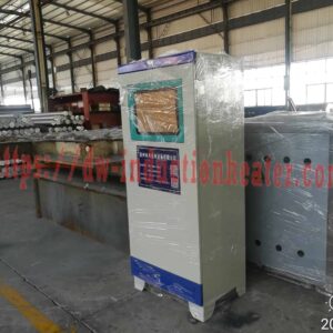
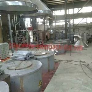

400kg Aluminum Melting Furnace
400 kg Aluminum Melting Furnace: SMJD-1250 Induction Model Guide
Quick Answer
The 400 kg aluminum melting furnace on this HLQ page corresponds to the published SMJD-1250 configuration rated at 80 kW, with a listed 400 kg aluminum charge capacity and 120 A input current. “400 kg” describes the table’s charge capacity; it is not a verified hourly melting rate or recovered metal output. The same model name also appears in a separate 120 kW, 450 kg configuration, so the power rating must accompany the model name.

Table of Contents
- What is the 400 kg Aluminum Melting Furnace?
- Key Applications
- Suitable Materials
- Working Principle
- Technical Specifications
- Recommended Model Selection
- Process Workflow
- Common Problems and Solutions
- Engineering Selection Guide
- Advantages and Limitations
- Why Choose HLQ?
- 6 Core FAQs
What is the 400 kg Aluminum Melting Furnace?
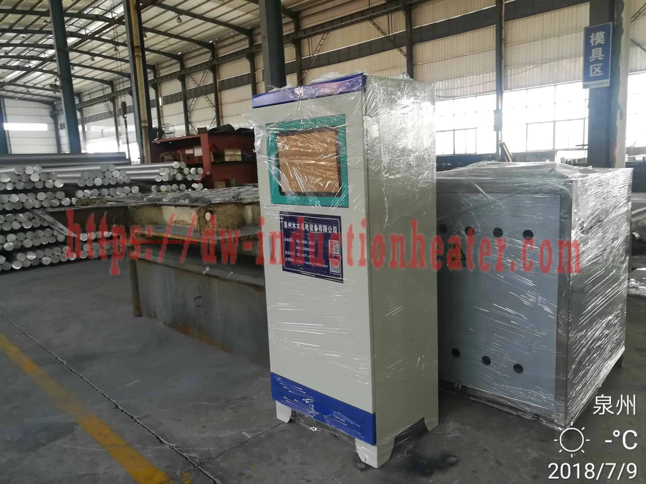
It is the 80 kW SMJD-1250 induction furnace configuration identified in the published aluminum capacity table. The page also displays the wider SMJD series, but those other rows are separate capacity and power options. The furnace is listed under HLQ’s aluminum melting furnace, induction melting furnace, and metal melting furnace categories.
| Item | Published value | Meaning |
|---|---|---|
| Model and configuration | SMJD-1250, 80 kW | Distinguishes it from the 120 kW SMJD-1250 row. |
| Aluminum capacity | 400 kg | Listed charge capacity, not kg per hour. |
| Input current | 120 A | Value in the linked electrical parameter table. |
| Crucible specification | 1250# | One crucible dimension row is published for SMJD-1250. |

Key Applications
The original description names aluminum smelting and casting. For the 400 kg configuration, the documented furnace role is melting an approved aluminum charge before a separately defined transfer or casting step. The page does not give a measured cycle time, hourly production rate, or a complete downstream equipment list. For a wider production scope, HLQ separately lists an aluminum ingot melting production line.
| Application path | Role of the 400 kg furnace | Information still required |
|---|---|---|
| Aluminum casting feed | Melt a defined aluminum charge | Transfer arrangement, casting method, and quality criteria |
| Aluminum alloy melting | Melt a charge within the published aluminum capacity reference | Specific alloy and operating procedure |
| Prepared secondary aluminum feed | Potential melting stage after feedstock assessment | Preparation method and measured recovery for the actual feed |

The illustration below shows material routes named in the source table. It is not a documented customer installation or a measured recovery study.

Suitable Materials
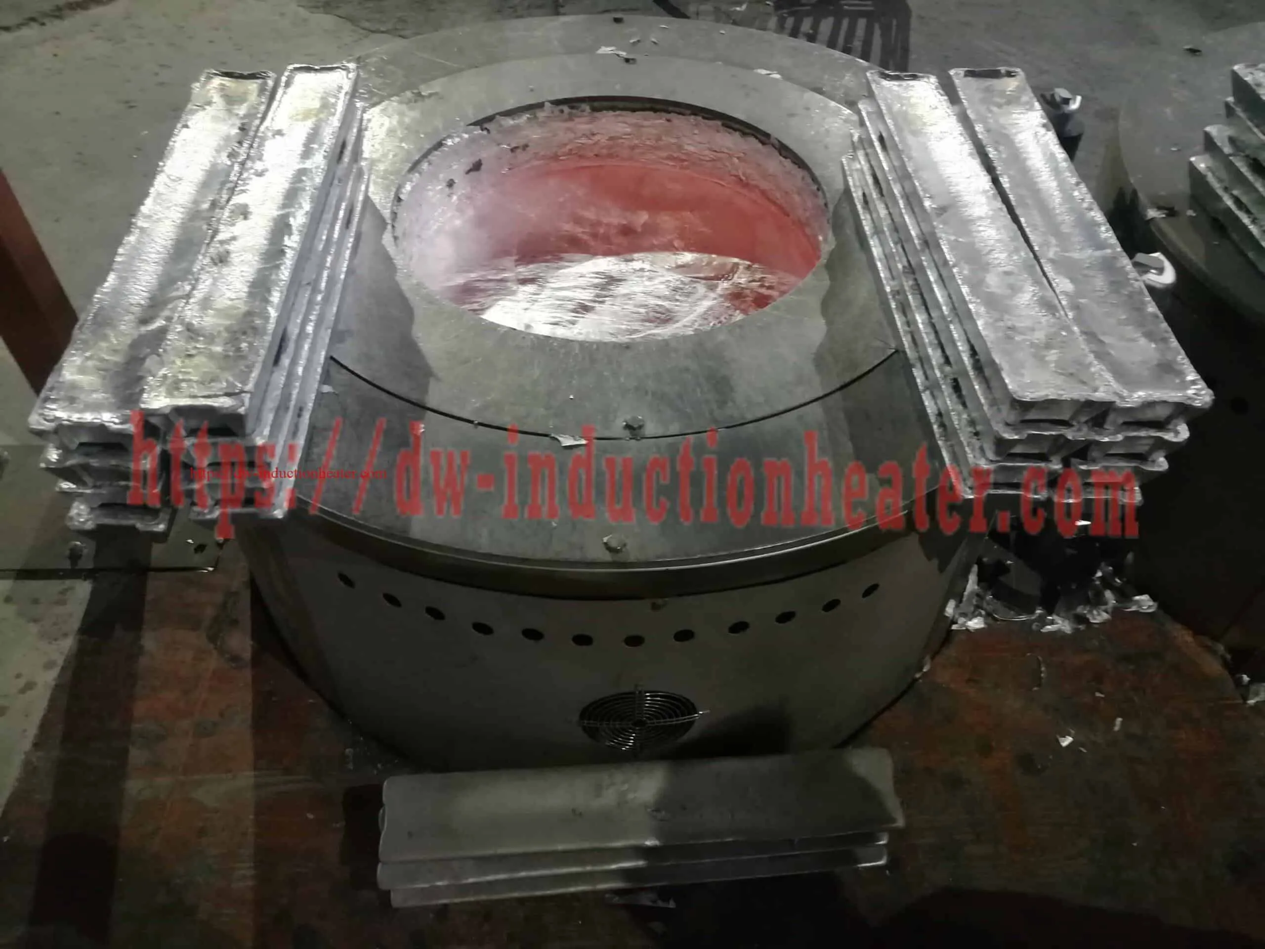
The source table groups aluminum, aluminum alloy, aluminum scrap, aluminum slag, and pop cans under one aluminum capacity heading. This identifies material topics on the page; it does not establish equal metal yield, equal melting time, or the suitability of every unprepared feed. Feed composition and condition need separate evaluation, especially for scrap, slag, and used cans.
| Material named by the page | Supported statement | Unverified for this 400 kg configuration |
|---|---|---|
| Aluminum and aluminum alloy | The SMJD-1250 80 kW row lists 400 kg in the aluminum column. | Alloy-specific cycle time and melt quality. |
| Aluminum scrap | Scrap appears in the source column heading. | Recovery yield and acceptable contamination range. |
| Aluminum slag | Slag appears in the source column heading. | Recoverable metal content and process method. |
| Pop cans | Pop cans appear in the source column heading. | Preparation requirements and recovered-metal output. |
HLQ presents aluminum can recycling equipment on a separate page. Its equipment scope should not be assumed to be included with this furnace.
Working Principle
The linked HLQ manual describes alternating current in an induction coil creating a changing magnetic field. It describes induced currents heating a conductive crucible and transferring heat to the aluminum charge. The actual coil, crucible, cooling, and control arrangement should be checked for the selected build. See the original induction melting furnace manual and HLQ’s basic induction heating guide.

The following diagram explains the documented heat path. It is a conceptual illustration, not an electrical or mechanical installation drawing.

Technical Specifications
The table below preserves all 13 configurations shown on the original product page. The first SMJD-1250 row is the page’s 400 kg configuration. The linked parameter PDF supplies the input-current values. Its capacity table labels kW as “Input Power,” while its electrical table labels the corresponding kW figures as “Output Power”; the electrical definition needs confirmation for a final specification.
| Model | Listed power (kW) | Steel/stainless steel (kg) | Copper/gold/silver (kg) | Aluminum column (kg) | Input current (A) |
|---|---|---|---|---|---|
| SMJD-463 | 60 | 200 | 500 | 200 | 90 |
| SMJD-480 | 60 | 150 | 500 | 150 | 90 |
| SMJD-580 | 80 | 200 | 600 | 200 | 120 |
| SMJD-600 | 60 | 230 | 560 | 230 | 90 |
| SMJD-900 | 120 | 300 | 900 | 300 | 180 |
| SMJD-905 | 80 | 300 | 900 | 300 | 120 |
| SMJD-1250: 400 kg option | 80 | 400 | 1,200 | 400 | 120 |
| SMJD-1250: 450 kg option | 120 | 450 | 1,350 | 450 | 180 |
| SMJD-1500 | 120 | 500 | 1,500 | 500 | 180 |
| SMJD-1550 | 120 | 520 | 1,560 | 520 | 180 |
| SMJD-1700 | 160 | 600 | 1,700 | 600 | 240 |
| SMJD-2300 | 160 | 800 | 2,000 | 800 | 240 |
| SMJD-3100 | 200 | 1,200 | 3,000 | 1,200 | 300 |

The source table carries an “1800°C max” heading. It is not a recommended aluminum melt temperature. The SMJD parameter PDF also states a three-phase 380 V, 50–60 Hz supply and a customizable 1–100 kHz series frequency range; it does not publish a fixed frequency for each listed model.
| Model | Crucible code | A: upper outer diameter | B: upper inner diameter | C: bottom outer diameter | H: total height |
|---|---|---|---|---|---|
| SMJD-463 | 463# | 565 | 500 | 310 | 617 |
| SMJD-480 | 480# | 510 | 420 | 400 | 710 |
| SMJD-580 | 580# | 420 | 360 | 300 | 840 |
| SMJD-600 | 600# | 620 | 525 | 620 | 470 |
| SMJD-900 | 900# | 520 | 425 | 510 | 960 |
| SMJD-905 | 905# | 620 | 530 | 620 | 650 |
| SMJD-1250 | 1250# | 620 | 535 | 620 | 850 |
| SMJD-1500 | 1500# | 735 | 640 | 460 | 900 |
| SMJD-1550 | 1550# | 775 | 682 | 400 | 750 |
| SMJD-1700 | 1700# | 610 | 500 | 610 | 1,200 |
| SMJD-2300 | 2300# | 880 | 775 | 355 | 1,000 |
| SMJD-3100 | 3100# | 780 | 645 | 780 | 1,400 |
The PDF gives dimensional tolerances of ±10 mm for A, C, and H, and ±5 mm for B. It publishes one SMJD-1250 crucible row even though two SMJD-1250 power and capacity configurations appear in the furnace table.
Recommended Model Selection
For a nominal 400 kg aluminum charge, the published match is SMJD-1250 at 80 kW. Compare adjacent options only when the intended charge, operating schedule, and electrical supply justify them. The table does not provide melting time or kg/h output. HLQ’s separate aluminum melting plant equipment page discusses a wider project context, but its published furnace capacities should still be read as charge values.
| Configuration | Listed power | Aluminum capacity | Input current | Selection distinction |
|---|---|---|---|---|
| SMJD-905 | 80 kW | 300 kg | 120 A | Lower listed aluminum capacity. |
| SMJD-1250, 400 kg option | 80 kW | 400 kg | 120 A | Configuration matching this page title. |
| SMJD-1250, 450 kg option | 120 kW | 450 kg | 180 A | Same model name, different published configuration. |
| SMJD-1500 | 120 kW | 500 kg | 180 A | Higher listed aluminum capacity. |

Process Workflow
A process plan should identify the charge before it assigns the melting step to the 400 kg furnace. Casting, holding, and scrap preparation are downstream or upstream interfaces unless separately defined in the equipment scope.
- Identify the aluminum alloy or feedstock and its condition.
- Prepare an approved charge and check its mass against the selected configuration.
- Verify the furnace, crucible, electrical supply, and applicable operating procedure.
- Melt and assess the metal against the required process criteria.
- Transfer to the specified holding or casting operation.

The page links to an aluminum scrap recycling process document. That document provides general process context; it is not a measured SMJD-1250 melting trial. HLQ also lists a separate aluminum scrap recycling furnace product page.

Common Problems and Solutions
These are selection and process checks, not a diagnosis of a particular installed furnace. Follow the documentation supplied for the actual machine when operating or troubleshooting it.
| Concern | What the source establishes | Practical check |
|---|---|---|
| 400 kg is mistaken for kg/h | The figure appears in a melting-capacity table. | Establish an actual cycle time before calculating production rate. |
| Two SMJD-1250 rows are confused | 80 kW/400 kg and 120 kW/450 kg are separate rows. | Identify the exact power, capacity, and current together. |
| Scrap or can yield is assumed from the table | The column heading names these feeds but gives no recovery test. | Assess the actual feed and define a suitable preparation and yield basis. |
| Electrical requirements are unclear | The documents use both “Input Power” and “Output Power” labels. | Resolve the rating definition and site supply requirements in the final electrical specification. |

Engineering Selection Guide
The 400 kg row is a starting point for engineering selection. The source provides a crucible envelope but does not provide the installed furnace footprint, required clearances, cooling specification, measured cycle time, or a dimensioned plant layout.
| Selection item | Published for the 400 kg option | Still to define |
|---|---|---|
| Furnace configuration | SMJD-1250; 80 kW; 400 kg aluminum; 120 A | Final electrical rating definition and delivered build |
| Series electrical data | Three-phase 380 V, 50–60 Hz; customizable 1–100 kHz series range | Confirmed site supply and selected operating frequency |
| 1250# crucible | A 620 mm; B 535 mm; C 620 mm; H 850 mm | Installation fit, access, and replacement method |
| Production rate | No verified kg/h figure | Measured or agreed charge cycle and production schedule |
| Plant arrangement | No dimensioned layout | Feed route, power/control position, services, and metal transfer route |
The following top-view graphic identifies functional relationships only. Its boxes are not drawn to scale, and the listed crucible dimensions are not floor-plan dimensions.

Advantages and Limitations
| Useful published information | Limit of the published information |
|---|---|
| The 400 kg option has an identified model, power rating, and current value. | No verified melting time or hourly output is supplied. |
| The 1250# crucible has published dimensions and tolerances. | These are not complete furnace or installation dimensions. |
| The original parameter sheet and furnace manual are available. | Input versus output power labeling needs confirmation. |
| The aluminum column names several feed forms. | Feed-specific recovery, slag processing, and can preparation are not quantified. |
HLQ’s induction melting versus resistance and gas melting overview provides a broader comparison. Any efficiency or operating-cost conclusion should use defined process conditions and measured data.
Why Choose HLQ?
HLQ provides a model-by-model SMJD capacity table, an electrical parameter table, crucible dimensions, and a furnace manual for this product family. For the page titled “400kg Aluminum Melting Furnace,” these documents identify a specific 80 kW SMJD-1250 configuration and make the neighboring 450 kg configuration distinguishable. They also show which production and installation details still need project-level definition.
6 Core FAQs
1. Which published model matches the 400 kg page title?
The 80 kW SMJD-1250 row lists 400 kg aluminum capacity and 120 A input current.
2. Is 400 kg the hourly melting output?
No. It is the aluminum capacity listed in the source table. The page does not publish a verified melt cycle or kg/h output.
3. Is every SMJD-1250 furnace a 400 kg, 80 kW unit?
No. The source also lists SMJD-1250 at 120 kW, 450 kg aluminum capacity, and 180 A.
4. What are the published 1250# crucible dimensions?
The parameter PDF lists A 620 mm, B 535 mm, C 620 mm, and H 850 mm. Its tolerances are ±10 mm for A, C, and H, and ±5 mm for B.
5. Does the 400 kg figure guarantee 400 kg of recovered metal from scrap, slag, or cans?
No. The source names those feed categories but provides no feed-specific recovery yield. Actual output depends on the material and process used.
6. What electrical supply does the SMJD document list?
It states three-phase 380 V at 50–60 Hz for the series and a customizable 1–100 kHz frequency range. The selected machine’s electrical rating should also resolve the documents’ “Input Power” and “Output Power” labels.