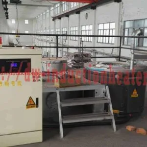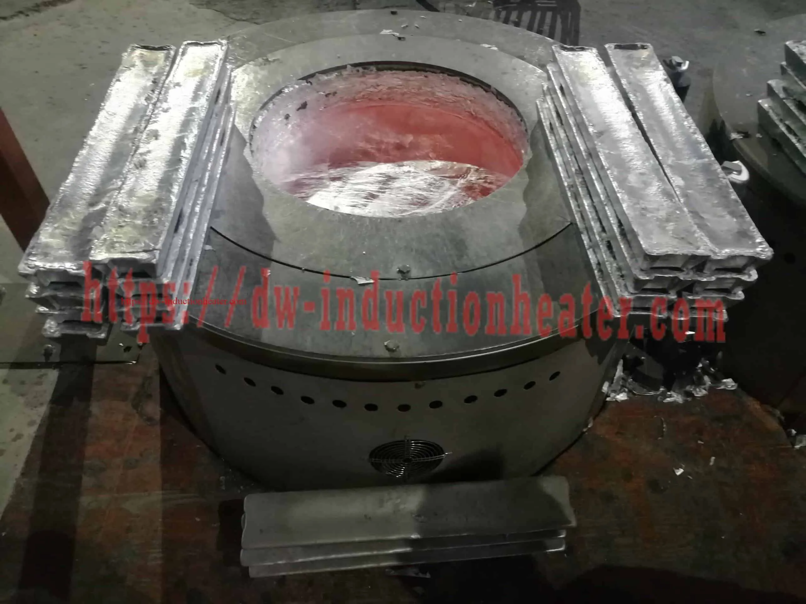

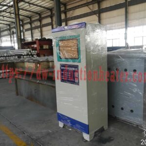
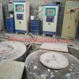
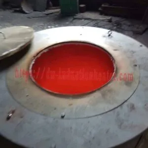
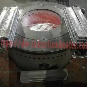
Aluminum Melting Oven
Aluminum Melting Oven and Furnace: Induction Heat Compared with Gas, Diesel and Resistance Melting
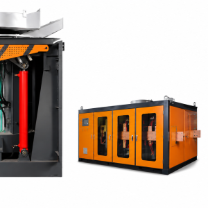
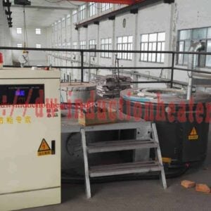
An aluminum melting oven and an aluminum melting furnace are, in most cases, the same machine described with two different nouns. HLQ builds that machine as a coreless electric induction crucible furnace: the heat is generated inside the conductive crucible itself and then passes into the aluminum charge, so no flame and no combustion gas ever touch the metal. This page sets out what the published HLQ equipment range actually delivers for aluminium, what the published specification tables say, and where an induction melting oven differs from the gas-fired, oil-fired and resistance-heated furnaces it is normally bought to replace.
Three published HLQ families cover aluminium melting: the DW-MF medium-frequency series for small batches, the SMJD production series, and the hydraulic tilting furnace range for foundry-scale batches. The figures quoted on this page are taken from the published HLQ product pages, the SMJD parameter sheet and the HLQ induction melting furnace manual, and are reproduced without adjustment.

Quick Answer
The HLQ aluminum melting oven and furnace is a batch electric induction crucible furnace. A clean, dry charge is charged into the crucible, melted at full power with electromagnetic stirring, held in the aluminium operating range, skimmed of the floating residue, and tilted into a ladle or into refractory-lined moulds. Temperature is set by the power supply rather than by a flame, and is held by PID control on an LED digital controller with a published accuracy of up to 3 °C.
Aluminum melting oven and furnace — the key published figures at a glance
| Parameter | Published value |
|---|---|
| Small-batch family | DW-MF, 8 models from DW-MF-15 to DW-MF-160 |
| DW-MF input power | 15 kW – 160 kW |
| DW-MF aluminum melting ability | 3 kg – 75 kg per heat |
| DW-MF oscillation frequency | 1 kHz – 20 kHz, normally about 4, 8, 11, 15 or 20 kHz according to the application |
| DW-MF duty cycle | 100 %, 24 hours work |
| DW-MF melting time | 30 – 50 minutes per batch; the first melt on a cold furnace takes longer, with about 20 – 30 minutes quoted for a later melt on a hot furnace |
| Production family | SMJD, 13 models from SMJD-463 to SMJD-3100 |
| SMJD input power | 60 kW – 200 kW |
| SMJD input current | 90 A – 300 A |
| SMJD aluminum melting capacity | 150 kg – 1,200 kg per heat |
| Supply | 3-phase 380 V, 50 – 60 Hz, +N |
| SMJD oscillation frequency | 1 kHz – 100 kHz, custom frequency according to customer request |
| Maximum furnace temperature | 1800 °C (furnace rating, not an aluminium setpoint) |
| Aluminum melting point | 660.32 °C (1220.6 °F) |
| Aluminum production melt range | 680 – 760 °C |
| Theoretical heat to melt and hold aluminium at 720 °C | ≈ 0.30 kWh/kg before furnace losses |
| Published energy saving against gas and oil melting | 20 % – 30 % (printed manual). The product pages state 20 % – 40 % against a diesel workshop furnace |
| Furnace lining | Integral polycrystalline mullite fibre, rated above 1200 °C |
| Aluminum crucible and lining | Graphite, SiC-graphite or high-alumina |
| Temperature control | PID heating control, LED digital controller, accuracy up to 3 °C |
| Power devices | IGBT |
| Stirring | Electromagnetic — the melt is mixed by the field |
| Pour method | Hydraulic, gearbox or manual tilt into a ladle or moulds |
| Published product range | Electromagnetic 5 – 5,000 kg aluminum induction melting furnace |
For the wider range of HLQ melting equipment, see the induction furnace family, and for the published guide to the small-batch aluminium route see induction melting aluminum.
Table of Contents
- Quick Answer
- What is the Aluminum Melting Oven and Furnace?
- Key Applications
- Suitable Materials
- Working Principle
- Technical Specifications
- Recommended Model Selection
- Process Workflow
- Common Problems and Solutions
- Engineering Selection Guide
- Advantages and Limitations
- Why Choose HLQ?
- 6 Core FAQs
What is the Aluminum Melting Oven and Furnace?
An aluminum melting oven is a coreless electric melting furnace. Metal is melted to a liquid in the crucible and then poured out, usually into a mould. Unlike a flame furnace, which transfers heat from combustion gases across a refractory wall and into the metal charge, an induction furnace puts the heat into the charge itself. That is why the melt is fast, clean and uniform, why the temperature control is direct rather than indirect, and why no combustion product enters the melt.
The nouns matter commercially because buyers search for this equipment under several names. HLQ publishes the same core machine as an aluminum melting oven, an aluminum melting furnace, an aluminum smelter and an aluminum induction smelter. For the published product families, the ranges and duties, see the aluminum melting oven product page and the melting aluminum furnace product page.
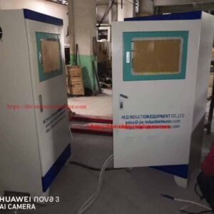
Two distinctions are worth drawing before anything is specified. First, an induction furnace melts metal in a crucible; an induction heater heats a formed part in a coil, and one does not substitute for the other. Second, a reliable induction furnace has to be supplied and specified as a complete system — furnace body, power supply, cooling and safety protection matched to one another — because a mismatch between furnace capacity and power supply produces slow melting, high energy consumption and unstable operation. The published main parts of a medium-frequency melting system are the induction heating generator, the melting furnace and the compensation capacitor.
The comparison that decides most purchases, however, is not between names. It is between the induction oven and the furnace it replaces.

Where the heat comes from — and why the difference matters
| Point of comparison | Induction melting oven | Gas or diesel furnace | Resistance element furnace |
|---|---|---|---|
| Where the heat is generated | Inside the conductive crucible, and from there into the charge | In the flame, outside the vessel; heat crosses the lining to reach the metal | In the element, outside the vessel; heat crosses the lining to reach the metal |
| Combustion gas in contact with the metal | None | Yes — combustion gas and dust reach the workshop, and an auxiliary exhaust pipeline is needed | None |
| Published energy saving against traditional gas and oil melting | 20 % – 30 % | Baseline | Not published as a comparison figure |
| Workshop conditions | Electricity-powered: no air pollution, no dust and little noise | High ambient workshop temperature, exhaust ducting and auxiliary equipment | No combustion products, but the hot element still radiates into the workshop |
| Element or consumable wear | The induction coil is the working part and is water-cooled | The refractory lining is exposed to the flame continuously | The element oxidises in the hot zone, giving shorter service life and higher maintenance |
| Temperature control | Set by the power supply, PID controlled, up to 3 °C accuracy | Burner modulation | Element modulation |
| Metal quality | No combustion products in the melt; electromagnetic stirring mixes the bath | Combustion products can reach the charge | No combustion products in the melt |
| Power supply required | Large electrical capacity: 60 kW – 200 kW on the SMJD series | Fuel supply and burner network | Large electrical capacity |
That comparison is not a marketing claim dressed up as data. Two energy-saving figures are published on HLQ pages and they are not measured against the same baseline. The printed HLQ induction melting furnace manual states 20 % – 30 % saving against traditional melting methods using gas and oil; the product pages state 20 % – 40 % against a diesel workshop furnace. The difference comes from the comparison baseline rather than from the machine, so any figure quoted in a proposal should name the baseline it is measured against. The theoretical heat requirement published for aluminium is approximately 0.30 kWh per kilogram to melt and hold the metal at 720 °C, before furnace losses. Actual consumption is higher because of coil, crucible, lining and radiation losses, and the difference between a well-matched furnace and a badly matched one is where most of the operating cost of aluminium melting is decided.
For the published plant range and the way power scales with batch weight, see the aluminum melting plant equipment guide.
Key Applications
The published applications for the HLQ induction melting range, by industry:
| Industry | Metals | Typical furnace |
|---|---|---|
| Aluminum casting and recycling | Aluminum ingots, Al-Si / Al-Mg / Al-Cu alloys, clean scrap | Hydraulic tilting furnace |
| Scrap recycling | Clean, dry iron, steel, copper and aluminum scrap | Medium-frequency tilting furnace |
| Iron and steel foundries | Gray and ductile iron, carbon and alloy steel, stainless steel | Steel-shell hydraulic tilting furnace |
| Copper and brass foundries | Copper, brass, bronze, cupronickel | Tilting crucible furnace |
| Jewellery and precious metals | Gold, silver | Small gold melter, 0.5 – 30 kg |
| Laboratories and R&D | Trial alloys | Small crucible furnace, 10 – 100 kg |
For the aluminium melting duty specifically, the published applications are:
- Ingot and alloy production. Clean remelt and primary ingot are brought together in the crucible to bring the melt to the alloy the customer needs, at the 680 – 760 °C operating range, ready to cast. HLQ publishes the casting end of the line separately as an aluminum ingot casting machine, the page heading it “Aluminum Ingot Casting Machine For Casting Aluminium-Lead-Zinc Alloy”.
- Secondary remelt. Mixed scrap, extrusion offcuts, machining swarf, profiles and foundry returns melted back to usable metal. The SMJD table lists aluminum scrap, aluminum slag and pop can in the aluminium capacity column, so the furnace is specified for mixed and contaminated feed as well as clean charge.
- Small-batch and laboratory melting. The DW-MF series is published for melting aluminium from 3 kg upwards, alongside gold, silver, copper, bronze, tin, magnesium and stainless steel, with a published melting time of 30 – 50 minutes per batch.
- Heat treatment supply. The SMJD series is published as a melting furnace used ahead of forging, sintering and hot rolling in the casting and melting industries.
- Multi-metal duty on the same cell. The same furnaces are published for aluminium, copper, gold, silver, zinc, steel and stainless steel.
For the wider duty envelope of the range, including the induction metals melting furnace families, see the related product page.

The five published application duties set out above share the same furnace, the same crucible and the same control system. What changes between them is the charge and the required melt quality, and therefore the dross handling and the cycle discipline. An induction melting oven in a casting shop and one in a recycling shop are configured from the same published tables; they are simply run with different charges and different skimming habits.

Suitable Materials
Any conductive metal can be melted, but the lining has to match the metal and the slag it will see. The table below lists the metals published for HLQ induction melting furnaces, with the operating temperatures and the published lining or crucible for each.
| Metal | Typical melting or operating temperature | Published lining or crucible |
|---|---|---|
| Aluminum alloys | Pure Al melts at about 660 °C; usual operating range 680 – 760 °C | Graphite, SiC-graphite or high-alumina |
| Aluminum alloy scrap | Alloy dependent | Published in the SMJD aluminum capacity column |
| Pop cans (used beverage containers) | About 660 °C | Published in the SMJD aluminum capacity column |
| Aluminum slag and dross material | Alloy dependent | Published in the SMJD aluminum capacity column |
| Copper (Cu-ETP) | About 1083 – 1100 °C | Magnesia lining; graphite or SiC crucible on small furnaces |
| Brass / tin bronze | About 850 – 1000 °C | Silica or alumina; graphite or SiC crucible |
| Gray cast iron | About 1150 – 1400 °C | Acidic, neutral or basic refractory lining |
| Ductile iron | About 1300 – 1500 °C | Acidic, neutral or basic refractory lining |
| Carbon steel / low-alloy steel | About 1450 – 1650 °C | Acidic, neutral or basic refractory lining |
| Stainless steel | About 1400 – 1550 °C | Neutral or basic lining |
| Gold | Furnace maximum about 1200 – 1400 °C | Graphite or clay-graphite crucible |
| Zinc alloy | Low temperature | Low-temperature-compatible refractory lining |
For aluminium specifically, the published frequency guidance per metal is aluminium at approximately 0.5 – 20 kHz, copper at 0.25 – 8 kHz, iron and steel at 0.5 – 2.5 kHz and gold at 1 – 80 kHz, with the lower frequency used for the larger furnaces. The DW-MF series itself is published at 1 – 20 kHz, normally about 4, 8, 11, 15 or 20 kHz according to the application, and the SMJD parameter sheet specifies 1 kHz – 100 kHz with custom frequency available according to customer request.
Two aluminium-specific cautions follow from the same published data. Aluminium oxidises, and the oxide floats as dross that has to be skimmed off with a steel ladle and processed separately rather than discarded. And the charge must be clean and dry: water, oil or sealed cavities in scrap can cause violent eruptions in molten metal.

Working Principle
The heating principle is the same for every furnace in this family. Through the internal rectifier and filter circuit the AC supply is converted into DC power; the control circuit then converts that DC power into high-frequency magnetic energy. The high-speed changing current through the coil produces a high-speed changing magnetic field. When the magnetic field lines pass through the crucible, numerous small eddy currents are generated inside it, so the crucible itself is heated at high speed, and that heat is transferred to the aluminum alloy and melted into a liquid state.
Four consequences follow directly from that mechanism, and they explain most of the operating behaviour of an induction melting oven:
- The metal is heated from the outside in. The crucible wall heats first and the heat then travels into the charge, so a large batch has a thermal gradient that the operator manages by the charge order and the melt time.
- The bath is stirred electromagnetically. The same field that heats the metal also moves it, so temperature and composition are more uniform across the melt than in a flame-stirred bath.
- The temperature is set by the power supply. There is no flame to modulate, so the control loop is electrical: PID heating control with an LED digital controller of up to 3 °C accuracy, closed-loop power control to avoid temperature change caused by power-down, and digital phase-locked-loop tracking with automatic load impedance matching.
- Protection is electrical and fluidic. The published protection set covers over-voltage, under-voltage, phase loss, over-current and over-temperature, with real-time parameter display, fault diagnosis and alarm, and an automatic leakage alarm that cuts the power supply and displays the working state.
The background physics is on the HLQ induction heating principle page, and the full published sequence is set out in the Aluminum, Copper, Iron induction melting furnace manual.

Read the diagram from the left. The electrical chain — supply, power supply, capacitor cabinet and control — feeds a water-cooled copper coil around the crucible. The field induces eddy currents in the crucible wall, the wall heats, and that heat passes into the aluminium. The same field produces the stirring that mixes the bath. On the right, the three heat sources are compared on the only axis that matters commercially: where the heat is made, and therefore how much of it is lost before it reaches the metal.

Technical Specifications
1. SMJD melting capacity
| Type | Input Power | Melting capacity — steel, stainless steel | Melting capacity — copper, gold, silver (scrap, slag) | Melting capacity — aluminum, aluminum alloy, aluminum scrap, aluminum slag, pop can | Max temperature |
|---|---|---|---|---|---|
| SMJD-463 | 60 kW | 200 kg | 500 kg | 200 kg | 1800 °C |
| SMJD-480 | 60 kW | 150 kg | 500 kg | 150 kg | 1800 °C |
| SMJD-580 | 80 kW | 200 kg | 600 kg | 200 kg | 1800 °C |
| SMJD-600 | 60 kW | 230 kg | 560 kg | 230 kg | 1800 °C |
| SMJD-900 | 120 kW | 300 kg | 900 kg | 300 kg | 1800 °C |
| SMJD-905 | 80 kW | 300 kg | 900 kg | 300 kg | 1800 °C |
| SMJD-1250 | 80 kW | 400 kg | 1,200 kg | 400 kg | 1800 °C |
| SMJD-1250 | 120 kW | 450 kg | 1,350 kg | 450 kg | 1800 °C |
| SMJD-1500 | 120 kW | 500 kg | 1,500 kg | 500 kg | 1800 °C |
| SMJD-1550 | 120 kW | 520 kg | 1,560 kg | 520 kg | 1800 °C |
| SMJD-1700 | 160 kW | 600 kg | 1,700 kg | 600 kg | 1800 °C |
| SMJD-2300 | 160 kW | 800 kg | 2,000 kg | 800 kg | 1800 °C |
| SMJD-3100 | 200 kW | 1,200 kg | 3,000 kg | 1,200 kg | 1800 °C |
Three notes on this table. The “steel, stainless steel” column is printed identically to the aluminium column in all thirteen rows, in the published sheet and in HLQ’s own manual; confirm the steel figures with HLQ before quoting this table commercially. The two SMJD-1250 entries are retained separately because their published power and capacity differ. The 1800 °C figure is the furnace maximum, not an aluminium operating setpoint — the aluminium melting point is 660.32 °C and the published production melt range is 680 – 760 °C.
The complete published sheet is available as the SMJD induction melting furnace parameter sheet.
2. SMJD main technical parameters
| Type | Output power | Input current | Input voltage | Oscillation frequency |
|---|---|---|---|---|
| SMJD-463 | 60 kW | 90 A | 3-phase 380 V, 50 – 60 Hz, +N | 1 kHz – 100 kHz, custom frequency according to customer request |
| SMJD-480 | 60 kW | 90 A | 3-phase 380 V, 50 – 60 Hz, +N | 1 kHz – 100 kHz, custom frequency according to customer request |
| SMJD-580 | 80 kW | 120 A | 3-phase 380 V, 50 – 60 Hz, +N | 1 kHz – 100 kHz, custom frequency according to customer request |
| SMJD-600 | 60 kW | 90 A | 3-phase 380 V, 50 – 60 Hz, +N | 1 kHz – 100 kHz, custom frequency according to customer request |
| SMJD-900 | 120 kW | 180 A | 3-phase 380 V, 50 – 60 Hz, +N | 1 kHz – 100 kHz, custom frequency according to customer request |
| SMJD-905 | 80 kW | 120 A | 3-phase 380 V, 50 – 60 Hz, +N | 1 kHz – 100 kHz, custom frequency according to customer request |
| SMJD-1250 | 80 kW | 120 A | 3-phase 380 V, 50 – 60 Hz, +N | 1 kHz – 100 kHz, custom frequency according to customer request |
| SMJD-1250 | 120 kW | 180 A | 3-phase 380 V, 50 – 60 Hz, +N | 1 kHz – 100 kHz, custom frequency according to customer request |
| SMJD-1500 | 120 kW | 180 A | 3-phase 380 V, 50 – 60 Hz, +N | 1 kHz – 100 kHz, custom frequency according to customer request |
| SMJD-1550 | 120 kW | 180 A | 3-phase 380 V, 50 – 60 Hz, +N | 1 kHz – 100 kHz, custom frequency according to customer request |
| SMJD-1700 | 160 kW | 240 A | 3-phase 380 V, 50 – 60 Hz, +N | 1 kHz – 100 kHz, custom frequency according to customer request |
| SMJD-2300 | 160 kW | 240 A | 3-phase 380 V, 50 – 60 Hz, +N | 1 kHz – 100 kHz, custom frequency according to customer request |
| SMJD-3100 | 200 kW | 300 A | 3-phase 380 V, 50 – 60 Hz, +N | 1 kHz – 100 kHz, custom frequency according to customer request |
3. SMJD crucible specification
| Type | Specification | Upper mouth outer diameter (A), ±10 mm | Upper mouth inner diameter (B), ±5 mm | Bottom outer diameter (C), ±10 mm | Total height (H), ±10 mm |
|---|---|---|---|---|---|
| SMJD-463 | 463# | 565 mm | 500 mm | 310 mm | 617 mm |
| SMJD-480 | 480# | 510 mm | 420 mm | 400 mm | 710 mm |
| SMJD-580 | 580# | 420 mm | 360 mm | 300 mm | 840 mm |
| SMJD-600 | 600# | 620 mm | 525 mm | 620 mm | 470 mm |
| SMJD-900 | 900# | 520 mm | 425 mm | 510 mm | 960 mm |
| SMJD-905 | 905# | 620 mm | 530 mm | 620 mm | 650 mm |
| SMJD-1250 | 1250# | 620 mm | 535 mm | 620 mm | 850 mm |
| SMJD-1500 | 1500# | 735 mm | 640 mm | 460 mm | 900 mm |
| SMJD-1550 | 1550# | 775 mm | 682 mm | 400 mm | 750 mm |
| SMJD-1700 | 1700# | 610 mm | 500 mm | 610 mm | 1,200 mm |
| SMJD-2300 | 2300# | 880 mm | 775 mm | 355 mm | 1,000 mm |
| SMJD-3100 | 3100# | 780 mm | 645 mm | 780 mm | 1,400 mm |
4. DW-MF medium-frequency melting series
| Specification | DW-MF-15 | DW-MF-25 | DW-MF-35 | DW-MF-45 | DW-MF-70 | DW-MF-90 | DW-MF-110 | DW-MF-160 |
|---|---|---|---|---|---|---|---|---|
| Input power max | 15 kW | 25 kW | 35 kW | 45 kW | 70 kW | 90 kW | 110 kW | 160 kW |
| Input voltage | 70 – 550 V | 70 – 550 V | 70 – 550 V | 70 – 550 V | 70 – 550 V | 70 – 550 V | 70 – 550 V | 70 – 550 V |
| Input power desired | 3 × 380 V, 380 V ± 20 %, 50 or 60 Hz | 3 × 380 V, 380 V ± 20 %, 50 or 60 Hz | 3 × 380 V, 380 V ± 20 %, 50 or 60 Hz | 3 × 380 V, 380 V ± 20 %, 50 or 60 Hz | 3 × 380 V, 380 V ± 20 %, 50 or 60 Hz | 3 × 380 V, 380 V ± 20 %, 50 or 60 Hz | 3 × 380 V, 380 V ± 20 %, 50 or 60 Hz | 3 × 380 V, 380 V ± 20 %, 50 or 60 Hz |
| Oscillate frequency | 1 kHz – 20 kHz, according to the application, normally about 4 kHz, 8 kHz, 11 kHz, 15 kHz or 20 kHz | 1 kHz – 20 kHz, according to the application, normally about 4 kHz, 8 kHz, 11 kHz, 15 kHz or 20 kHz | 1 kHz – 20 kHz, according to the application, normally about 4 kHz, 8 kHz, 11 kHz, 15 kHz or 20 kHz | 1 kHz – 20 kHz, according to the application, normally about 4 kHz, 8 kHz, 11 kHz, 15 kHz or 20 kHz | 1 kHz – 20 kHz, according to the application, normally about 4 kHz, 8 kHz, 11 kHz, 15 kHz or 20 kHz | 1 kHz – 20 kHz, according to the application, normally about 4 kHz, 8 kHz, 11 kHz, 15 kHz or 20 kHz | 1 kHz – 20 kHz, according to the application, normally about 4 kHz, 8 kHz, 11 kHz, 15 kHz or 20 kHz | 1 kHz – 20 kHz, according to the application, normally about 4 kHz, 8 kHz, 11 kHz, 15 kHz or 20 kHz |
| Duty cycle | 100 %, 24 hours work | 100 %, 24 hours work | 100 %, 24 hours work | 100 %, 24 hours work | 100 %, 24 hours work | 100 %, 24 hours work | 100 %, 24 hours work | 100 %, 24 hours work |
| Weight | 50 kg | 50 kg | 65 kg | 70 kg | 80 kg | 94 kg | 114 kg | 145 kg |
| Cubage (cm) | 27 (W) × 47 (H) × 56 (L) | 35 × 65 × 65 | 40 × 88 × 76 | — | — | — | — | — |
The published cubage row gives dimensions for only the first three models; confirm the remaining five with HLQ. The published main parts of the DW-MF system are the medium-frequency induction heating generator, the melting furnace and the compensation capacitor.
5. DW-MF maximum melting ability
| Model | Steel and stainless steel | Gold, silver | Aluminum |
|---|---|---|---|
| DW-MF-15 | — | 5 kg or 10 kg | 3 kg |
| DW-MF-25 | 4 kg or 8 kg | 10 kg or 20 kg | 6 kg |
| DW-MF-35 | 10 kg or 14 kg | 20 kg or 30 kg | 12 kg |
| DW-MF-45 | 18 kg or 22 kg | 40 kg or 50 kg | 21 kg |
| DW-MF-70 | 28 kg | 60 kg or 80 kg | 30 kg |
| DW-MF-90 | 50 kg | 80 kg or 100 kg | 40 kg |
| DW-MF-110 | 75 kg | 100 kg or 150 kg | 50 kg |
| DW-MF-160 | 100 kg | 150 kg or 250 kg | 75 kg |
The published table lists no steel figure for DW-MF-15. The series is published as suitable for melting steel, copper, bronze, gold, silver, aluminium, tin, magnesium and stainless steel. Note that the DW-MF-15 gold and silver figure is published as 5 kg or 10 kg on the HLQ medium-frequency melting furnace page, while another HLQ page renders that same cell as blank; the value above follows the source page for this table.
6. Theoretical heat requirement by metal
| Metal | Heated to | Theoretical heat |
|---|---|---|
| Gold | 1100 °C | ≈ 0.06 kWh/kg |
| Copper | 1150 °C | ≈ 0.19 kWh/kg |
| Aluminum | 720 °C | ≈ 0.30 kWh/kg |
| Cast iron | 1450 °C | ≈ 0.38 kWh/kg |
| Steel | 1600 °C | ≈ 0.40 kWh/kg |
These are physical values: specific heat plus latent heat of melting, rounded. Actual furnace energy use is higher because of coil, crucible and radiation losses. This is why aluminium is the most economical of the published metals to melt electrically, and why the operating-cost advantage of an induction oven is largest on aluminium duty.
7. Small-batch aluminium heat requirement
| Batch | 5 kg | 20 kg | 50 kg | 100 kg |
|---|---|---|---|---|
| Theoretical heat to melt and hold at ≈ 720 °C (≈ 0.29 kWh/kg) | ≈ 1.4 kWh | ≈ 5.8 kWh | ≈ 14.5 kWh | ≈ 29 kWh |
Published small-batch selection guidance for aluminium: laboratory melting at 15 – 30 kW and 10 – 20 kHz; small sample casting at 25 – 60 kW and 8 – 20 kHz; 50 – 100 kg workshop batches at 60 – 120 kW and 4 – 10 kHz. Graphite or SiC-graphite crucibles are used on small furnaces, which are fixed or tilted by hand, gearbox or hydraulics.
8. Furnace structure
| Component | Function | Engineering notes |
|---|---|---|
| IF / KGPS power supply | Converts input power into medium-frequency furnace output | Determines melting speed and electrical stability |
| Capacitor cabinet | Provides reactive power compensation and resonance matching | Important for furnace efficiency and stable output |
| Furnace body | Holds the crucible, induction coil and refractory lining | Available in steel shell or aluminum shell design |
| Induction coil | Generates the magnetic field around the crucible | Water-cooled; must be inspected for insulation and leakage |
| Crucible / refractory lining | Contains the molten metal | A consumable; chemistry must suit the metal and slag |
| Hydraulic tilting system | Controls the furnace pouring angle | Smooth tilting reduces splashing and improves pouring accuracy |
| Cooling system | Cools the coil, power supply, capacitors and cables | Closed-loop cooling tower or industrial chiller |
| Control cabinet | Controls power, temperature, alarms and operating status | Manual, digital, PLC or HMI options |
| Temperature measuring system | Monitors molten metal temperature | Thermocouple, immersion probe or infrared pyrometer |
| Safety protection system | Protects the installation | Over-current, over-voltage, water shortage, phase loss, overheating, leakage, emergency stop |
9. Typical specification across the published plant range
| Parameter | Typical specification | Notes |
|---|---|---|
| Rated capacity | 10 kg, 50 kg, 100 kg, 150 kg, 250 kg, 350 kg, 500 kg, 750 kg, 1,000 kg, 1,500 kg, 2,000 kg, 3,000 kg, 5,000 kg | Custom capacities can be designed according to production demand |
| Rated power | 50 kW to 2,500 kW or customized | Power determines melting speed and production capacity |
| Input voltage | 380 V, 660 V or customized | Voltage depends on power level and local factory supply |
| Output frequency | Approximately 0.5 kHz to 2.5 kHz | Lower frequency is generally used for larger furnace capacity |
| Melting time | About 20 – 100 minutes per batch depending on capacity and metal | Actual time depends on charge condition, power, lining and operation |
| Furnace body | Steel shell or aluminum shell | Steel shell is often selected for larger and heavy-duty furnaces |
| Tilting method | Mechanical or hydraulic tilting | Hydraulic tilting improves pouring stability and operator safety |
| Cooling method | Water cooling | Used for power supply, coil, capacitors and water-cooled cables |
| Optional control | PLC, HMI, temperature feedback, automatic power matching | Recommended for intelligent melting and stable production |

Recommended Model Selection
Start from the batch weight in the crucible, not from the power. The published capacity tables and the published capacity-to-power reference below are the two documents to work between.
Batch capacity, recommended power and approximate melting time per batch
| Furnace capacity | Recommended power | Suitable metals | Approx. melting time per batch | Typical application |
|---|---|---|---|---|
| 50 kg | 30 – 80 kW | Aluminum, copper, brass, small steel batch | 20 – 60 min | Lab, small casting |
| 100 kg | 60 – 120 kW | Aluminum, copper, brass, iron | 30 – 70 min | Small foundry |
| 250 kg | 120 – 250 kW | Steel, iron, copper, aluminum | 40 – 90 min | Medium casting |
| 500 kg | 250 – 500 kW | Steel, cast iron, copper alloys | 45 – 100 min | Industrial foundry |
| 1,000 kg | 500 – 1,000 kW | Steel, iron, copper, brass, aluminum | 60 – 120 min | Large production |
| 2,000 kg | 1,000 – 1,600 kW | Steel, iron, copper alloys | 90 – 150 min | Heavy foundry |
| 3,000 kg | 1,500 – 2,500 kW | Steel, iron, copper, aluminum | 100 – 180 min | High-capacity melting |
Mapping the aluminium duty onto the published SMJD models
| Required aluminium batch per heat | Published SMJD model | Published input power | Published crucible designation |
|---|---|---|---|
| 150 kg | SMJD-480 | 60 kW | 480# |
| 200 kg | SMJD-463 | 60 kW | 463# |
| 200 kg | SMJD-580 | 80 kW | 580# |
| 230 kg | SMJD-600 | 60 kW | 600# |
| 300 kg | SMJD-900 | 120 kW | 900# |
| 300 kg | SMJD-905 | 80 kW | 905# |
| 400 kg | SMJD-1250 | 80 kW | 1250# |
| 450 kg | SMJD-1250 | 120 kW | 1250# |
| 500 kg | SMJD-1500 | 120 kW | 1500# |
| 520 kg | SMJD-1550 | 120 kW | 1550# |
| 600 kg | SMJD-1700 | 160 kW | 1700# |
| 800 kg | SMJD-2300 | 160 kW | 2300# |
| 1,200 kg | SMJD-3100 | 200 kW | 3100# |
| 3 kg – 75 kg | DW-MF-15 to DW-MF-160 | 15 kW – 160 kW | Graphite or SiC-graphite crucible on small furnaces |
Three observations can be made from the published tables, though they are read off the tables rather than stated on them. Where two models carry the same published aluminium capacity, the one with the higher published power is the faster-melting choice and the one with the lower published power is the lower-capital, slower-melting choice — SMJD-463 and SMJD-580 are published at 200 kg of aluminium on 60 kW and 80 kW respectively, and SMJD-900 and SMJD-905 are published at 300 kg on 120 kW and 80 kW. The two SMJD-1250 entries are a different case: 400 kg on 80 kW and 450 kg on 120 kW, so the second entry buys extra capacity as well as extra power. Where two models carry the same published power but different capacities, the choice is driven by the crucible geometry and the charge density rather than by the electrical supply. And because the highest published aluminium capacity in the SMJD series is 1,200 kg, batches above that weight fall outside the SMJD table and into the hydraulic tilting furnace range, where the published capacity-to-power reference above applies. Confirm each of these points with HLQ against your actual charge and cycle before ordering.
For the electrical and energy characteristics of this equipment in detail, see the electric aluminum melting furnace product page, and for the frequency-band characteristics of the SMJD series see the mid frequency aluminum melting furnace product page.

Process Workflow
One batch, in eight steps, with the control point that has to be watched at each step.
| Step | Action | Control point |
|---|---|---|
| 1 | Prepare the charge: clean, dry and sorted by alloy | No water, oil or sealed cavities |
| 2 | Check the furnace: lining, cooling water and alarms | Water flow and pressure |
| 3 | Charge the crucible; add more charge as it melts | Correct charge order |
| 4 | Melt at full power with electromagnetic stirring | Power and time |
| 5 | Check temperature and chemistry | Immersion probe or pyrometer |
| 6 | Skim slag or dross; add flux if required | Melt cleanliness |
| 7 | Tilt and pour into a ladle or moulds | Pouring temperature |
| 8 | Re-charge or hold; inspect the lining after each shift | Lining wear |
For aluminium in particular, three of these eight steps carry the economics. The charge step sets the dross loss, because thin, dirty or coated scrap burns. The skim step recovers metal that would otherwise be lost with the oxide. The hold step costs power for every minute it is extended, which is why a furnace that is too large for the batch is more expensive to run than one that is slightly small and used more often.
Published maintenance items and recommended actions
| Maintenance item | Recommended action |
|---|---|
| Induction coil | Check insulation and water leakage |
| Cooling system | Remove scale and maintain water quality |
| Hydraulic cylinder | Check oil level, seals and pressure |
| Furnace lining | Inspect cracks, erosion and wear |
| Power cabinet | Clean dust and check electrical connections |
| Temperature sensor | Calibrate regularly |
| Tilting frame | Check bolts, bearings and alignment |
A damaged furnace lining can cause molten metal leakage, which is one of the most serious risks in induction melting, so lining inspection has to be part of daily operation rather than a periodic task.

Steps 4 and 5 are where the published energy figures are either won or lost. Melt at full power with the stirrer active, and check the metal temperature rather than the coil temperature: an infrared reading of the coil says nothing about the melt, and pouring on a coil reading is the most common cause of a cold pour and a defective casting.
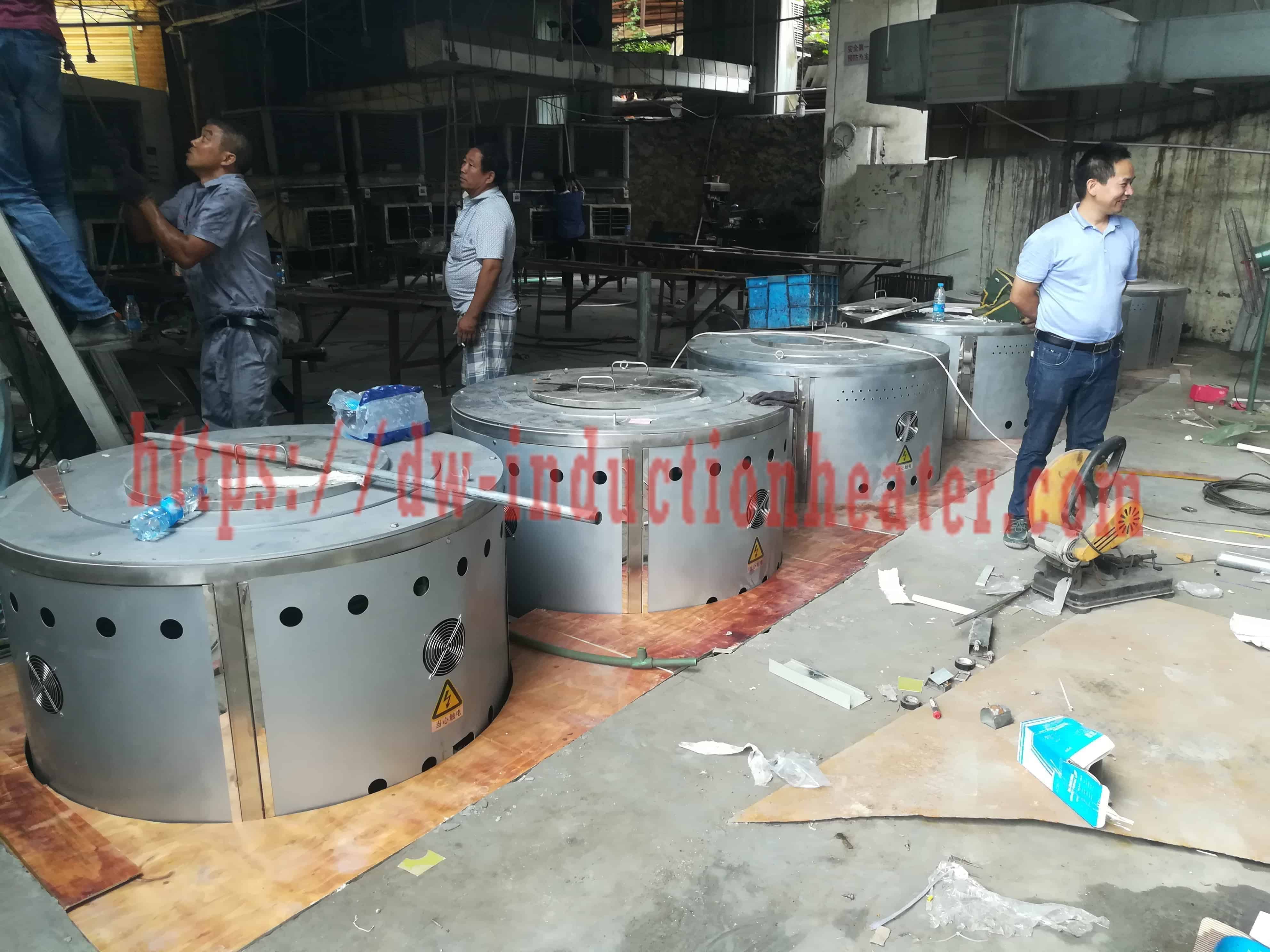
Once the melt is made, the published process documentation for aluminium recycling runs from the charge through to the finished ingot: see the Aluminium scraps recycling melting process.
Common Problems and Solutions
The first six rows below are the published HLQ common-problems table. The last three rows are consolidated from the published maintenance, safety and troubleshooting guidance on the HLQ hydraulic tilting induction furnace and aluminum melting pages, and are grouped here for convenience rather than as a single published table.
| Problem | Likely cause | Solution |
|---|---|---|
| Violent eruption when charging | Wet, oily or sealed scrap | Charge only clean, dry material; remove sealed cavities |
| Melting slower than expected | Power too low for the batch, or poor charge packing | Check power against the capacity table; improve charge density |
| Short lining life | Wrong lining chemistry for the metal or slag | Choose an acidic, neutral or basic lining to suit the metal |
| Zinc loss and fume with brass | Overheating; zinc fuming | Control temperature; use fume extraction |
| Dross and burning loss with aluminium | Thin, dirty or coated scrap; high temperature | Clean and dry the charge; control the temperature; use flux |
| Water alarm or trip | Low flow or pressure, or blocked circuits | Check the cooling tower or chiller, water quality and filters |
| Oxidation loss is high | Excessive temperature, long holding time or poor slag coverage | Control temperature, reduce holding time and use proper flux or cover when needed |
| Pouring is unstable | Hydraulic system problem or poor ladle/furnace alignment | Inspect tilting mechanism, hydraulic system and pouring layout |
| Lining damaged during charging, risking molten metal leakage | Wrong refractory material, thermal shock or mechanical damage during charging | Select proper lining, preheat correctly and avoid dropping heavy charge onto lining |

Engineering Selection Guide
Selecting an induction melting oven should not be based only on the rated capacity. The published engineering guidance sets out nine confirmation factors — metal type, batch capacity, melting time, daily production, power supply, tilting, cooling, layout and continuous casting — and the table below reproduces them.
| Selection factor | What to confirm | Engineering recommendation |
|---|---|---|
| Metal type | Steel, cast iron, aluminum, copper, brass or alloy | Choose lining, crucible and power density according to metal properties |
| Batch capacity | Required kg per batch | Select furnace capacity with reasonable margin for production demand |
| Melting time | Required minutes per batch | Higher power reduces melting time but increases electrical demand |
| Daily production | Tons per shift or tons per day | Calculate furnace number and power based on actual casting schedule |
| Power supply | Plant voltage, transformer capacity, cable size | Confirm electrical capacity before ordering |
| Tilting | Manual, mechanical or hydraulic | Hydraulic for medium and large furnaces |
| Cooling | Water flow, pressure, temperature and quality | Closed-loop cooling tower or industrial chiller |
| Layout | Charging area, crane, ladle path, mould area | Plan the layout before fixing furnace dimensions |
| Continuous casting | Rod, bar, strip or wire output | See the small induction melting and continuous casting furnace |
Two aluminium-specific factors sit on top of this published list. The charge condition, coating and paint residue and moisture have to be confirmed, because the published common-problems guidance for aluminium is that thin, dirty or coated scrap, together with high temperature, is the main cause of dross and burning loss, and the remedy given is to clean and dry the charge, control the temperature and use flux. And the alloy has to be confirmed against the lining, because the lining is a consumable whose life depends on the metal and the slag it sees.
Two numbers are worth carrying through this guide. The published theoretical heat for aluminium is about 0.30 kWh/kg to 720 °C, so a 300 kg aluminium heat carries a theoretical requirement of roughly 90 kWh before any furnace loss. At the published 20 % – 30 % saving against gas and oil melting, that gap is where the operating-cost argument for an induction oven comes from — and it is also why the specification of the power supply, the coil and the cooling circuit is not a detail but the whole economics.
For the published route from an aluminium melt to a cast ingot, see the aluminium recycling furnace product page.

None of the nine confirmation items in the table above can be settled on paper alone, which is why the layout question is the one that most often moves a delivery date. The published layout concept below shows the arrangement the published component list implies: the charge and returns area, the melting bay with the furnace and its fume extraction hood, the ladle station, and the moulding and cooling area, served from below by the power supply, the capacitor cabinet, the control panel, the cooling water plant and the plant services.

Advantages and Limitations
| Advantages | Limitations |
|---|---|
| Fast, clean, uniform melting; heat is produced in the charge | Needs a large electrical supply for big furnaces |
| Electromagnetic stirring mixes the alloy | The refractory lining is a consumable and must suit the metal |
| No burner or combustion gas in contact with the melt | Continuous cooling water is required |
| Temperature set by the power supply; easy to control | Charge must be dry and clean for safety |
| Scalable from 0.5 kg to 5,000 kg | Highly volatile alloys (brass, Be-Cu) need fume extraction |
| Published 20 % – 30 % power saving against gas and oil melting (the product pages state 20 % – 40 % against a diesel workshop furnace) | Dross and burning loss still occur with thin, dirty or coated aluminium scrap |
| Electricity-powered: no air pollution, no dust and little noise | The 1800 °C figure is a furnace rating, not an aluminium operating setpoint |
| Published 100 % duty cycle for 24 hours work | Published kilogram capacities are listed batch capacities, not hourly production rates |
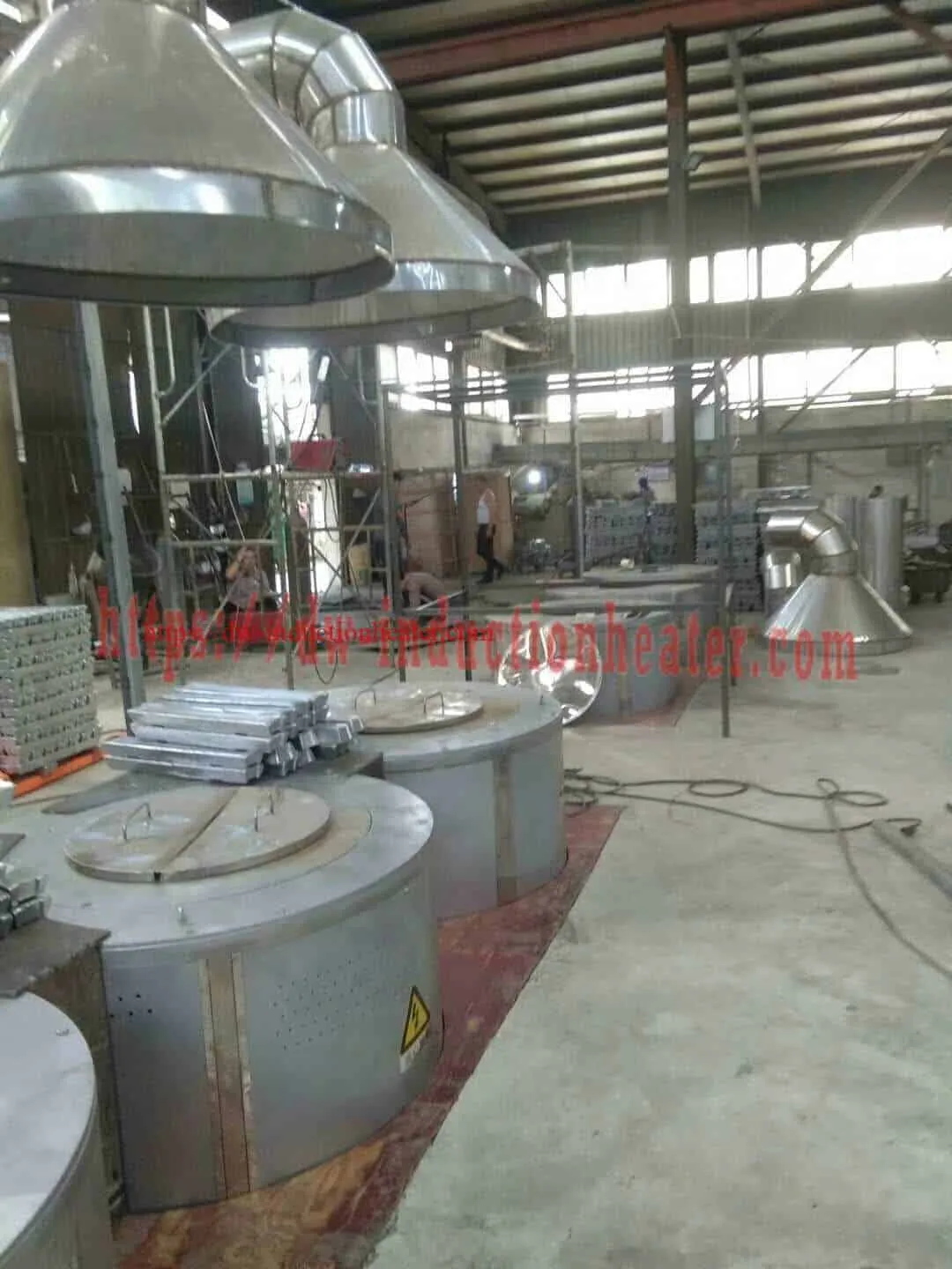
The six advantages published in the HLQ induction melting furnace manual state the same case in the manufacturer’s own words: high efficiency, because the induction power transfers heat to the furnace in a short time; energy saving of 20 % to 30 % against traditional melting with gas and oil; easy and safe to use, with an all-round indicator lights controller; stability in use, because the products are tested at every level; environmentally friendly operation, being electricity-powered with no air pollution, no dust and little noise; and easy installation, being portable and saving room.
Why Choose HLQ?
HLQ Induction Equipment Co., Ltd, with its branch Quanzhou Shuimu Induction Equipment Co., Ltd, is located in the Quanzhou National High & New Technology and Industrial Development Zone at No.906 Zhaolian Industrial District, Beifeng Town, Quanzhou City, Fujian Province, China. The published company statement records 25 years of experience in the research, design and production of high frequency and medium frequency induction heating machines, with leading products including IGBT medium frequency induction heating equipment, IGBT super audio induction heating equipment, CNC quenching machine tool, IGBT medium frequency induction melting furnace, KGPS medium frequency induction melting furnace, and open type and closed water cooling towers.
| Strength | What it means for you |
|---|---|
| Direct manufacturer, 25 years of production experience | One supplier for the power supply, the furnace body, the crucible and the cooling circuit, instead of a matched set of parts from several vendors |
| Complete published capacity range | From the DW-MF small-batch series at 3 kg of aluminium through the SMJD series at 150 – 1,200 kg to the published 5 – 5,000 kg plant range |
| IGBT and SCR/KGPS power supplies | Power supply matched to furnace size: IGBT for small and medium furnaces, SCR/KGPS for large melting capacity |
| Full system supply | Induction heating generator, melting furnace, compensation capacitor, cooling and control supplied as one specification |
| Quality control to TQM | A QC person inspects machinery production; every machine is tested and debugged before shipment, with photos and video on request |
| Test machine running before shipment | The published statement is that the technical staff test the machine running before it leaves |
| Warranty | The heating power is warranted for 12 months from the date the contract is signed |
| Packing | Film layer for waterproof, then a paper box, then a wooden case, with foam wrapped around the machine for shockproof |
| Shipping | Free delivery to the buyer’s shipper in China, or direct delivery to any main port of China |
| Storage conditions | Clean, dry environment, -20 °C to 60 °C, humidity 0 % – 95 % with no dew, away from corrosive gases and liquids |
| After-sales service | Engineers are sent to the customer’s workshop for installation, debugging and training until the machine is in normal production |
6 Core FAQs
1. Is an aluminum melting oven the same machine as an aluminum melting furnace?
In most published cases, yes. Both names refer to a coreless electric induction crucible furnace that melts metal in a crucible and pours it into a ladle or moulds. The distinction that does matter is between an induction furnace and an induction heater: the furnace melts metal in a crucible, the heater heats a formed part in a coil, and one does not substitute for the other. The published HLQ range covers three aluminium melting families — DW-MF for small batches, SMJD for production batches, and the hydraulic tilting furnace range for foundry scale.
2. How much electricity does an induction melting oven use compared with a gas or diesel furnace?
The published figure in the HLQ induction melting furnace manual is a 20 % – 30 % power saving against traditional melting methods using gas and oil. The theoretical heat requirement published for aluminium is approximately 0.30 kWh/kg to melt and hold the metal at 720 °C, before coil, crucible, lining and radiation losses. The published electrical demand on the SMJD series runs from 60 kW to 200 kW against aluminium capacities of 150 kg to 1,200 kg per heat, on a 3-phase 380 V, 50 – 60 Hz supply.
3. What aluminium capacity is published, and are those figures production rates?
The published aluminium capacity of the SMJD series runs from 150 kg per heat on the SMJD-480 up to 1,200 kg per heat on the SMJD-3100, across 13 published models with input power from 60 kW to 200 kW. These are listed batch capacities. They do not establish hourly production rates, melting times, metal recovery or specific electricity consumption, and they should not be quoted as if they did. The DW-MF series is published separately for small batches, from 3 kg of aluminium on the DW-MF-15 up to 75 kg on the DW-MF-160, with a published melting time of 30 – 50 minutes per batch.
4. Which crucible and lining should an aluminium melting oven use?
The published lining and crucible for aluminium is graphite, SiC-graphite or high-alumina, with an integral polycrystalline mullite fibre furnace lining rated above 1200 °C. The lining is a consumable and its life depends on the alloy and on the slag it sees, which is why the published guidance is to choose lining chemistry to suit the metal and to inspect the lining for cracks, erosion and wear after each shift.
5. Can the same furnace handle aluminium scrap, pop cans and alloy returns?
The published SMJD aluminium capacity column lists aluminum, aluminum alloy, aluminum scrap, aluminum slag and pop can, so the furnace is specified for mixed and contaminated feed as well as clean charge. The process consequences are real, though: coating and paint residue does not melt with the metal but floats to the surface as dross, which is skimmed off with a steel ladle and processed separately, and the published common-problems guidance is that thin, dirty or coated scrap, together with high temperature, is the main cause of dross and burning loss with aluminium.
6. What has to be confirmed before ordering?
Confirm the metal and alloy, the batch weight per heat, the required melting time and the daily production, then the plant electrical capacity — voltage, transformer capacity and cable size — the cooling water flow, pressure and quality, the tilting method, the lining for the metal and slag, and the layout of the charging area, crane, ladle path and mould area. The published packing, shipping and storage terms, the 12-month heating power warranty and the published installation, debugging and training service are all part of the supply, and each of them is easier to agree before the order than after it.