



5–5000kg Copper Melting Induction Furnace for Copper Alloy Casting
5–5000kg Copper Melting Induction Furnace for Copper Alloy Casting | Engineering Selection Guide
Table of Contents
- Product Summary
- Quick Answer
- What Is This Product?
- Key Applications
- Suitable Materials
- Working Principle
- Technical Specifications
- Recommended Model Selection
- Process Workflow
- Coil and Fixture Design
- Control System and Automation
- Common Problems and Solutions
- Engineering Selection Guide
- Advantages
- Limitations
- Why Choose HLQ Induction Equipment?
- FAQ
The 5–5000kg copper melting induction furnace is a scalable, IGBT-powered electromagnetic melting system engineered to melt pure copper, brass, bronze, cupronickel, and all major copper alloy families across a continuous capacity range from 5 kg laboratory units to 5,000 kg industrial production furnaces. Deployed in copper foundries, die casting plants, wire rod mills, jewelry workshops, and copper scrap recycling facilities, this furnace range solves the most critical buyer challenges: high energy costs, excessive oxidation and metal loss, inconsistent alloy chemistry, slow melting cycles, and the inability to scale production without changing technology platforms. A single product family covers every copper melting requirement from bench-top R&D to full-scale continuous casting.
Quick Answer
The 5–5000kg copper melting induction furnace is a coreless, medium-frequency IGBT induction melting system that covers the complete industrial capacity spectrum for copper and copper alloy melting — from 5 kg precision casting cells to 5,000 kg high-throughput foundry and recycling operations. It is best suited for any facility that requires clean, energy-efficient, precisely temperature-controlled copper melting with minimal oxidation loss, fast cycle times, and the flexibility to process multiple alloy grades. With power ratings from 15 kW to 3,500 kW and operating frequencies from 250 Hz to 8,000 Hz, the correct model within this range can be matched to virtually any copper melting application.
What Is This Product?
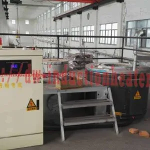
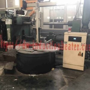
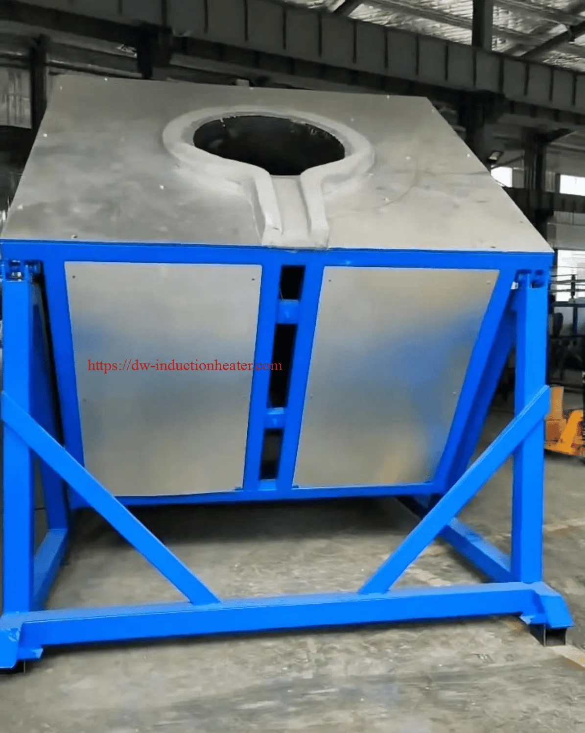
The 5–5000kg copper melting induction furnace range encompasses a family of coreless induction melting systems that share a common operating principle — electromagnetic induction heating — but are individually engineered for their specific capacity class. Each furnace in the range consists of three core subsystems: an IGBT solid-state power supply unit, a water-cooled copper induction coil assembly, and a refractory-lined steel crucible shell with hydraulic tilting mechanism.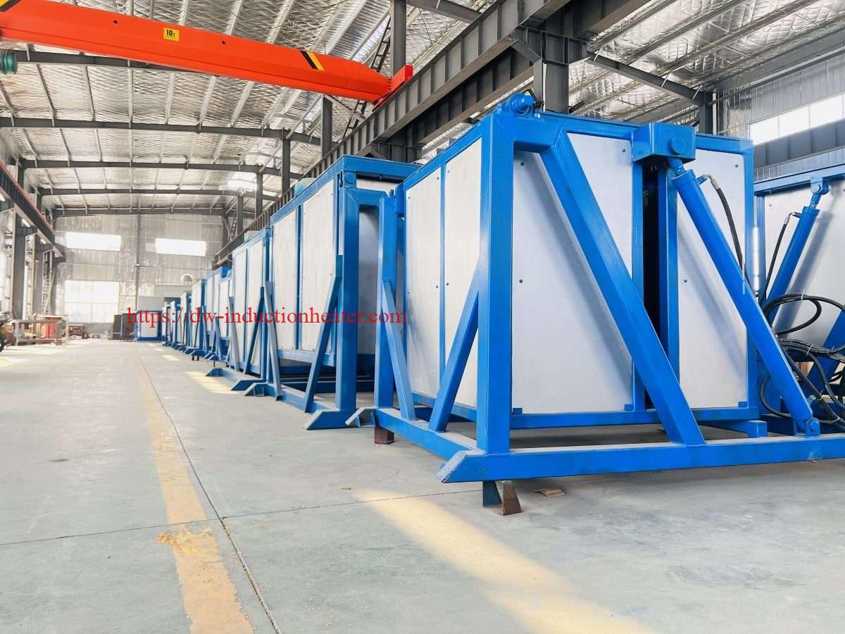
What makes this capacity range particularly significant from an engineering standpoint is that copper presents fundamentally different electromagnetic challenges at different scales. A 5 kg furnace melting jewelry-grade copper requires a high-frequency (4,000–8,000 Hz) coil with tight coupling and rapid thermal response. A 5,000 kg furnace melting copper scrap for continuous casting requires a low-frequency (250–500 Hz) system with deep electromagnetic penetration, strong stirring, and sustained high-power operation over multi-hour cycles. The 5–5000kg range is not a single product stretched across capacities — it is a family of purpose-engineered systems sharing a common technology platform.
The following table provides a high-level overview of the three capacity tiers within the 5–5000kg range, their primary characteristics, and their target markets.
| Capacity Tier | Capacity Range | Power Range | Frequency Range | Primary Market | Typical Cycle Time |
|---|---|---|---|---|---|
| Small / Laboratory | 5 – 100 kg | 15 – 75 kW | 2,000 – 8,000 Hz | Jewelry, R&D, art casting, small foundry | 15 – 45 min/heat |
| Medium / Workshop | 100 – 1,000 kg | 75 – 750 kW | 500 – 2,500 Hz | Brass/bronze foundry, die casting, valve production | 45 – 120 min/heat |
| Large / Industrial | 1,000 – 5,000 kg | 750 – 3,500 kW | 250 – 1,000 Hz | Copper recycling, wire rod, continuous casting, anode production | 90 – 240 min/heat |
Key Applications
The 5–5000kg range covers every major copper melting application in modern industry. The table below maps each application to the appropriate capacity tier, alloy type, and key process requirement.
| Application | Capacity Tier | Primary Alloy | Key Process Requirement | Industry Sector |
|---|---|---|---|---|
| Jewelry and art casting | 5 – 30 kg | Pure Cu, Cu-Au alloys | Precise temperature, small batch, clean melt | Jewelry / Art |
| Metallurgical R&D / alloy development | 5 – 100 kg | All Cu alloys | Flexible alloy switching, accurate composition control | Research / Laboratory |
| Investment casting (precision parts) | 50 – 300 kg | Bronze, Al-bronze, Cu-Ni | High melt cleanliness, temperature uniformity | Aerospace / Marine / Defense |
| Brass valve and fitting production | 200 – 1,000 kg | C36000, C28000, C37700 | Zinc loss control, fast cycle, consistent chemistry | Plumbing / HVAC / Industrial |
| Bronze bearing and bushing casting | 100 – 500 kg | C93200, C90500, C95400 | Tin/aluminum distribution, low porosity | Industrial machinery |
| Copper scrap recycling | 500 – 5,000 kg | No.1/No.2 Cu, mixed scrap | High throughput, low melt loss, scrap flexibility | Secondary copper / Recycling |
| Copper wire rod and strip casting | 2,000 – 5,000 kg | Cu-ETP (C11000) | Continuous supply, low oxygen, high purity | Electrical / Wire & Cable |
| Copper anode production | 3,000 – 5,000 kg | FRHC copper | Precise temperature for anode casting, low slag | Copper refining |
| Beryllium copper / specialty alloys | 50 – 500 kg | CuBe2, CuCr, CuZr | Sealed atmosphere, toxicological safety, tight temp control | Electronics / Aerospace |
Suitable Materials
The 5–5000kg induction furnace range is designed to process the complete spectrum of copper-based materials. Material properties directly influence furnace sizing, frequency selection, refractory choice, and process parameters. The table below provides a comprehensive material reference guide.
| Material | Standard Grade | Melting Range (°C) | Density (kg/dm³) | Recommended Lining | Special Handling |
|---|---|---|---|---|---|
| Electrolytic Tough Pitch Copper | Cu-ETP (C11000) | 1,083 – 1,100 | 8.96 | Magnesia (MgO ≥ 90%) | Oxygen control; charcoal cover |
| Oxygen-Free Copper | Cu-OF (C10200) | 1,083 – 1,095 | 8.94 | Magnesia or Alumina-Magnesia | Inert gas blanket mandatory |
| Oxygen-Free Electronic Copper | Cu-OFE (C10100) | 1,083 – 1,090 | 8.94 | High-purity Magnesia | Sealed atmosphere; ultra-dry gas |
| Cartridge Brass (70/30) | C26000 | 915 – 955 | 8.53 | Silica (SiO₂ ≥ 97%) | Zinc fuming; fume extraction required |
| Muntz Metal (60/40 Brass) | C28000 | 900 – 940 | 8.39 | Silica | Higher zinc loss; temp control critical |
| Free-Cutting Brass | C36000 | 885 – 900 | 8.50 | Silica or Alumina-Silica | Lead content; ventilation required |
| Tin Bronze (Gunmetal) | C90300, C90500 | 850 – 1,000 | 8.80 | Silica or Alumina | Phosphorus deoxidation standard |
| Bearing Bronze | C93200 (SAE 660) | 854 – 1,000 | 8.93 | Silica | Lead segregation risk; stir well |
| Aluminum Bronze | C95400, C95500 | 1,030 – 1,100 | 7.45 | Alumina (Al₂O₃ ≥ 90%) | Al₂O₃ inclusion control; careful skimming |
| Cupronickel 90/10 | C70600 | 1,100 – 1,145 | 8.94 | Magnesia or Chrome-Magnesia | High temp; nickel addition sequence critical |
| Cupronickel 70/30 | C71500 | 1,170 – 1,240 | 8.95 | Chrome-Magnesia or Spinel | Highest temp in Cu range; robust lining essential |
| Beryllium Copper | C17200 (CuBe2) | 870 – 980 | 8.25 | High-purity Alumina | BeO toxic fume; sealed enclosure mandatory |
| Silicon Bronze | C65500 | 970 – 1,025 | 8.53 | Silica or Alumina | Good fluidity; low gas absorption |
| Copper Scrap (Mixed) | No.1 / No.2 Copper | Varies | Varies (bulk 2–5 kg/dm³) | Match to dominant alloy | Pre-sort; pre-dry; higher dross management |
Working Principle
The operating principle is consistent across all capacity classes in the 5–5000kg range, though the engineering parameters — frequency, coil geometry, power density, and skin depth — are scaled and optimized for each capacity tier. The following table summarizes the key physics at each stage of the induction melting process and how they apply specifically to copper.
| Stage | Physical Mechanism | Copper-Specific Consideration | Engineering Parameter |
|---|---|---|---|
| 1. Power Conversion | 3-phase AC → DC → Medium-frequency AC via IGBT inverter | High power density required due to copper’s high melting point (1,083°C) and density (8.96 kg/dm³) | IGBT efficiency: 93–97%; frequency: 250–8,000 Hz |
| 2. Resonant Circuit | LC resonant tank (coil + capacitor bank) amplifies coil current 5–15× | Copper’s high conductivity requires careful impedance matching to maintain resonance across temperature range | Power factor ≥ 0.95 with auto-compensation |
| 3. Magnetic Field Generation | Alternating current in coil creates oscillating magnetic field (B-field) in crucible bore | Field must penetrate solid copper charge efficiently; copper is non-magnetic (μᵣ ≈ 1) | Field intensity: 50–500 kA/m depending on power and coil design |
| 4. Eddy Current Induction | B-field induces circulating eddy currents in copper charge surface layer | Copper’s very high conductivity (58 MS/m at 20°C) means shallow skin depth; solid copper couples less efficiently than molten copper | Skin depth (solid Cu, 1,000 Hz): ~2.1 mm; (molten Cu, 1,000 Hz): ~12 mm |
| 5. Joule Heating | Eddy currents × electrical resistance → heat (Q = I²Rt) | As copper heats, resistivity increases ~6×, improving coupling efficiency progressively through the melt cycle | Specific energy: 380–520 kWh/t depending on alloy and charge form |
| 6. Electromagnetic Stirring | Lorentz forces (J × B) drive convective circulation in molten bath | Strong stirring promotes alloy homogeneity, inclusion flotation, and temperature uniformity; critical for brass zinc distribution | Stirring velocity: 0.1–0.5 m/s in molten bath; controllable via power and frequency |
| 7. Temperature Control | PID feedback from Type B thermocouple modulates IGBT power output | Copper’s high thermal conductivity (385 W/m·K solid) aids temperature uniformity; Type B thermocouple required for 1,083–1,300°C range | Temperature accuracy: ±5°C in holding mode |
The following diagram illustrates the skin depth behavior of copper across the operating temperature range at different frequencies — a critical design parameter for coil engineers.
| Frequency (Hz) | Skin Depth — Solid Cu at 20°C (mm) | Skin Depth — Solid Cu at 800°C (mm) | Skin Depth — Molten Cu at 1,100°C (mm) | Best Suited Capacity |
|---|---|---|---|---|
| 8,000 | 0.74 | 2.1 | 4.2 | 5 – 20 kg |
| 4,000 | 1.05 | 3.0 | 5.9 | 20 – 100 kg |
| 2,000 | 1.48 | 4.2 | 8.4 | 100 – 300 kg |
| 1,000 | 2.10 | 5.9 | 11.8 | 300 – 800 kg |
| 500 | 2.96 | 8.4 | 16.7 | 800 – 2,000 kg |
| 250 | 4.19 | 11.9 | 23.6 | 2,000 – 5,000 kg |
Technical Specifications
The following master specification table covers the complete 5–5000kg capacity range, organized by capacity class. All values represent standard HLQ production specifications; custom configurations are available.
| Parameter | 5–50 kg (Small) | 50–500 kg (Medium) | 500–2,000 kg (Large) | 2,000–5,000 kg (Industrial) |
|---|---|---|---|---|
| Rated Power | 15 – 50 kW | 50 – 400 kW | 400 – 1,500 kW | 1,500 – 3,500 kW |
| Operating Frequency | 2,000 – 8,000 Hz | 500 – 2,500 Hz | 250 – 1,000 Hz | 150 – 500 Hz |
| Input Voltage | 3×380V / 415V | 3×380V / 415V / 660V | 3×380V / 660V / 6kV | 6kV / 10kV |
| Power Factor (cos φ) | ≥ 0.93 | ≥ 0.95 | ≥ 0.95 | ≥ 0.96 |
| Electrical Efficiency | 90 – 93% | 93 – 95% | 94 – 96% | 95 – 97% |
| Melting Rate (Pure Cu) | 10 – 50 kg/h | 50 – 350 kg/h | 350 – 1,200 kg/h | 1,200 – 3,500 kg/h |
| Specific Energy (Cu ingot) | 420 – 520 kWh/t | 400 – 480 kWh/t | 385 – 450 kWh/t | 380 – 430 kWh/t |
| Operating Temperature | Up to 1,350°C | Up to 1,300°C | Up to 1,280°C | Up to 1,250°C |
| Temperature Accuracy | ±8°C | ±5°C | ±5°C | ±3°C |
| Lining Material | Alumina / Magnesia | Silica / Alumina / Magnesia | Magnesia / Alumina | Magnesia / Chrome-Magnesia |
| Lining Life | 80 – 200 heats | 150 – 350 heats | 200 – 400 heats | 150 – 300 heats |
| Tilting Mechanism | Manual / Small hydraulic | Hydraulic | Hydraulic (dual cylinder) | Hydraulic (heavy duty) |
| Cooling Water Flow | 5 – 20 m³/h | 20 – 80 m³/h | 80 – 200 m³/h | 200 – 500 m³/h |
| Cooling Water Pressure | 0.2 – 0.3 MPa | 0.2 – 0.4 MPa | 0.3 – 0.4 MPa | 0.3 – 0.5 MPa |
| Control Interface | Digital panel / 7″ HMI | PLC + 10″ HMI | PLC + 12″ HMI + SCADA | PLC + 15″ HMI + MES/SCADA |
| THD (with filter) | < 8% | < 5% | < 5% | < 3% |
| Protection Class | IP23 | IP23 / IP54 optional | IP54 | IP54 |
| Lining Wear Monitor | Basic earth leakage | Earth leakage + alarm | Multi-level alarm system | Continuous resistance monitoring |
Recommended Model Selection
The following table provides specific model selection guidance for the most common copper melting applications across the 5–5000kg range. Use this as the primary engineering reference for initial furnace specification.
| Application | Material | Recommended Capacity | Recommended Power | Frequency | Key Feature |
|---|---|---|---|---|---|
| Jewelry / art casting | Pure Cu, Cu-Au | 5 – 15 kg | 15 – 25 kW | 4,000 – 8,000 Hz | Compact; tilt pour; inert gas option |
| Laboratory / R&D | All Cu alloys | 10 – 100 kg | 25 – 75 kW | 2,000 – 4,000 Hz | Wide alloy flexibility; recipe storage |
| Small brass foundry | C26000, C36000 | 100 – 300 kg | 75 – 200 kW | 1,000 – 2,500 Hz | Zinc loss control; fume extraction |
| Bronze investment casting | C90300, C95400 | 50 – 300 kg | 50 – 200 kW | 1,000 – 2,000 Hz | High melt cleanliness; tight temp control |
| Medium brass/bronze foundry | C28000, C90500 | 300 – 1,000 kg | 200 – 700 kW | 500 – 1,500 Hz | Hydraulic tilt; PLC control; batch production |
| Cupronickel casting | C70600, C71500 | 200 – 800 kg | 150 – 600 kW | 500 – 1,500 Hz | High-temp lining; robust cooling system |
| Copper scrap recycling | No.1/No.2 Cu, mixed | 500 – 3,000 kg | 400 – 2,000 kW | 250 – 1,000 Hz | High throughput; scrap flexibility; low melt loss |
| Beryllium copper | C17200, C17500 | 50 – 500 kg | 50 – 350 kW | 1,000 – 3,000 Hz | Sealed enclosure; full exhaust filtration |
| Copper wire rod / continuous casting | Cu-ETP (C11000) | 2,000 – 5,000 kg | 1,500 – 3,500 kW | 150 – 400 Hz | Continuous operation; low oxygen; MES integration |
| Copper anode casting | FRHC copper | 3,000 – 5,000 kg | 2,000 – 3,500 kW | 150 – 350 Hz | Precise pour control; high-duty lining |
Process Workflow
The melting workflow varies by capacity tier. The table below summarizes the key process steps and the specific requirements at each tier, followed by a detailed step-by-step description for the medium-capacity (100–1,000 kg) class as the most broadly applicable reference.
| Process Step | 5–50 kg (Small) | 100–1,000 kg (Medium) | 1,000–5,000 kg (Industrial) |
|---|---|---|---|
| 1. Pre-heat / Inspection | Visual check; 15 min pre-heat at 30% power | Lining thickness check; 30–45 min pre-heat cycle | Full lining inspection; 60–90 min staged pre-heat protocol |
| 2. Charge Preparation | Weigh ingots/scrap; inspect for contamination | Sort by alloy; weigh; pre-dry if required | Automated charge weighing; scrap pre-dryer integration |
| 3. Initial Charge Loading | Load dense ingots first; manual loading | Dense material first; charging crane or fork | Charging crane with weigh hopper; automated sequence |
| 4. Power Ramp-Up | 30% → 100% over 5–10 min | 30% → 100% over 15–20 min | Staged ramp: 20% → 50% → 100% over 30–45 min |
| 5. Progressive Charge Addition | Add remaining charge as first batch melts | Add scrap/returns in 2–4 increments with flux | Continuous charge addition via automated system |
| 6. Flux Application | Charcoal or borax cover; manual application | Proprietary copper flux; applied after each charge | Automated flux dosing system |
| 7. Alloying | Manual addition of master alloys | Weighed master alloy additions; stir and sample | Automated alloy addition with OES feedback loop |
| 8. Degassing / Deoxidation | P-Cu addition; manual lance purge | P-Cu addition; rotary degassing or gas lance | Automated degassing unit; density index monitoring |
| 9. Dross Removal | Manual skimming | Manual or mechanical skimming | Mechanical skimmer; dross recovery system |
| 10. Temperature Verification | Immersion thermocouple; manual check | Type B thermocouple; HMI display | Dual thermocouple + pyrometer; automated go/no-go |
| 11. Composition Verification | Sample for lab analysis | OES spectrometer sample | In-line OES with automated adjustment |
| 12. Pouring | Manual tilt; ladle or direct mold pour | Hydraulic tilt; controlled pour rate | Automated tilt with casting machine interface |
Coil and Fixture Design
Coil design parameters vary significantly across the 5–5000kg capacity range. The following table provides the key coil engineering parameters for each capacity tier, serving as a design reference for application engineers.
| Design Parameter | 5–50 kg | 50–500 kg | 500–2,000 kg | 2,000–5,000 kg |
|---|---|---|---|---|
| Coil Conductor Cross-Section | 10×10 mm to 15×20 mm | 20×25 mm to 30×40 mm | 35×50 mm to 50×70 mm | 60×80 mm to 80×100 mm |
| Number of Turns | 6 – 12 turns | 8 – 14 turns | 6 – 10 turns | 4 – 8 turns |
| Coil Height/Diameter Ratio | 0.9 – 1.3 | 0.85 – 1.2 | 0.8 – 1.1 | 0.75 – 1.0 |
| Current Density in Conductor | 15 – 25 A/mm² | 18 – 30 A/mm² | 20 – 35 A/mm² | 25 – 40 A/mm² |
| Cooling Water Flow (per coil) | 3 – 8 L/min | 8 – 25 L/min | 25 – 80 L/min | 80 – 200 L/min |
| Coil-to-Lining Gap | 8 – 15 mm | 12 – 20 mm | 15 – 25 mm | 20 – 35 mm |
| Magnetic Yoke Coverage | 60 – 70% of coil height | 65 – 75% of coil height | 70 – 80% of coil height | 75 – 85% of coil height |
| Lining Thickness | 40 – 70 mm | 70 – 120 mm | 120 – 180 mm | 180 – 250 mm |
| Coil Insulation Rating | Class H (180°C) | Class H (180°C) | Class C (220°C) | Class C (220°C) |
The refractory lining selection matrix below provides alloy-specific guidance — the most critical coil and fixture design decision for copper melting applications.
| Alloy Family | Recommended Lining | Al₂O₃ or MgO Content | Sintering Temperature (°C) | Expected Life (heats) | Primary Failure Mode |
|---|---|---|---|---|---|
| Pure Copper (ETP, OF, OFE) | Magnesia (basic) | MgO ≥ 90% | 1,150 – 1,200 | 150 – 350 | Cu₂O chemical attack on silica |
| Brass (Cu-Zn) | Silica (acid) | SiO₂ ≥ 97% | 1,050 – 1,100 | 200 – 400 | Thermal cycling erosion |
| Tin Bronze (Cu-Sn) | Silica or Alumina | SiO₂ ≥ 95% or Al₂O₃ ≥ 85% | 1,050 – 1,150 | 180 – 350 | SnO₂ flux penetration |
| Aluminum Bronze (Cu-Al) | Alumina (neutral) | Al₂O₃ ≥ 90% | 1,100 – 1,200 | 120 – 280 | Al₂O₃ inclusion buildup |
| Cupronickel (Cu-Ni) | Chrome-Magnesia or Spinel | MgO ≥ 70% + Cr₂O₃ ≥ 15% | 1,200 – 1,280 | 100 – 250 | High-temperature creep and spalling |
| Beryllium Copper | High-purity Alumina | Al₂O₃ ≥ 95% | 1,100 – 1,150 | 100 – 200 | BeO reaction with basic linings |
Control System and Automation
The control system architecture scales with furnace capacity. The table below maps the control system features to each capacity tier, followed by a description of the key functional modules common to all tiers.
| Control Feature | 5–50 kg | 50–500 kg | 500–2,000 kg | 2,000–5,000 kg |
|---|---|---|---|---|
| Control Platform | Microcontroller + digital panel | PLC + 10″ color HMI | PLC + 12″ HMI + historian | Redundant PLC + 15″ HMI + SCADA/MES |
| Temperature Control | PID; Type K or B thermocouple | PID; Type B thermocouple; ±5°C | Dual PID; Type B + pyrometer; ±5°C | Advanced PID + model-based; ±3°C |
| Power Control | Manual knob; 0–100% | Digital; programmable ramp profiles | Programmable multi-stage ramp + hold | Fully automated power management |
| Lining Wear Monitor | Basic earth leakage relay | Resistance monitoring + alarm | Multi-level alarm (warning / critical) | Continuous real-time resistance trending |
| Cooling Water Monitor | Flow switch + temperature sensor | Flow meter + temp + pressure | Full flow/temp/pressure + auto-shutdown | Full monitoring + predictive alerts |
| Energy Metering | Basic kWh meter | Power analyzer; kWh per heat logging | Full power quality analyzer; cost reporting | Real-time energy dashboard + MES export |
| Recipe Management | Not available | Up to 20 alloy recipes | Up to 100 alloy recipes | Unlimited recipes; version control |
| Remote Monitoring | Not available | Optional Ethernet/VPN access | Standard remote access + alerts | Cloud-connected; real-time dashboards |
| Tilt Control | Manual lever | Hydraulic with speed control | Proportional hydraulic; programmable | Servo-hydraulic; casting machine interface |
| Harmonic Filter | Passive filter | Passive or active filter | Active harmonic filter standard | Active filter + power factor correction |
Common Problems and Solutions
The following troubleshooting table covers the most frequently encountered operational issues across the full 5–5000kg capacity range, with capacity-specific notes where relevant.
| Problem | Likely Cause | Solution | Capacity Note |
|---|---|---|---|
| Excessive Cu₂O dross (red oxide) | Inadequate flux cover; overheating; atmospheric O₂ exposure | Apply charcoal/borax flux immediately after each charge; reduce holding temp; use inert gas blanket for pure Cu grades | Most critical for large furnaces with long holding times |
| Hydrogen porosity in castings | Wet/oily scrap; moisture in flux; inadequate P-Cu deoxidation | Pre-dry all scrap and flux; add 0.02–0.05% P-Cu; purge with dry argon; perform density index test | All capacity tiers; more common with scrap charges |
| Zinc fuming (brass melting) | Temperature exceeding 1,050°C; prolonged holding | Reduce temperature to 950–1,000°C; minimize hold time; add zinc last; ensure fume extraction is operational | Medium and large furnaces with brass charges |
| Rapid lining erosion | Wrong lining chemistry for alloy; overheating; poor sintering; thermal shock | Select lining per alloy matrix table; follow sintering protocol; pre-heat charge; avoid temp above 1,250°C for extended periods | All tiers; most costly in large industrial furnaces |
| Furnace fails to start | Coil insulation fault; water flow alarm; IGBT failure; capacitor fault | Check coil insulation resistance (>1 MΩ); verify water flow; run IGBT diagnostic; check capacitor fuses | All tiers; small furnaces more susceptible to coil damage |
| Alloy out of specification | Incorrect charge calculation; volatile element loss; contaminated scrap | Recalculate charge weights; add volatile elements last; use certified scrap; calibrate OES spectrometer | All tiers; automated systems reduce risk in large furnaces |
| Earth leakage / lining breakthrough alarm | Lining eroded to critical thickness; metal penetration | Reduce power immediately; do not pour; schedule emergency relining; investigate root cause | Critical safety issue at all capacities; most dangerous in large furnaces |
| Cooling water overtemperature | Scale in coil tubing; pump failure; high ambient temp | Descale with citric acid; check pump; verify flow rate; increase cooling tower capacity | More common in large furnaces with high heat loads |
| Poor coupling / slow melting on cold start | Solid copper’s high conductivity → shallow skin depth → poor initial coupling | Start with dense, clean charge; use a starter block or maintain molten heel; apply power gradually; consider lower frequency for large solid charges | Most significant for large furnaces starting cold |
| Inconsistent alloy chemistry between heats | Variable scrap composition; manual alloy addition errors; sampling inconsistency | Implement certified scrap sorting; use automated alloy addition; standardize sampling procedure and OES calibration | Medium and large production furnaces |
Engineering Selection Guide
Use the following decision framework to identify the correct furnace model within the 5–5000kg range for a specific application. Work through each parameter in sequence.
| Selection Step | Parameter to Evaluate | Decision Criteria | Impact on Specification |
|---|---|---|---|
| Step 1 | Required throughput (t/h or t/shift) | Calculate net melting rate needed; apply 70% utilization factor | Determines minimum furnace capacity and power rating |
| Step 2 | Alloy family | Pure Cu / Brass / Bronze / Cu-Ni / Specialty | Determines lining material, atmosphere requirements, and temperature range |
| Step 3 | Charge form | Clean ingot / large returns / mixed scrap / fine scrap | Affects specific energy consumption, coupling efficiency, and charge preparation requirements |
| Step 4 | Batch vs. continuous operation | Batch casting vs. continuous casting line feed | Batch → coreless furnace; Continuous → channel furnace or coreless with molten heel |
| Step 5 | Atmosphere requirements | Open air / flux cover / inert gas blanket / sealed atmosphere | OFC and specialty alloys require sealed or semi-sealed furnace designs |
| Step 6 | Electrical infrastructure | Available supply voltage, capacity, and harmonic limits | Large furnaces (>750 kW) may require dedicated transformer and active harmonic filter |
| Step 7 | Automation level required | Manual / semi-automated / fully automated | Determines control system specification and integration requirements |
| Step 8 | Total cost of ownership | Capital + energy + metal loss + maintenance over 10 years | Induction typically achieves payback vs. gas-fired in 2–4 years at high utilization |
The following quick-reference power density guide helps engineers validate their power selection against industry benchmarks.
| Operation Type | Recommended Power Density (kW/t) | Notes |
|---|---|---|
| Rapid batch melting (ingot charge) | 450 – 600 kW/t | Maximum melting speed; shortest cycle time |
| Standard batch melting (mixed charge) | 350 – 450 kW/t | Balanced speed and energy efficiency |
| Scrap remelting (variable density) | 300 – 400 kW/t | Lower density scrap; longer effective cycle |
| Holding and temperature maintenance | 100 – 200 kW/t | Compensating for heat losses only |
| Continuous casting (melting + holding) | 250 – 350 kW/t | Steady-state supply to casting machine |
Advantages
| Advantage | Quantified Benefit | Most Significant For |
|---|---|---|
| High energy efficiency | 93–97% electrical efficiency vs. 40–60% for gas-fired | All capacity tiers; greatest absolute saving in large industrial furnaces |
| Low metal loss (melt loss) | 0.3–1.0% vs. 1.5–4.0% for gas-fired; saves $27–$270/t at $9,000/t Cu | High-volume copper scrap recycling and wire rod production |
| Superior melt quality | No combustion H₂ pickup; lower porosity; fewer inclusions | OFC production, investment casting, electrical conductor applications |
| Precise temperature control | ±3–8°C depending on capacity tier | Specialty alloys, OFC, continuous casting |
| Electromagnetic stirring | Natural bath circulation; no mechanical stirrers required | Brass (zinc distribution), bronze (tin distribution), alloy preparation |
| Fast melting cycles | 500 kg Cu in 60–90 min vs. 3–5 h in gas crucible furnace | Medium and large production foundries |
| Zero direct combustion emissions | No NOx, SOx, CO₂ at point of use | All tiers; critical for urban facilities and carbon-regulated operations |
| Alloy flexibility | Full alloy range from pure Cu to complex specialty alloys | Job shops, R&D labs, multi-product foundries |
| Scalable platform | 5 kg to 5,000 kg on same technology; consistent operation and training | Growing operations; multi-site manufacturers |
| Compact installation | No gas lines, flue stacks, or combustion air systems | Urban foundries, space-constrained facilities |
Limitations
| Limitation | Impact | Mitigation Strategy |
|---|---|---|
| Higher capital cost vs. gas-fired | 1.5–2.5× higher upfront investment | TCO analysis demonstrates 2–4 year payback; lease/financing options available |
| Poor cold-start coupling for solid copper | Reduced efficiency in first 15–20 min of cold start | |
| Poor cold-start coupling for solid copper | Reduced efficiency in first 15–20 min of cold start | Maintain molten heel in continuous operations; use dense ingot charge for cold starts; apply gradual power ramp |
| Refractory lining chemistry sensitivity | Wrong lining causes rapid failure and metal contamination | Strictly follow alloy-specific lining selection matrix; consult HLQ application engineers for non-standard alloys |
| Zinc fuming in brass melting | Zinc vapor loss; fume extraction infrastructure required | Control temperature below 1,050°C; add zinc last; install dedicated fume extraction above furnace |
| Electrical infrastructure requirements | Large furnaces require dedicated transformers and harmonic filters | Engage utility and electrical contractor early in project; budget for grid connection upgrades |
| Beryllium copper toxicological hazard | BeO fume is highly toxic; strict engineering controls mandatory | Sealed furnace enclosure; full exhaust filtration to HEPA standard; operator PPE and medical monitoring program |
| Skilled operation and maintenance required | Suboptimal operation leads to lining failures and poor melt quality | Invest in operator training; implement preventive maintenance program; use HLQ remote monitoring service |
| Water cooling infrastructure dependency | Cooling water failure causes immediate shutdown | Install closed-loop cooling with redundant pump; water quality monitoring; emergency backup cooling provision |
Why Choose HLQ Induction Equipment?
HLQ Induction Equipment is a specialist manufacturer and global engineering partner for induction melting systems, with a dedicated copper furnace product line covering the complete 5–5000kg capacity range. Our copper melting furnaces are installed and operating in foundries, recycling plants, wire rod mills, and research facilities across more than 60 countries.
The following table summarizes the key differentiators that set HLQ apart from generic induction furnace suppliers in the copper melting market.
| HLQ Differentiator | What It Means for the Customer | Applicable Capacity |
|---|---|---|
| FEA-optimized coil design for every model | Maximum electromagnetic efficiency and temperature uniformity from day one; no field tuning required | All tiers (5 – 5,000 kg) |
| Alloy-specific refractory engineering service | Correct lining selection and sintering protocol for every copper alloy family; eliminates premature lining failures | All tiers |
| IGBT technology with 95–97% efficiency | Lowest energy cost per tonne of molten copper in the industry; rapid ROI | Medium to industrial (100 – 5,000 kg) |
| Sealed atmosphere furnace designs | OFC and specialty alloy production capability; meets the most demanding purity specifications | Small to medium (5 – 500 kg) |
| Full-load factory acceptance testing | Every furnace verified at rated power before shipment; no commissioning surprises on site | All tiers |
| ISO 9001 manufacturing quality system | Consistent product quality; full traceability of all critical components | All tiers |
| 24/7 remote monitoring and diagnostics | Proactive fault detection; minimized unplanned downtime; remote firmware updates | Medium to industrial (100 – 5,000 kg) |
| Global spare parts availability | IGBT modules, capacitors, and refractory materials stocked for rapid dispatch worldwide | All tiers |
| On-site installation and operator training | Correct commissioning and trained operators from day one; faster ramp-up to full production | All tiers |
| TCO analysis service | Quantified financial case for investment; energy savings, metal loss reduction, and payback period calculated for your specific operation | All tiers |
HLQ’s engineering team is available for pre-sales application consultation, site surveys, and detailed technical proposals. Whether the requirement is a 15 kW jewelry casting furnace or a 3,500 kW continuous casting melting system, HLQ has the engineering depth and manufacturing capability to deliver a purpose-built solution.
FAQ
Q1: What capacity of copper melting induction furnace do I need for my foundry?
Start by calculating your required net melting throughput in kg per hour. Divide your total copper requirement per shift by the number of available melting hours, then apply a 70% utilization factor to account for charging, degassing, dross removal, and pouring time. For example, if your foundry needs 800 kg of molten copper per 8-hour shift, your net melting rate requirement is approximately 800 ÷ (8 × 0.70) = 143 kg/h. A 300 kg furnace with 200 kW installed power — delivering approximately 180–220 kg/h melting rate — would be the appropriate starting point, with one spare heat capacity as buffer.
Q2: What is the difference between a 5 kg and a 5,000 kg copper induction furnace beyond just size?
The differences go well beyond physical scale. A 5 kg furnace operates at 4,000–8,000 Hz with a small, tightly wound coil optimized for rapid heating of a small charge mass — it is essentially a precision instrument. A 5,000 kg furnace operates at 150–400 Hz with a large, heavy-section coil designed for deep electromagnetic penetration into a massive molten bath, sustained high-power operation over multi-hour cycles, and integration with automated casting lines. The control systems, refractory engineering, cooling infrastructure, electrical supply requirements, and operational procedures are all fundamentally different. This is why HLQ engineers each capacity tier as a distinct product rather than simply scaling a single design.
Q3: How do I control zinc loss when melting brass in an induction furnace?
Zinc loss in brass melting is primarily a function of melt temperature and holding time. The key control measures are: keep the melt temperature at the minimum required for good fluidity (typically 950–1,020°C for most brass alloys, never exceeding 1,050°C); minimize holding time at temperature; add zinc as the last alloying element, not at the start of the heat; maintain a covering flux layer (charcoal or proprietary copper flux) on the melt surface throughout the heat; and ensure the fume extraction system above the furnace is operational at all times. Induction furnaces inherently produce less zinc fuming than gas-fired furnaces because the melt surface temperature is lower and more uniform — but these procedural controls remain essential.
Q4: Can the 5–5000kg furnace range process copper scrap directly?
Yes, across all capacity tiers, but with important preparation requirements that vary by scrap type and furnace size. Clean, large-section scrap (copper pipe, bus bar offcuts, large castings) can be charged directly into any furnace in the range. Fine turnings, chips, and wire scrap should be pre-dried and, for furnaces above 500 kg, pre-briquetted or charged into an existing molten bath. Heavily contaminated scrap (oily, painted, or with non-copper inserts) must be cleaned and sorted before charging. Wet scrap must never be charged into a hot furnace due to the risk of steam explosion. For large-scale scrap recycling operations (1,000–5,000 kg tier), an integrated scrap pre-dryer and sorting system is strongly recommended to maximize throughput and minimize dross generation.
Q5: What thermocouple type should be used for copper melting temperature measurement?
Type B thermocouples (Platinum-6% Rhodium / Platinum-30% Rhodium) are the correct choice for copper melting applications. Type B thermocouples are rated for continuous service up to 1,700°C and provide accurate, stable readings across the full copper melting temperature range of 1,083–1,300°C. Type K thermocouples (rated to approximately 1,260°C) are marginally acceptable for brass and bronze melting at lower temperatures but degrade rapidly at pure copper melting temperatures and should not be used for sustained service above 1,100°C. All HLQ copper melting furnaces above 100 kg capacity are supplied with Type B immersion thermocouples as standard.
Q6: How long does a refractory lining last in a copper induction furnace, and what causes premature failure?
Under well-managed operating conditions, lining life ranges from 100 heats (cupronickel in chrome-magnesia lining) to 400 heats (brass in silica lining). The three most common causes of premature lining failure are: first, incorrect lining chemistry for the alloy being melted — particularly using silica linings for pure copper, which causes rapid Cu₂O chemical attack; second, thermal shock from charging cold, dense material into a hot furnace without adequate pre-heating; and third, operating at temperatures significantly above the design maximum for the lining material. Proper sintering of a new lining according to HLQ’s prescribed protocol is also critical — a poorly sintered lining may fail within 20–30 heats regardless of alloy compatibility.
Q7: What electrical supply is required for a 500 kg copper melting induction furnace?
A 500 kg copper melting furnace typically requires 300–400 kW of installed power. At 380V three-phase supply, this corresponds to a full-load current of approximately 455–608A, requiring a dedicated supply circuit with appropriate cable sizing and protection. A dedicated transformer of 400–500 kVA is recommended to isolate the furnace load from other sensitive equipment and to provide the voltage stability needed for optimal IGBT performance. An active or passive harmonic filter should be included to maintain THD below 5% at the point of common coupling. For installations in countries with 415V or 480V supply standards, HLQ supplies power supply units configured for the local voltage as standard.
Q8: What is the typical return on investment period when switching from a gas-fired furnace to an HLQ induction copper melting furnace?
Based on field data from HLQ customer installations, the typical payback period for switching from gas-fired to induction copper melting is 2–4 years, depending on production volume, local energy prices, and copper price. The three primary sources of financial return are: energy cost savings (30–45% reduction in energy cost per tonne); metal loss savings (1–3% reduction in melt loss, worth $90–$270 per tonne at $9,000/t copper); and reduced environmental compliance costs (elimination of flue gas treatment, combustion gas monitoring, and carbon levy exposure). At production volumes above 500 tonnes per year, the combined savings typically exceed $150,000–$400,000 annually, delivering payback well within the 4-year threshold that most industrial capital investment criteria require.