




Induction Brazing System for Tube Joint Manufacturing
Induction Brazing System for Tube Joint Manufacturing
Table of Contents
- Quick Answer
- Product Summary
- What Is This Product?
- Key Applications
- Suitable Materials
- Working Principle
- Key Technical Parameters
- Technical Specifications
- Engineering Selection Guide
- Recommended Model Selection
- Process Workflow
- Advantages
- Common Problems and Solutions
- Engineering Design Notes
- Industries Served
- Case Study / Typical Application
- FAQ
Quick Answer
An induction brazing system for tube joint manufacturing is an electromagnetic heating solution used to join copper, brass, stainless steel, carbon steel, aluminum, and mixed-metal tube assemblies by melting a suitable brazing filler metal at the joint interface without melting the base tube. It uses an induction power supply and a custom induction coil to heat the tube joint rapidly and locally, allowing the filler alloy to flow by capillary action into the tube-to-tube, tube-to-fitting, or tube-to-manifold clearance. Compared with flame brazing, induction brazing provides faster heating, better repeatability, cleaner operation, easier automation, lower operator dependence, and more stable leak-tight joints for HVAC, refrigeration, heat exchanger, automotive, hydraulic, pneumatic, and industrial tube manufacturing.
An Induction Brazing System for Tube Joint Manufacturing is a precision heating workstation designed to join tube assemblies using electromagnetic induction and controlled filler metal flow. It handles copper tubes, brass fittings, stainless steel tubes, carbon steel pipes, aluminum tubes, and selected dissimilar metal joints. The system usually includes an induction power supply, water-cooled brazing coil, fixture, cooling unit, temperature control, flux or protective atmosphere options, and manual or automatic feeding mechanisms. Main applications include HVAC tube joints, refrigeration pipelines, heat exchanger manifolds, automotive fluid tubes, hydraulic assemblies, and industrial piping components. Key buyer benefits include repeatable joint quality, fast cycle time, reduced open flame risk, lower labor variation, and easier integration into production lines.
What Is This Product?
An Induction Brazing System for Tube Joint Manufacturing is an industrial joining system used to produce strong, clean, and leak-tight tube joints. It is especially useful when a manufacturer needs repeatable brazing quality in medium or high-volume production. Instead of using a gas flame to heat the joint, the system uses electromagnetic induction to heat the tube or fitting locally. The heat melts the brazing filler metal, and the liquid filler flows into the joint clearance by capillary action. After cooling, the filler solidifies and forms a metallurgical bond between the joined parts.
Tube joint manufacturing often requires high consistency because the finished assembly may carry refrigerant, water, oil, hydraulic fluid, compressed air, fuel, steam, or process gas. A small leak, incomplete filler flow, overheated tube, or weak joint can cause production rejection or field failure. For this reason, tube brazing is not only a heating operation. It is a controlled manufacturing process involving material preparation, joint clearance, filler selection, flux control, coil design, heating cycle, cooling method, and inspection.
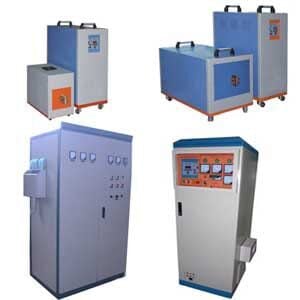
A typical induction brazing system includes an induction power supply, a brazing coil, a workpiece fixture, a cooling system, a foot switch or PLC controller, and optional automatic filler feeding. For advanced production lines, the system may include rotary indexing tables, robot loading, tube positioning fixtures, nitrogen protection, infrared temperature monitoring, barcode tracking, and quality data recording.
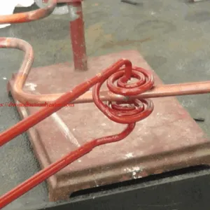
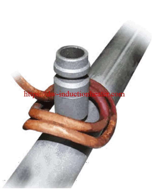
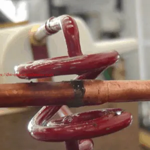
In engineering practice, the induction coil is one of the most important parts of the system. Tube joints are available in many shapes: straight tube couplings, elbow joints, T-joints, lap joints, socket joints, tube-to-block joints, tube-to-manifold joints, and tube-to-plate joints. Each joint may require a different coil shape to deliver uniform heating. A well-designed coil heats the joint area quickly and evenly while avoiding unnecessary heating of nearby components.
Key Applications
Induction brazing systems are widely used in tube joint manufacturing because tube assemblies often require clean, controlled, and repeatable joining. Compared with manual flame brazing, induction brazing is easier to standardize and automate, especially when the same tube joint must be produced thousands of times.
| Application | Typical Tube Joint | Common Material | Engineering Benefit |
|---|---|---|---|
| HVAC Tube Manufacturing | Copper tube to brass fitting, copper tube to distributor | Copper, brass | Fast, repeatable, clean tube joints with reduced operator variation |
| Refrigeration Systems | Capillary tube, compressor tube, condenser tube joint | Copper, copper alloy, steel | Reliable leak-tight brazed connections for refrigerant circuits |
| Heat Exchanger Production | Tube-to-header, tube-to-manifold, return bend joint | Copper, aluminum, stainless steel | Uniform local heating and high production repeatability |
| Automotive Tube Assemblies | Fuel tube, oil tube, EGR tube, brake or cooling tube joint | Steel, stainless steel, copper alloy | Suitable for automated fixtures and quality-controlled production |
| Hydraulic and Pneumatic Tubing | Tube-to-fitting, sleeve joint, threaded fitting joint | Carbon steel, stainless steel, brass | Strong mechanical joint and stable sealing performance |
| Industrial Process Tubing | Tube-to-flange, tube-to-collar, tube-to-block joint | Stainless steel, carbon steel, copper alloy | Controlled heating for special industrial assemblies |
| Medical and Instrument Tubing | Small diameter precision tube joints | Stainless steel, nickel alloy, copper alloy | Local heating with low distortion and repeatable quality |
Suitable Materials
Induction brazing is suitable for many conductive metals used in tube manufacturing. However, different materials require different filler metals, flux systems, temperatures, frequencies, coil designs, and heating cycles. A copper tube brazing process cannot be copied directly to stainless steel or aluminum tube brazing without modification.
| Material Combination | Suitability | Typical Filler Metal | Engineering Notes |
|---|---|---|---|
| Copper to Copper | Excellent | Phosphorus copper alloy, silver alloy | Common in HVAC and refrigeration; phosphorus copper may not require flux for copper-to-copper joints. |
| Copper to Brass | Excellent | Silver brazing alloy, phosphorus copper alloy | Flux is usually recommended for brass to prevent oxidation and improve wetting. |
| Copper to Steel | Good | Silver-based brazing alloy | Requires careful filler selection and flux control for dissimilar metal wetting. |
| Stainless Steel to Stainless Steel | Good | Silver alloy, nickel-based alloy | Surface cleanliness and flux/protective atmosphere are important. |
| Carbon Steel to Steel Fitting | Good | Copper-based or silver-based filler | Lower frequency may be used for thicker steel components. |
| Aluminum to Aluminum | Application-dependent | Aluminum-silicon filler | Requires precise temperature control because aluminum melting point is close to brazing temperature. |
| Brass to Brass | Good | Silver-based filler | Avoid overheating to prevent zinc loss and surface oxidation. |
| Nickel Alloy Tube Joints | Good with testing | Nickel-based or silver-based filler | Used in high-temperature or corrosion-resistant applications. |
Working Principle
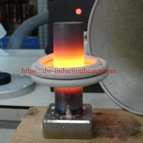
The working principle of an induction brazing system is based on electromagnetic induction. The induction power supply converts industrial AC power into high-frequency or medium-frequency current. This current flows through a copper induction coil. When the current passes through the coil, it creates an alternating magnetic field around the coil. When a conductive tube joint is placed in this magnetic field, eddy currents are induced in the metal. These eddy currents generate heat directly in the tube and fitting because of electrical resistance.
The generated heat raises the joint area to the brazing temperature. The brazing filler metal, which has a melting temperature lower than the base metal, melts and flows into the joint clearance. Correct joint clearance is essential. If the gap is too small, the filler may not enter the joint completely. If the gap is too large, capillary action becomes weak and the joint may have poor strength or leakage risk.
The base tube should not be melted during brazing. The goal is to heat both joined components enough for filler flow while keeping the base material solid. This requires a controlled power level, correct heating time, suitable coil geometry, and stable workpiece positioning. For production systems, the brazing cycle is often controlled by a timer, PLC, temperature feedback, or power recipe.
Compared with flame brazing, induction brazing can concentrate heat in a defined area. This reduces overheating of surrounding parts, improves cycle consistency, and allows the same heating profile to be repeated from part to part. For tube joint manufacturing, this repeatability is one of the main reasons manufacturers choose induction brazing.
Key Technical Parameters
| Parameter | Typical Range | Engineering Meaning |
|---|---|---|
| Power Rating | 5 kW – 120 kW | Determines heating speed, tube size capability, and production cycle time. |
| Frequency Range | 10 kHz – 500 kHz | High frequency is common for small and medium tube joints; lower frequency may be used for larger or thicker parts. |
| Tube Diameter | 3 mm – 150 mm+ | Tube diameter affects coil size, power demand, and heating uniformity. |
| Tube Wall Thickness | 0.3 mm – 10 mm+ | Thicker walls require more energy and may need lower frequency or longer heating time. |
| Brazing Temperature | Typically 600°C – 900°C for many copper/brass/silver brazing applications | Actual temperature depends on filler metal and base material. |
| Heating Time | 3 seconds – 60 seconds | Depends on joint mass, power, filler metal, and automation requirements. |
| Coil Type | Single-turn, multi-turn, split coil, U-shaped coil, internal/external coil | Selected according to tube geometry and production access. |
| Filler Form | Ring, wire, paste, preform, foil, automatic wire feed | Preforms improve consistency in mass production. |
| Cooling Method | Water-cooled power supply and induction coil | Required for stable continuous industrial operation. |
| Control Mode | Manual, timer, PLC, HMI, temperature feedback, robot integration | Higher automation improves repeatability and traceability. |
Technical Specifications
| Parameter | Specification | Notes |
|---|---|---|
| Product Name | Induction Brazing System for Tube Joint Manufacturing | Designed for tube-to-tube, tube-to-fitting, and tube-to-manifold brazing. |
| Heating Method | Electromagnetic induction heating | Non-contact local heating of conductive tube joints. |
| Power Supply Type | IGBT high-frequency or medium-frequency induction power supply | Selected according to tube size and material. |
| Power Options | 10 kW, 15 kW, 25 kW, 35 kW, 60 kW, 80 kW, 120 kW, customized | Small tubes need lower power; large assemblies require higher power. |
| Frequency Options | 10 kHz – 500 kHz | High frequency provides concentrated heating for smaller tube joints. |
| Applicable Tube Materials | Copper, brass, stainless steel, carbon steel, aluminum, nickel alloy | Material combination determines filler and flux selection. |
| Joint Types | Lap joint, socket joint, sleeve joint, T-joint, elbow joint, tube-to-header joint | Joint design affects filler flow and coil layout. |
| Filler Metal | Silver alloy, phosphorus copper alloy, copper alloy, aluminum brazing filler, nickel alloy | Selected according to base metal and service requirement. |
| Flux / Atmosphere | Flux, flux paste, nitrogen protection, forming gas, vacuum option for special systems | Prevents oxidation and improves filler wetting. |
| Fixture | Manual fixture, pneumatic clamp, rotary fixture, indexing table, robotic fixture | Maintains joint clearance and repeatable coil position. |
| Cooling System | Industrial water chiller or circulating cooling water system | Required for coil, cable, and power electronics. |
| Quality Inspection | Visual inspection, leak test, pressure test, cross-section test, pull test | Selected according to product safety and industry standard. |
Engineering Selection Guide
| Selection Factor | What to Confirm | Recommended Engineering Decision |
|---|---|---|
| Tube Material | Copper, brass, steel, stainless steel, aluminum, or mixed metals | Select filler, flux, frequency, and coil design according to material properties. |
| Tube Diameter and Wall Thickness | Outer diameter, inner diameter, wall thickness, fitting mass | Use higher power for larger joints and lower frequency for thicker components. |
| Joint Type | Lap, sleeve, socket, elbow, T-joint, manifold, distributor | Design coil shape and fixture around joint access and filler flow direction. |
| Required Cycle Time | Seconds per joint, parts per hour, shift capacity | Select power rating and automation level based on production throughput. |
| Filler Metal Form | Ring, wire, paste, preform, automatic feed | Use preforms or automatic wire feed for repeatable mass production. |
| Flux Requirement | Flux-free, paste flux, liquid flux, protective atmosphere | Use flux or atmosphere for metals that oxidize during heating. |
| Joint Quality Requirement | Leak-tight, high pressure, vibration resistance, corrosion resistance | Use controlled process recipes, suitable filler, and inspection plan. |
| Automation Level | Manual workstation, semi-automatic fixture, robot line, rotary table | Choose PLC/HMI and fixtures according to labor cost and quality consistency requirements. |
| Temperature Control | Time-based, power-based, pyrometer feedback, thermal camera | Use temperature feedback for aluminum, stainless steel, or critical tube assemblies. |
| Production Environment | Workshop ventilation, cooling water, electrical supply, operator safety | Design chiller, grounding, shielding, fume extraction, and safe operating access. |
Recommended Model Selection
The correct induction brazing system should be selected according to tube material, tube diameter, fitting mass, filler metal, production speed, and joint quality requirement. A small copper capillary tube joint may only require a compact high-frequency unit, while a large stainless steel tube-to-flange joint may require much higher power and a custom multi-turn coil.
| System Class | Recommended Power | Suitable Tube Joint | Typical Application |
|---|---|---|---|
| Small Tube Brazing System | 5 – 15 kW | Small copper tubes, capillary tubes, precision fittings | Refrigeration, instrument tubing, small HVAC joints |
| Standard Tube Joint Brazing System | 15 – 35 kW | Copper tube to brass fitting, medium tube coupling | HVAC, refrigeration, heat exchanger return bends |
| Heavy Tube Brazing System | 35 – 80 kW | Larger copper, brass, steel, and stainless steel tube assemblies | Automotive tubes, hydraulic fittings, industrial tube assemblies |
| High-Capacity Automated Brazing System | 80 – 120 kW+ | Large tube-to-manifold joints, multi-joint production fixtures | Heat exchanger production lines, batch tube assembly manufacturing |
| Customized Robotic Brazing System | Custom power and frequency | Complex tube routes, multi-angle joints, high-volume production | Automotive and appliance manufacturing lines |
For general copper tube-to-brass fitting brazing, a 15–35 kW high-frequency induction brazing system is often sufficient. For stainless steel or carbon steel tube joints with higher thermal mass, 35–80 kW is more practical. For aluminum tube brazing, precise temperature control is more important than simply using high power because the brazing temperature is close to the melting temperature of aluminum.
Process Workflow
A stable induction brazing process requires more than heating. The entire workflow must be controlled from joint preparation to inspection. The following workflow is commonly used in tube joint manufacturing.
- Joint Design Review: Confirm tube size, fitting size, overlap length, joint clearance, and service requirement. Proper joint geometry is the foundation of brazing quality.
- Material Cleaning: Remove oil, oxide, dust, cutting fluid, and surface contamination. Poor cleaning causes poor wetting and incomplete filler flow.
- Filler Metal Selection: Choose silver alloy, phosphorus copper alloy, aluminum-silicon filler, nickel alloy, or another suitable filler based on base metals and service conditions.
- Flux or Atmosphere Preparation: Apply flux when required or prepare nitrogen/protective atmosphere for oxidation-sensitive joints.
- Fixture Positioning: Place the tube assembly in a fixture to maintain alignment, joint clearance, and repeatable coil position.
- Coil Alignment: Position the induction coil around the joint with consistent spacing. Avoid direct contact between coil and workpiece.
- Heating Cycle: Apply induction power according to a defined recipe. The joint should reach brazing temperature quickly and evenly.
- Filler Flow: Allow the filler metal to melt and flow into the joint clearance. For automatic systems, filler wire feeding can be synchronized with heating.
- Cooling: Allow controlled cooling. Avoid movement during solidification because this can weaken the joint.
- Flux Removal: Remove flux residue where required. Some flux residues can be corrosive if left on the assembly.
- Inspection: Perform visual inspection, leak test, pressure test, cross-section test, or pull test according to quality requirements.
- Process Optimization: Adjust power, time, coil position, filler amount, and fixture design based on actual inspection results.
Advantages
1. High Repeatability
Induction brazing provides a repeatable heating cycle. Once the power, time, coil position, and fixture are fixed, the same process can be repeated for every tube joint. This is difficult to achieve with manual flame brazing because flame position, distance, and operator skill vary.
2. Fast Local Heating
The induction coil heats only the joint area instead of the entire tube assembly. This shortens cycle time, reduces thermal distortion, and protects nearby components from unnecessary heat exposure.
3. Better Production Safety
Induction brazing does not require an open flame at the joint. This reduces fire risk and improves workshop safety, especially in production environments with many operators or automated equipment.
4. Cleaner Working Environment
Compared with flame heating, induction brazing produces less combustion gas and does not require direct gas flame adjustment. With correct flux control and ventilation, the workstation can be cleaner and easier to manage.
5. Easy Automation
Induction brazing can be integrated with PLC control, indexing tables, robot arms, pneumatic fixtures, automatic filler feeding, and quality inspection systems. This makes it suitable for high-volume tube manufacturing.
6. Reduced Operator Dependence
Manual flame brazing quality depends heavily on operator experience. Induction brazing transfers much of the process control to equipment settings, fixture design, and programmed recipes.
7. Strong and Leak-Tight Joints
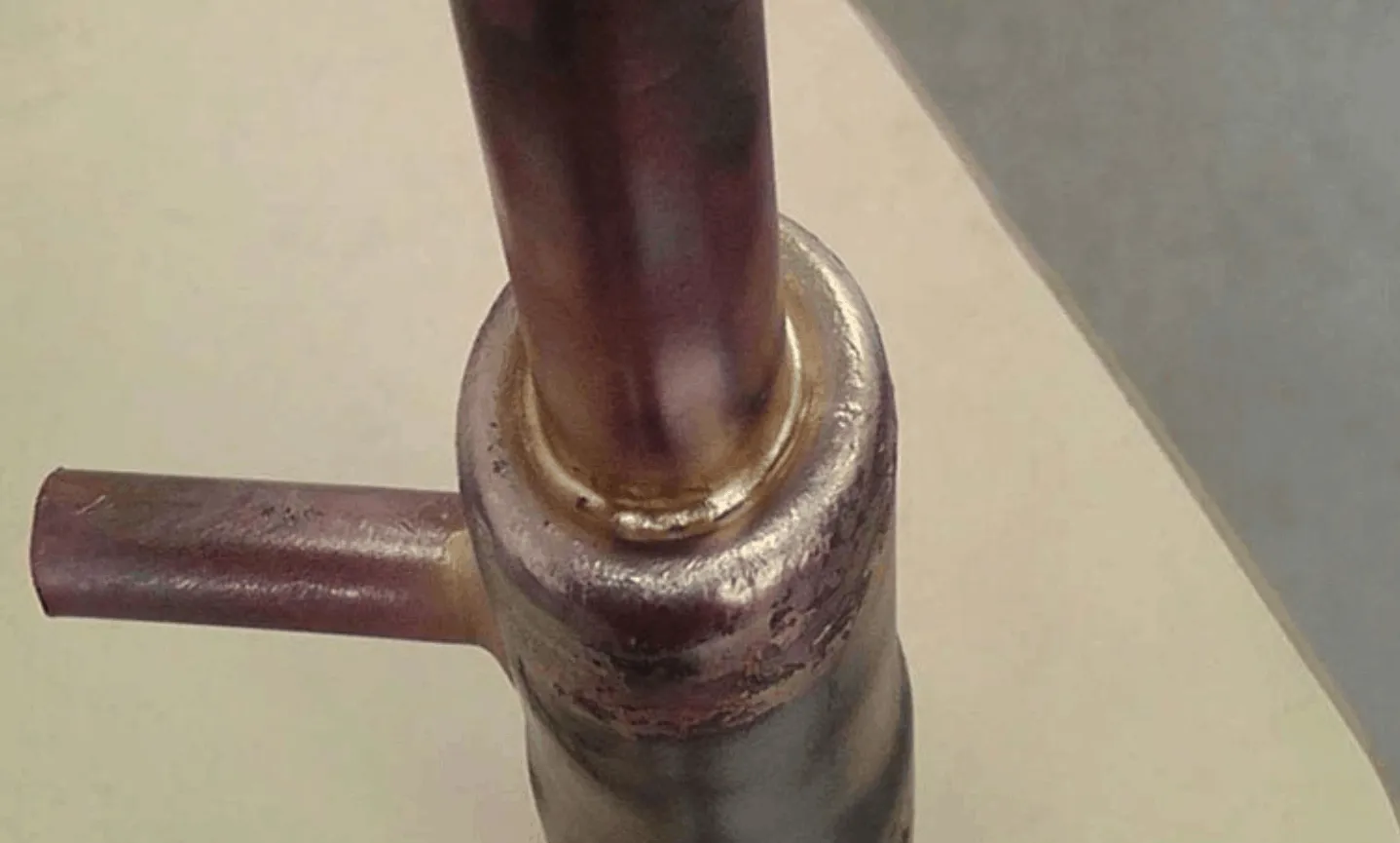
When joint clearance, filler metal, flux, and heating cycle are correct, induction brazing can produce high-strength and leak-tight tube joints suitable for pressure systems and fluid circuits.
8. Lower Rework Rate
Consistent heating and controlled filler flow reduce common defects such as incomplete brazing, overheating, filler starvation, and local oxidation. This improves first-pass yield in tube assembly production.
Common Problems and Solutions
| Problem | Possible Cause | Engineering Solution |
|---|---|---|
| Filler metal does not flow into the joint | Joint temperature too low, clearance too tight or too wide, surface contamination, wrong flux | Increase heating time or power, correct joint clearance, clean surfaces, and select suitable flux/filler. |
| Tube overheats or melts | Excessive power, long heating time, poor temperature control, coil too close | Reduce power, shorten cycle time, adjust coil distance, and use temperature feedback. |
| Joint leaks after brazing | Incomplete filler flow, poor fit-up, insufficient overlap, contamination, voids | Improve joint design, clean parts, use proper filler amount, and verify capillary gap. |
| Uneven heating around tube circumference | Improper coil shape, off-center joint, asymmetric fitting mass | Redesign coil, center the workpiece, rotate the part, or use a multi-turn coil. |
| Oxidation or black surface after brazing | Insufficient flux, overheating, poor atmosphere, dirty surface | Use correct flux, reduce heat exposure, improve cleaning, or add nitrogen protection. |
| Filler forms a ball instead of wetting the joint | Surface oxide, wrong filler, insufficient flux, base metal not at correct temperature | Clean and abrade surface, change filler, apply proper flux, and ensure base metal reaches brazing temperature. |
| Coil overheating | Low cooling water flow, blocked coil, excessive duty cycle, poor coil design | Check water flow, chiller capacity, coil tube size, and cooling circuit cleanliness. |
| Inconsistent joint quality between operators | Manual positioning, inconsistent filler amount, variable heating time | Use fixtures, preform filler rings, timer control, PLC recipes, and operator standard instructions. |
| Cracked joint after cooling | Wrong filler, thermal stress, poor joint design, excessive cooling shock | Select ductile filler, improve joint geometry, reduce thermal gradient, and control cooling rate. |
 Engineering Design Notes

Coil Design Determines Heating Quality
For tube joint manufacturing, coil design is critical. A simple round coil may work for straight tube joints, but elbows, T-joints, distributor blocks, and manifold connections often require special coil shapes. The coil should heat both sides of the joint evenly and allow space for filler feeding, flux application, and operator access.
Joint Clearance Controls Capillary Flow
Brazing depends on capillary action. If the clearance is incorrect, the filler metal will not distribute properly. Tube expansion, fitting tolerance, thermal expansion, and fixture pressure must be considered. The best clearance depends on filler type and material combination, but it must be controlled in production.
Filler Metal Must Match the Application
Copper-to-copper joints often use phosphorus copper filler. Copper-to-brass or copper-to-steel joints often need silver-based filler and proper flux. Stainless steel joints may require silver or nickel-based filler depending on temperature and corrosion requirements. Aluminum tube brazing requires special aluminum filler and tight process control.
Flux Control Is a Quality Issue
Flux improves wetting and prevents oxidation, but excessive flux can create residue, contamination, and post-cleaning problems. Insufficient flux can cause poor filler flow. For high-volume production, automatic flux application or pre-fluxed filler may improve consistency.
Fixture Design Should Be Treated as Part of the Machine
A good induction power supply cannot compensate for poor fixture design. The fixture must hold the tube joint in the correct position, maintain clearance, resist heat, avoid magnetic interference, and allow easy loading and unloading. Ceramic, stainless steel, brass, or non-magnetic materials may be used depending on the heating zone.
Temperature Feedback Is Important for Sensitive Materials
For copper tube brazing, timer-based heating may be enough after process validation. For aluminum, stainless steel, thin-wall tubes, or critical pressure assemblies, temperature feedback is strongly recommended. Infrared sensors or thermal cameras can help reduce overheating and improve repeatability.
Industries Served
Induction brazing systems for tube joint manufacturing serve industries where reliable tube assemblies are important for fluid transport, heat transfer, pressure resistance, or mechanical connection. The system can be adapted from small manual workstations to automatic production cells.
- HVAC equipment manufacturing
- Refrigeration and air conditioning production
- Heat exchanger manufacturing
- Automotive tube and fluid line production
- Hydraulic and pneumatic component manufacturing
- Compressor and condenser manufacturing
- Appliance manufacturing
- Medical and instrument tube assembly production
- Industrial piping component manufacturing
- Energy equipment and process system manufacturing
- Aerospace and precision metal tube assembly manufacturing
- OEM tube joint production lines
Case Study / Typical Application
Application: Induction Brazing Copper Tube to Brass Fitting for HVAC Manufacturing
| Item | Engineering Data |
|---|---|
| Industry | HVAC and refrigeration tube assembly manufacturing |
| Material | Copper tube and brass fitting |
| Tube Size | Outer diameter 12.7 mm – 25.4 mm |
| Joint Type | Tube-to-fitting socket joint |
| Filler Metal | Silver brazing alloy ring or phosphorus copper filler depending on joint requirement |
| Flux | Brazing flux applied to brass fitting area |
| Equipment | 25 kW high-frequency induction brazing system |
| Coil Type | Multi-turn water-cooled copper coil designed around the tube joint |
| Heating Time | Approximately 8–15 seconds per joint, depending on fitting mass |
| Control Mode | Timer-controlled power output with foot switch and optional PLC cycle control |
| Inspection | Visual inspection and pressure leak test |
Process Description
The copper tube and brass fitting were cleaned before assembly. A filler ring was placed at the joint entrance, and flux was applied to the brass area. The tube assembly was placed into a simple positioning fixture to keep the joint centered inside the induction coil. The operator activated the induction brazing system using a foot switch. The coil heated the brass fitting and copper tube at the joint area. When the brazing temperature was reached, the filler metal melted and flowed into the socket clearance.
The heating cycle was optimized so the filler flowed completely around the joint without overheating the tube. After the joint cooled, flux residue was removed and the assembly was inspected. The process produced more consistent results than manual flame brazing because the coil position, heating time, and power setting were repeatable.
Result
The induction brazing system improved tube joint consistency, reduced operator skill dependence, and shortened the heating cycle. The localized heating reduced oxidation and improved the working environment. With fixture-based positioning and filler preforms, the process became suitable for repeated batch production and future semi-automatic integration.
FAQ
1. What is an induction brazing system for tube joint manufacturing?
It is an electromagnetic heating system used to join tube assemblies by melting brazing filler metal at the joint interface. It heats the tube and fitting locally using an induction coil and produces strong, leak-tight tube joints when the process is correctly designed.
2. What tube materials can be brazed by induction?
Common materials include copper, brass, stainless steel, carbon steel, aluminum, and selected nickel alloys. Dissimilar metal joints such as copper-to-brass and copper-to-steel can also be brazed with suitable filler metal and flux.
3. Is induction brazing better than flame brazing?
For production manufacturing, induction brazing is often better because it provides repeatable heating, faster cycle time, no open flame at the joint, easier automation, and lower operator dependence. Flame brazing may still be suitable for low-volume field repair or irregular parts.
4. What power is needed for tube joint brazing?
Small tube joints may need 5–15 kW. Medium copper or brass tube joints commonly use 15–35 kW. Larger stainless steel, carbon steel, or heavy tube assemblies may require 35–80 kW or more. Final selection depends on tube size, material, fitting mass, and required cycle time.
5. What frequency is suitable for tube brazing?
High frequency is commonly used for small and medium tube joints because it provides concentrated heating. Larger or thicker steel parts may require lower frequency for better heating depth. Frequency should be selected together with coil design.
6. Does induction brazing require flux?
Flux depends on material combination and filler metal. Copper-to-copper joints using phosphorus copper filler may not require flux in some cases. Copper-to-brass, copper-to-steel, stainless steel, and many dissimilar joints usually need flux or protective atmosphere to improve wetting.
7. Can induction brazing be automated?
Yes. Induction brazing can be integrated with PLC control, rotary indexing tables, automatic filler feeding, robot handling, pneumatic fixtures, temperature sensors, and leak testing systems. This makes it suitable for high-volume tube manufacturing.
8. Why does the filler metal not flow properly?
Common causes include insufficient temperature, poor cleaning, wrong joint clearance, insufficient flux, wrong filler metal, or uneven heating. The solution is to optimize surface preparation, filler choice, coil design, heating time, and joint fit-up.
9. Can aluminum tubes be brazed by induction?
Yes, but aluminum brazing requires careful control because the brazing temperature is close to the base metal melting temperature. Proper filler, flux or atmosphere, accurate temperature control, and optimized heating cycle are necessary.
10. What information is needed for quotation?
Please provide tube material, tube diameter, wall thickness, fitting material, joint type, filler metal if known, target production rate, required inspection standard, photos or drawings, and available voltage. This information allows engineers to select the correct power supply, coil, fixture, and control method.
Conclusion
An Induction Brazing System for Tube Joint Manufacturing is a practical and efficient solution for producing repeatable, clean, and leak-tight tube joints. By using electromagnetic induction, the system heats only the joint area, melts the filler metal, and allows capillary flow into the joint clearance without melting the base tube. This makes it suitable for HVAC, refrigeration, heat exchanger, automotive, hydraulic, pneumatic, industrial piping, and precision tube assembly production.


The success of an induction brazing process depends on engineering details. Tube material, fitting geometry, joint clearance, filler metal, flux, coil design, heating time, cooling method, and fixture stability all affect the final joint quality. A well-designed induction brazing system reduces operator dependence, improves production repeatability, and supports automation. For manufacturers that need higher throughput, better brazing consistency, and cleaner operation than flame brazing, induction brazing is a strong technical and commercial solution.