
Induction Heating Coils Design
Custom Induction Heating Coil Design for Industrial Applications
Quick Answer: Induction heating coil design is the engineering process of developing a copper inductor that generates a controlled alternating magnetic field around a conductive workpiece. HLQ Induction Equipment Co., Ltd. provides custom induction heating coils for brazing, hardening, annealing, forging, shrink fitting, wire heating, and other industrial processes. Available configurations include helical, pancake, internal, channel, hairpin, split, and specially shaped copper inductors. The optimum coil design depends on workpiece geometry, material properties, operating frequency, heating power, coupling distance, cooling requirements, and production cycle time.
Engineering Selection: An induction coil must be matched to the power supply and the workpiece. Coil geometry alone cannot determine heating performance. The correct design requires evaluation of electromagnetic coupling, current distribution, heat transfer, electrical matching, mechanical clearance, and cooling capacity. Final performance should be verified using representative production samples.
Table of Contents
-
- What Is Induction Heating Coil Design?
- Types of Induction Heating Coils
- Key Applications
- Suitable Materials
- Working Principle
- Technical Specifications
- Recommended Coil Selection
- Coil Geometry and Coupling Distance
- Frequency Selection and Skin Depth
- Engineering Calculations
- Coil Design and Manufacturing Workflow
- Coil Cooling and Construction
- Control System and Automation
- Engineering Application Example
- Common Problems and Solutions
- Engineering Selection Guide
- Advantages and Limitations
- Why Choose HLQ Induction Equipment?
- Core FAQs
What Is Induction Heating Coil Design?
An induction heating coil is a conductive inductor, normally manufactured from copper tubing, copper plate, or specially formed copper conductors, that produces a changing magnetic field when alternating electrical current flows through it.
The changing magnetic field induces electrical currents within a conductive workpiece. Electrical resistance converts the induced current into heat, allowing selected regions of a metal component to be heated without direct contact with a conventional heating element.
The induction coil is one of the most important components of the entire induction heating system because it influences:
- Electromagnetic coupling between the power supply and workpiece.
- Distribution of induced electrical current.
- Location and uniformity of the heated region.
- Required generator current, frequency, and matching arrangement.
- Heating cycle time and useful energy transfer.
- Mechanical clearance and production repeatability.
- Cooling requirements and coil operating life.
For industrial applications, custom induction coils are normally designed according to the actual material, workpiece dimensions, process temperature, and production requirements.
| Design Parameter | Engineering Requirement | Influence on Heating Performance |
|---|---|---|
| Coil Geometry | Match the workpiece and heating zone | Determines magnetic field distribution |
| Operating Frequency | Match material, geometry, and heating requirements | Influences electrical penetration depth |
| Coil-to-Workpiece Gap | Maintain safe and repeatable clearance | Affects electromagnetic coupling |
| Number of Turns | Match inductance and power supply requirements | Influences load matching and field distribution |
| Copper Conductor | Select suitable dimensions and construction | Influences current carrying capability and thermal behavior |
| Cooling System | Provide adequate coolant flow and heat removal | Protects copper conductors and electrical connections |
| Workpiece Positioning | Maintain consistent alignment | Improves heating repeatability |
| Process Validation | Test representative workpieces | Confirms actual heating results |
Types of Induction Heating Coils
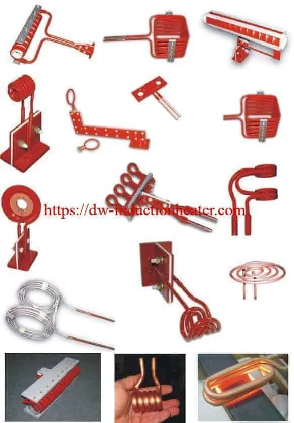
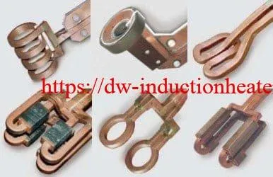
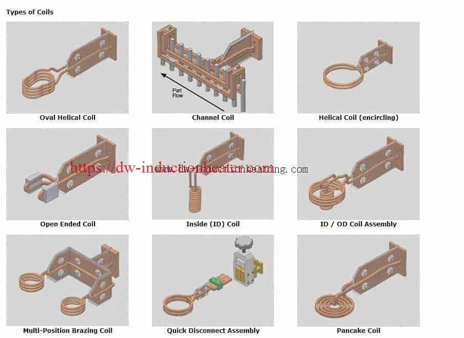
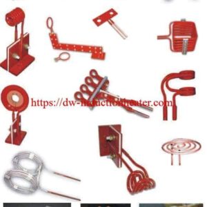
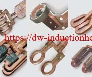
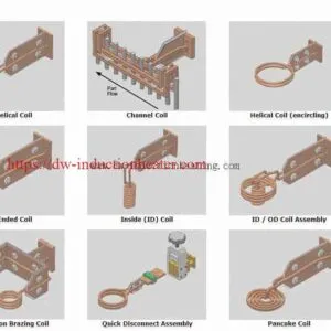
Different induction heating processes require different coil shapes. Common configurations include helical, pancake, internal, channel, hairpin, split, and specially formed inductors.
1. Helical Induction Coils
A helical induction coil consists of one or more turns arranged around a cylindrical or approximately cylindrical heating zone. It is commonly used for rods, shafts, tubes, bars, bearings, and similar components.
Helical coils can provide effective circumferential heating when the workpiece is correctly centered. Heating uniformity depends on coil length, turn pitch, end effects, part geometry, and workpiece movement.
2. Pancake Induction Coils
Pancake coils use a flat spiral or related planar conductor arrangement. They are commonly used for heating metal plates, discs, flat surfaces, and selected local regions of large components.
The coil-to-surface distance must be controlled carefully because changes in clearance can affect heating intensity and temperature distribution.
3. Internal Diameter Induction Coils
Internal induction coils are designed to heat the inside surface of a hollow component. Typical applications include bearing bores, cylinders, sleeves, rings, and internal hardening operations.
These coils require careful attention to limited space, cooling passages, electrical insulation, and mechanical alignment.
4. Hairpin and U-Shaped Coils
Hairpin coils are useful when the required heating zone is accessible from one side or when a complete encircling coil is unsuitable.
They may be used for localized heating, selected hardening applications, seam heating, and elongated surface regions.
5. Channel and Tunnel Coils
Channel coils are designed for continuous or semi-continuous processing. Workpieces move through a defined magnetic field during heating.
Applications may include wires, strips, bars, and conveyor-fed components.
6. Split and Open-Ended Coils
Split or open-ended coils provide access to parts that cannot easily be inserted into a conventional enclosed inductor.
These designs require careful analysis of magnetic field symmetry, mechanical connections, and electrical matching.
7. Custom-Profile Induction Coils
Custom-profile coils are manufactured to match complex workpiece shapes or localized heating requirements. They may incorporate formed copper conductors, dedicated fixtures, insulation, and magnetic flux concentrators.
| Coil Type | Typical Workpiece | Application | Main Design Consideration |
|---|---|---|---|
| Helical Coil | Rod, shaft, tube | Forging, brazing, hardening | Axial and circumferential uniformity |
| Pancake Coil | Plate, disc | Surface and localized heating | Surface coupling and edge effects |
| Internal Coil | Bore, cylinder, ring | Internal hardening and heating | Clearance and cooling |
| Hairpin Coil | Long or accessible surface | Selective heating and hardening | Field symmetry and return path |
| Channel Coil | Wire, strip, moving components | Continuous heating and annealing | Line speed and heating uniformity |
| Split Coil | Large or irregular component | Special heating applications | Mechanical access and load matching |
| Custom-Profile Coil | Complex industrial component | Specialized heat treatment | Field concentration and repeatability |
Key Applications
Custom induction heating coils are used in many industrial processes. The required design depends on whether the objective is joining, surface hardening, through-heating, annealing, melting, or controlled thermal expansion.
| Application | Typical Material | Recommended Coil Concept | Process Objective |
|---|---|---|---|
| Induction Brazing | Copper, brass, steel, stainless steel | Helical or custom formed coil | Heat the joint to brazing temperature |
| Induction Hardening | Carbon steel and suitable alloy steel | Encircling, scanning, or profile coil | Controlled surface austenitizing before quenching |
| Induction Forging | Carbon steel, alloy steel, copper alloys | Multi-turn helical coil | Heat the required billet or forging section |
| Induction Annealing | Copper, steel, stainless steel | Helical, tunnel, or channel coil | Provide the required thermal cycle |
| Induction Shrink Fitting | Steel rings, gears, sleeves | Helical or profile coil | Produce controlled thermal expansion |
| Induction Melting | Steel, copper, aluminum, precious metals | Furnace-specific coil | Deliver heat to the charge and/or conductive crucible |
| Surface Preheating | Steel plate, pipe, structural components | Pancake or specialized surface coil | Heat a selected region before processing |
| Continuous Wire Heating | Steel, copper, nickel alloys | Channel or helical coil | Heat continuously moving material |
For copper and brass joining applications, explore HLQ’s custom induction brazing coils and their application-specific heating arrangements.
For shafts, gears, and other surface-hardened components, refer to the induction hardening coil design product guide.
Suitable Materials
Induction heating is suitable for many electrically conductive materials. However, the electromagnetic behavior of each material can differ significantly.
Electrical resistivity, magnetic permeability, thermal conductivity, specific heat, and temperature-dependent material properties influence the final heating performance.
| Material | Electrical and Magnetic Characteristics | Coil Design Consideration |
|---|---|---|
| Carbon Steel | Electrical conductivity and temperature-dependent magnetic permeability | Account for the Curie transition and required heating depth |
| Stainless Steel | Properties depend on stainless steel grade | Match frequency and power to the actual alloy |
| Copper | High electrical and thermal conductivity | Optimize coupling, power delivery, and heat transfer |
| Brass | Conductive copper-based alloy | Account for alloy composition and process temperature |
| Aluminum | Nonferromagnetic and highly conductive | Consider charge geometry and electromagnetic coupling |
| Titanium | Lower thermal conductivity than copper or aluminum | Control localized heating and surface condition |
| Nickel Alloys | Temperature-dependent electrical and magnetic properties | Verify frequency selection and thermal response |
Working Principle
The operating principle of an induction heating coil is based on electromagnetic induction.
When alternating current flows through the copper conductor, it generates a changing magnetic field. This field induces electrical currents in a conductive workpiece positioned within the effective magnetic field.
The resulting electrical losses generate heat in the workpiece.
In suitable ferromagnetic materials and temperature ranges, magnetic hysteresis may also contribute to heating. The relative importance of this effect depends on the material and operating conditions.
| Step | Component | Function |
|---|---|---|
| 1 | Electrical Power Supply | Provides electrical input energy |
| 2 | Induction Heating Inverter | Generates alternating current at the required operating frequency |
| 3 | Matching Circuit | Matches the electrical load to the inverter |
| 4 | Induction Coil | Produces the changing magnetic field |
| 5 | Conductive Workpiece | Absorbs electromagnetic energy and generates heat |
| 6 | Process Control | Regulates power, time, and applicable feedback variables |
| 7 | Cooling System | Removes waste heat from the coil and other designated components |
Why Coil Geometry Matters
The magnetic field is not distributed identically around every coil shape.
For example, a helical coil can concentrate its useful field inside the enclosed region, while a pancake coil produces a different magnetic field distribution suitable for selected surface-heating applications.
Asymmetrical workpiece positioning, irregular coil shapes, or an unsuitable connection arrangement may create nonuniform heating.
The final magnetic field distribution should therefore be evaluated together with the workpiece and its operating position.
Technical Specifications
HLQ manufactures induction heating coils in different configurations according to customer requirements. Because the coil is a customized component, the finished specifications depend on the workpiece, application, power supply, and cooling arrangement.
The following table distinguishes published product capabilities from parameters that must be determined during engineering design.
| Parameter | Specification | Notes |
|---|---|---|
| Product | Custom Induction Heating Coil | Application-specific copper inductor |
| Manufacturer | HLQ Induction Equipment Co., Ltd. | China |
| Coil Types | Helical, pancake, internal, channel, hairpin, split, and custom profiles | Published product families |
| Conductor Material | Copper tubing, copper plate, or formed copper conductors | Selected according to electrical and mechanical requirements |
| Number of Turns | Single-turn or multi-turn | Project-specific |
| Coil Dimensions | Custom design | Based on workpiece drawings and operating clearance |
| Coil Inner Diameter | Application-dependent | Confirm finished dimensions in engineering drawing |
| Operating Frequency | Matched to the power supply and workpiece | No universal frequency specification |
| Heating Power | Matched to the generator and load | Not a standalone coil power rating |
| Cooling Method | Typically water-cooled for industrial high-current designs | Confirm individual coil configuration |
| Cooling Water Flow | Determined by thermal and hydraulic design | Must be specified for the selected coil |
| Cooling Water Pressure | Project-specific | Confirm allowable range and pressure drop |
| Coil Insulation | Application-specific insulation and supports | Must meet electrical and thermal requirements |
| Electrical Connections | Custom terminals or matching connections | Confirm compatibility with power supply |
| Manufacturing Drawings | Available according to project scope | Dimensions and tolerances must be approved |
| Application Testing | Subject to project requirements | Agree acceptance conditions before manufacturing |
Recommended Coil Selection
The appropriate induction coil should be selected according to the workpiece shape and the required heating process rather than from a universal model list.
The frequency categories below are preliminary engineering guidance only. Exact numerical frequency, rated power, and coil design must be confirmed for the specific application.
| Application | Material | Recommended Coil | Frequency Consideration |
|---|---|---|---|
| Copper Tube Brazing | Copper and brass | Short helical or custom-profile coil | Usually high-frequency screening; confirm by joint geometry |
| Steel Shaft Hardening | Carbon or alloy steel | Encircling or scanning coil | Match to required surface case and heating time |
| Large Steel Bar Heating | Carbon steel | Multi-turn helical coil | Consider medium-frequency heating for suitable larger sections |
| Internal Bore Hardening | Suitable steel | Internal diameter coil | Match to bore diameter and case-depth requirements |
| Flat Plate Heating | Steel or conductive alloys | Pancake or specialized surface coil | Match to heating zone and material thickness |
| Continuous Wire Annealing | Copper, steel, nickel alloys | Channel or helical coil | Match to wire diameter and line speed |
| Gear Shrink Fitting | Steel gears and rings | Helical or custom-profile coil | Match to expansion temperature and component geometry |
| Metal Melting | Steel, copper, aluminum | Dedicated furnace coil | Match to charge, crucible, and melting power supply |
Coil Geometry and Coupling Distance
The distance between the induction coil and workpiece is an important factor affecting electromagnetic coupling.
In many induction heating applications, reducing the coil-to-workpiece gap can improve coupling. However, the minimum practical clearance must also account for thermal expansion, workpiece movement, fixture tolerances, insulation, and operating safety.
1. Coil-to-Workpiece Gap
The coil should be positioned as close as safely and repeatably practical to the required heating zone.
A gap that is too large may reduce useful power transfer. A gap that is too small may create collision, short-circuit, insulation, or thermal damage risks.
2. Number of Coil Turns
The number of coil turns influences inductance, field distribution, load impedance, and electrical matching.
A larger number of turns does not automatically produce better heating. The final design must remain compatible with the inverter, matching transformer, capacitor network, and required heating cycle.
3. Coil Active Length
The active length determines how much of the workpiece is exposed to the intended magnetic field distribution.
A coil that is too short may produce excessive axial temperature gradients. A coil that is unnecessarily long may heat material outside the required process zone.
4. Coil Centering
For cylindrical components, inaccurate positioning can create different gaps around the circumference.
This may lead to uneven heating, especially when the process is sensitive to small variations in electromagnetic coupling.
Suitable fixtures, rotation, or scanning movement can improve repeatability when required.
| Parameter | Potential Problem | Engineering Solution |
|---|---|---|
| Excessive Coil Gap | Reduced electromagnetic coupling | Review coil dimensions and fixture arrangement |
| Insufficient Clearance | Collision or electrical fault risk | Account for workpiece expansion and tolerances |
| Incorrect Turn Spacing | Uneven heating or matching problems | Optimize conductor spacing and magnetic field distribution |
| Off-Center Workpiece | Asymmetrical heating | Improve centering and positioning repeatability |
| Improper Active Length | Incorrect heating-zone coverage | Match the coil to the required heated area |
| Uncontrolled Lead Geometry | Unwanted magnetic field and electrical effects | Review coil connections and return-current paths |
Frequency Selection and Skin Depth
Operating frequency influences the distribution of induced electrical currents within the workpiece.
Under simplified electromagnetic conditions, higher frequencies produce a smaller reference electrical penetration depth, while lower frequencies produce a larger reference penetration depth.
This relationship is described by the skin-effect equation.
Skin Depth Formula
δ = √[ρ / (π × f × μ)]
Where:
- δ = Reference electrical skin depth, in meters.
- ρ = Electrical resistivity, in Ω·m.
- f = Operating frequency, in Hz.
- μ = Absolute magnetic permeability, in H/m.
For a material with relative permeability μr, the absolute permeability is μ = μ0 × μr, where μ0 is the permeability of free space.
This equation describes the reference current penetration depth under the assumed electrical and magnetic conditions.
Important: The calculated skin depth is not the same as the final temperature penetration depth. Actual heating depth also depends on heat conduction, heating time, temperature-dependent properties, and the geometry of the workpiece.
Example: Copper Skin Depth
The following values are theoretical estimates for copper at approximately 20°C, using an electrical resistivity of 1.72 × 10⁻⁸ Ω·m and relative magnetic permeability close to 1.
| Frequency | Approximate Skin Depth | Engineering Interpretation |
|---|---|---|
| 10 kHz | 0.66 mm | Relatively deeper electrical current distribution |
| 30 kHz | 0.38 mm | Reduced electrical penetration depth |
| 50 kHz | 0.30 mm | Higher surface current concentration |
| 100 kHz | 0.21 mm | Shallower electrical current penetration |
| 200 kHz | 0.15 mm | Strong surface-current concentration under reference conditions |
These values are reference calculations, not recommendations for a particular copper brazing, melting, or annealing operation.
For a more detailed explanation, see HLQ’s skin effect and induction heating depth calculation guide.
Frequency Selection for Steel
Steel requires additional attention because its electrical resistivity and magnetic permeability change with temperature.
For ferromagnetic steel, magnetic permeability can decrease substantially as the material approaches and passes through the Curie transition.
Therefore, a frequency selected only from room-temperature material properties may not predict the final heating behavior accurately.
Surface-hardening applications also require consideration of thermal conduction, austenitizing temperature, quenching, and the specified hardened case depth.
Engineering Calculations
Before manufacturing a new induction coil, engineers should estimate the thermal energy required for the workpiece.
The result provides an initial indication of the necessary heating power but does not determine the coil’s final dimensions or electrical matching.
1. Theoretical Heating Energy
For sensible heating without a phase transition:
Q = m × Cp × ΔT
Where:
- Q = Required thermal energy, kJ.
- m = Effective heated mass, kg.
- Cp = Approximate mean specific heat capacity, kJ/kg·K.
- ΔT = Required temperature increase, K.
2. Example: Heating a Steel Component
Consider an illustrative steel component with an effective heated mass of 0.5 kg.
The required temperature rises from 25°C to 750°C within 20 seconds.
For this preliminary calculation, assume an average specific heat capacity of 0.60 kJ/kg·K.
| Parameter | Value | Notes |
|---|---|---|
| Material | Steel | Illustrative application |
| Effective Heated Mass | 0.5 kg | Assumed |
| Initial Temperature | 25°C | Assumed |
| Target Temperature | 750°C | Assumed |
| Temperature Increase | 725 K | Calculated |
| Mean Specific Heat | 0.60 kJ/kg·K | Approximate assumption |
| Required Heating Time | 20 seconds | Assumed |
| Theoretical Thermal Energy | 217.5 kJ | Calculated |
| Equivalent Thermal Energy | 0.0604 kWh | Calculated |
| Average Useful Thermal Power | 10.9 kW | Calculated before losses |
The theoretical useful thermal power is approximately 10.9 kW.
For illustration only, if overall electrical-to-workpiece heating efficiency were assumed to be 45%, the estimated average electrical input would be approximately 24.2 kW.
This result is not a guaranteed equipment rating or a completed factory test. Final design requires evaluation of coil coupling, electrical losses, heat transfer, workpiece properties, and the actual production conditions.
3. Why Heating Power Alone Is Not Enough
Two induction coils connected to generators of similar rated power may produce different results because the electromagnetic load conditions are different.
A complete design must consider the effective workpiece resistance, coil inductance, resonant matching, coupling efficiency, current distribution, and acceptable temperature profile.
| Parameter | Influence | Required Verification |
|---|---|---|
| Rated Generator Power | Available electrical power | Input/output rating and loaded operation |
| Operating Frequency | Electrical penetration depth and matching | Loaded operating range |
| Coil Inductance | Electrical resonance and load matching | Coil and matching-circuit compatibility |
| Coupling Distance | Useful electromagnetic energy transfer | Operating clearance and heating test |
| Workpiece Material | Electrical and thermal response | Verified material grade |
| Heating Time | Thermal conduction and final temperature profile | Measured production cycle |
| Cooling Capacity | Inductor operating reliability | Flow, pressure, and temperature checks |
Coil Design and Manufacturing Workflow
A reliable custom induction heating coil normally requires engineering review, manufacturing preparation, and application validation.
| Step | Engineering Process | Required Output |
|---|---|---|
| 1 | Workpiece Analysis | Material, dimensions, and required heating zone |
| 2 | Heating Requirement Review | Target temperature, cycle time, and quality requirements |
| 3 | Power Supply Matching | Available power and operating frequency range |
| 4 | Coil Geometry Development | Proposed turns, dimensions, and conductor configuration |
| 5 | Mechanical Design | Mounting, insulation, and clearance requirements |
| 6 | Cooling Circuit Design | Water passages, flow requirements, and connections |
| 7 | Coil Manufacturing | Completed copper inductor assembly |
| 8 | Inspection and Testing | Dimensional, electrical, and cooling checks |
| 9 | Heating Application Trial | Recorded heating temperature and cycle performance |
| 10 | Final Approval | Accepted design and production documentation |
Coil Cooling and Construction
Industrial induction heating coils often carry high alternating current and operate close to hot workpieces. Effective cooling is therefore essential for many applications.
Water-cooled copper tubing is commonly used because copper provides high electrical conductivity and suitable thermal performance.
Copper Conductor Selection
The conductor dimensions should be selected according to electrical current, operating frequency, mechanical strength, cooling requirements, and the available installation space.
The use of thick copper or a larger copper tube does not automatically result in a better coil. Current distribution, especially at higher frequencies, can reduce the effective conducting area.
Cooling Water Design
The cooling system should provide adequate flow through the complete coil assembly, including bends, connections, and any sections with restricted passages.
Cooling design should account for water quality, operating pressure, inlet temperature, expected heat rejection, and required protection functions.
| Component | Engineering Requirement | Inspection Method |
|---|---|---|
| Copper Tubing | Suitable electrical and mechanical dimensions | Dimensional inspection |
| Water Passages | Adequate flow through the complete circuit | Flow verification |
| Copper Connections | Reliable mechanical and electrical joints | Visual and electrical inspection |
| Cooling Circuit Integrity | No unacceptable leakage | Approved leak or pressure test |
| Turn Insulation | Appropriate electrical and thermal insulation | Inspection according to equipment requirements |
| Coil Supports | Stable positioning during heating | Mechanical inspection |
| Cooling Interlocks | Prevent unsafe operation under inadequate cooling conditions | Functional protection test |
Control System and Automation
The induction coil is a passive electromagnetic component. Process control is normally provided by the induction heating power supply and associated temperature, movement, and automation systems.
Depending on the application, the complete system may include:
- Adjustable induction heating power.
- Heating cycle timers.
- Temperature sensors.
- PID temperature regulation.
- Workpiece rotation or scanning movement.
- PLC and HMI control.
- Cooling-water monitoring.
- Electrical fault protection.
- Process data recording.
The exact availability of these functions depends on the selected induction heating machine and control configuration.
| Function | Purpose | Verification Requirement |
|---|---|---|
| Power Regulation | Controls delivered heating power | Verify response with the actual coil and load |
| Heating Timer | Defines process duration | Confirm cycle repeatability |
| Temperature Monitoring | Measures selected process temperature | Confirm sensor type, position, and calibration |
| Workpiece Movement | Improves heating distribution where required | Check speed and positioning |
| Cooling Protection | Protects coil and power supply | Verify fault response |
| PLC Automation | Coordinates production operations | Confirm I/O and control sequence |
| Process Data Recording | Supports quality verification | Define recorded variables and sampling method |
Engineering Application Example
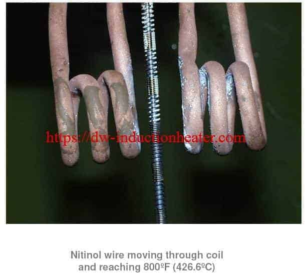
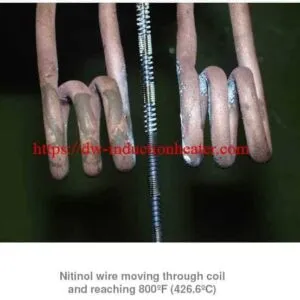
Continuous Induction Heating of Nitinol Wire
Continuous wire heating is one application where the coil geometry, heating-zone length, and movement speed must be considered together.
The original HLQ product gallery includes an image of Nitinol wire passing through an induction heating coil. The image identifies a wire temperature of approximately 800°F (426.7°C).
For this type of application, the following parameters should be determined before final coil selection.
| Parameter | Engineering Requirement |
|---|---|
| Wire Material | Verify actual alloy composition and properties |
| Wire Diameter | Specify the processing diameter range |
| Line Speed | Define required continuous production speed |
| Heating Temperature | Specify the required process temperature |
| Heating Zone | Define effective coil heating length |
| Coil Alignment | Maintain repeatable wire positioning |
| Electrical Power | Calculate from material, line speed, and required temperature |
| Frequency | Match to wire diameter and material behavior |
| Temperature Measurement | Use an appropriate validated measurement method |
Application Note: The original image provides an application illustration, not a complete test report. It does not establish the coil power, operating frequency, wire diameter, line speed, or production energy consumption. These values must be confirmed separately before the image is used as evidence of guaranteed performance.
Common Problems and Solutions
| Problem | Possible Cause | Recommended Solution |
|---|---|---|
| Slow Heating | Incorrect matching, excessive gap, or insufficient useful power | Verify power supply operation, coupling, and load conditions |
| Uneven Heating | Incorrect coil geometry or workpiece positioning | Review coil design and fixture alignment |
| Local Overheating | Magnetic field concentration or unsuitable heating cycle | Modify coil geometry or process parameters |
| Excessive Coil Temperature | Insufficient water flow or excessive electrical losses | Stop heating and inspect cooling and current conditions |
| Coil Leakage | Damaged copper tubing, failed joints, or mechanical wear | Remove the coil from service and inspect the damaged section |
| Electrical Arcing | Insulation damage or insufficient electrical clearance | De-energize and conduct qualified electrical inspection |
| Unstable Generator Operation | Load mismatch or electrical connection problems | Inspect the resonant circuit and verify coil compatibility |
| Premature Coil Failure | Cooling problems, vibration, collision, or excessive current | Review mechanical supports, cooling, and operating limits |
| Inconsistent Product Quality | Variable workpiece position or process conditions | Improve fixture repeatability and validate the heating recipe |
Engineering Selection Guide
Designing an industrial induction heating coil requires a systematic evaluation of the workpiece and heating process.
Step 1: Identify the Workpiece
Provide the material grade, dimensions, shape, weight, and specific region that requires heating.
Step 2: Define the Required Heating Result
Specify the starting temperature, target temperature, allowable temperature distribution, heating time, and production cycle.
Step 3: Confirm the Power Supply
Identify the available induction heating power supply, rated output power, operating frequency range, matching arrangement, and electrical connection dimensions.
Step 4: Select the Initial Coil Type
Choose a suitable helical, pancake, internal, channel, scanning, or custom-profile arrangement based on the workpiece and required heating zone.
Step 5: Determine Electrical Matching
Evaluate the expected coil inductance, load impedance, operating frequency, and required current.
Step 6: Review Mechanical Clearances
Check workpiece movement, thermal expansion, coil-to-part gap, mounting requirements, and access for loading and unloading.
Step 7: Design the Cooling Circuit
Specify water flow, pressure drop, inlet temperature, cooling capacity, and protective monitoring.
Step 8: Manufacture and Inspect
Manufacture the coil according to approved drawings and inspect its dimensions, electrical connections, mechanical supports, insulation, and cooling circuit.
Step 9: Conduct an Application Trial
Where required, use representative workpieces to verify the heating pattern, cycle time, process quality, and operating stability.
Step 10: Approve the Final Design
Confirm that the completed coil meets the agreed engineering specifications and application acceptance criteria.
| Required Information | Customer Data |
|---|---|
| Application | Heating, brazing, hardening, annealing, forging, or other process |
| Material | Material grade and composition |
| Workpiece Dimensions | Drawing with dimensions and tolerances |
| Heating Zone | Required heated length, area, or depth |
| Initial Temperature | Starting temperature in °C |
| Target Temperature | Required temperature in °C |
| Heating Time | Seconds or minutes per cycle |
| Production Rate | Pieces/hour, kg/hour, or line speed |
| Existing Induction Generator | Manufacturer and model |
| Rated Power | kW |
| Frequency Range | kHz |
| Cooling Conditions | Water flow, pressure, temperature, and quality |
| Workpiece Movement | Stationary, rotating, scanning, or continuous |
| Quality Requirements | Temperature, hardness, joint quality, or other acceptance criteria |
For additional design considerations, read HLQ’s induction heating coils design technical guide.
Advantages and Limitations
Advantages of Custom Induction Heating Coils
| Advantage | Engineering Benefit |
|---|---|
| Application-Specific Geometry | Supports heating of different workpiece shapes and dimensions |
| Localized Heating | Allows the magnetic field to be directed toward selected regions |
| Improved Process Repeatability | Supports consistent heating when positioning and power are controlled |
| Power Supply Matching | Allows the inductor to be designed for the actual electrical system |
| Automation Compatibility | Supports integration into suitable automated heating stations |
| Adaptable Construction | Allows customized connections, fixtures, and cooling arrangements |
Limitations of Induction Coil Design
| Limitation | Engineering Consideration |
|---|---|
| Workpiece-Specific Design | A coil optimized for one part may not be suitable for another part |
| Electrical Matching Requirements | The coil must remain compatible with the complete resonant heating system |
| Cooling Dependency | High-current coils may require reliable water cooling |
| Mechanical Clearance | Workpiece movement and thermal expansion must be considered |
| Heating Uniformity | Complex parts may require special coil shapes or movement |
| Manufacturing Complexity | Irregular coils may require specialized fabrication and inspection |
| Process Validation | Critical applications may require thermal and quality testing |
Why Choose HLQ Induction Equipment?
HLQ Induction Equipment Co., Ltd. provides industrial induction heating equipment and customized induction coil solutions for various metalworking applications.
Custom coil selection should be based on the complete heating process rather than coil appearance alone.
Custom Coil Design
HLQ can evaluate workpiece drawings and application requirements to develop suitable copper inductor configurations.
Induction Power Supply Matching
Coil selection can be reviewed together with the required induction power, operating frequency, and generator interface.
Industrial Application Support
Custom coils can be considered for brazing, hardening, forging, annealing, shrink fitting, and other localized heating processes.
Manufacturing and Inspection
Depending on the project scope, design documentation, dimensional inspection, cooling-circuit verification, and application testing can be discussed before order confirmation.
Complete Heating System Integration
For new production systems, coil engineering can be coordinated with the power supply, workpiece fixture, cooling system, temperature measurement, and control equipment.
For further engineering information, refer to HLQ’s induction heating coil design guide for engineers.
Core FAQs
1. What is an induction heating coil?
An induction heating coil is an electrical conductor, normally made from copper, that generates an alternating magnetic field when connected to a suitable induction power supply. The field induces electrical currents within a conductive workpiece, producing heat.
2. What materials are induction heating coils made from?
Industrial induction coils are commonly manufactured from copper tubing, copper plate, or specially formed copper conductors. The final material and construction depend on electrical current, frequency, cooling, and mechanical requirements.
3. What are the main types of induction heating coils?
Common types include helical, pancake, internal, channel, hairpin, split, and custom-profile coils. Different shapes are selected for different workpiece geometries and heating objectives.
4. How do I select the correct induction coil?
Coil selection depends on the workpiece material, dimensions, target heating zone, temperature, cycle time, generator power, operating frequency, and required production rate. Final design may require application testing.
5. How many turns should an induction heating coil have?
The required number of turns depends on coil geometry, inductance, electrical matching, magnetic field distribution, and the workpiece. There is no universal number of turns suitable for all induction heating applications.
6. What is the ideal distance between the coil and workpiece?
The ideal coupling distance depends on the coil shape, material, temperature, mechanical tolerances, and process requirements. Smaller clearances may improve coupling, but the design must provide sufficient insulation and mechanical clearance.
7. How does induction heating frequency affect coil design?
Frequency affects the electrical current distribution in the workpiece and coil. Higher frequencies generally produce smaller reference skin depths when material properties are unchanged. Final heating depth also depends on time and thermal conduction.
8. Can the same induction coil be used for different workpieces?
Sometimes. A coil may accommodate several workpieces with similar dimensions and heating requirements. However, precision processes often require dedicated coils to maintain heating uniformity and repeatability.
9. Why are industrial induction coils water-cooled?
Many industrial coils carry high alternating currents and operate near hot workpieces. Water cooling helps remove heat from the copper conductor and maintain acceptable operating temperatures.
10. Why does an induction coil produce uneven heating?
Possible causes include unsuitable coil geometry, inconsistent coupling gaps, incorrect workpiece positioning, magnetic field concentration, and inappropriate heating parameters. Engineering analysis and representative testing are required to identify the cause.
11. How long does an induction heating coil last?
Coil life depends on current loading, cooling-water quality, operating temperature, mechanical handling, vibration, insulation, and maintenance. A universal service-life guarantee cannot be established without defined operating conditions.
12. Can HLQ manufacture a custom induction heating coil?
HLQ provides custom induction heating coil solutions for various industrial applications. Customers should submit their workpiece drawings, material specifications, heating requirements, and induction generator information for engineering review and quotation.
Request a Custom Induction Heating Coil Quotation
Looking for a customized induction heating coil for your industrial application?
HLQ Induction Equipment Co., Ltd. can review your workpiece requirements and propose a suitable induction coil configuration.
Please provide the following information:
| Required Information | Customer Specification |
|---|---|
| Application | Specify the heating process |
| Material | Material grade |
| Workpiece Drawing | 2D drawing, 3D model, or detailed dimensions |
| Workpiece Weight | kg |
| Heating Area | Required length, diameter, or local heating zone |
| Initial Temperature | °C |
| Target Temperature | °C |
| Heating Time | Seconds or minutes |
| Production Rate | Pieces/hour or kg/hour |
| Induction Power Supply | Manufacturer and model |
| Rated Power | kW |
| Operating Frequency | kHz |
| Cooling System | Available cooling-water conditions |
| Installation Country | Country and applicable electrical supply |
Manufacturer: HLQ Induction Equipment Co., Ltd.
Email: sales@dw-inductionheater.com
Tel / WhatsApp: +86-13155965571
Website: dw-inductionheater.com
Technical References and Engineering Review
The following original HLQ technical resources are retained for additional engineering reference:
- Induction Heating Coil Design and Basic Design — Technical PDF
- Induction Heating Coils Design — Technical Reference PDF
| Item | Details |
|---|---|
| Manufacturer | HLQ Induction Equipment Co., Ltd. |
| Product Category | Custom Induction Heating Coils |
| Primary Application | Industrial Induction Heating |
| Engineering Parameters | Application-specific |
| Design Data | Manufacturer product information and engineering calculations |
| Calculation Examples | Illustrative estimates, not verified production test results |
| Last Content Review | October 2026 |
Engineering Disclaimer: Custom induction coil performance depends on the complete heating system, workpiece properties, operating frequency, power delivery, cooling, and production conditions. The theoretical calculations and application examples presented here are intended for preliminary engineering guidance. Final dimensions, frequency, current, heating results, and cooling requirements must be verified for the specific project.
Induction Heating Coil Design and Basic Design
induction heating coils design
HLQ-induction-coil-design-brochure
HLQ_Induction_Heating_Coil_Design_Engineering_Brochure
Related products
-

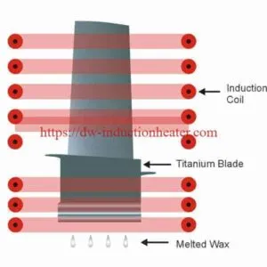
Induction Heating Titanium Blade
-
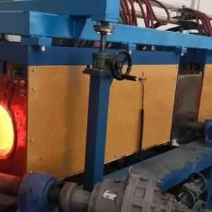
Steel Billet Heating Furnace with Induction For forging rolling mills and extrusion bars-billets-rods
-
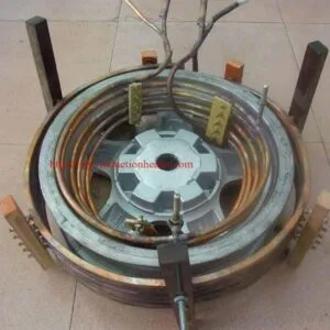
Induction Heating Aluminum Automotive Wheel Hub
-
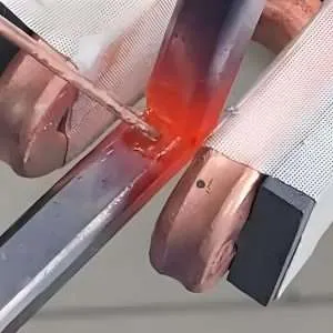
Portable Induction Brazing Machine for Copper, Brass, Steel and HVAC Tube Joints
-

Pipe-Tube Heating Systems With Induction